
Anchorage Performance of an Innovative Assembled Joint with Large-Diameter Steel Bar Grout Lapping in Concrete Reserved Hole

Abstract
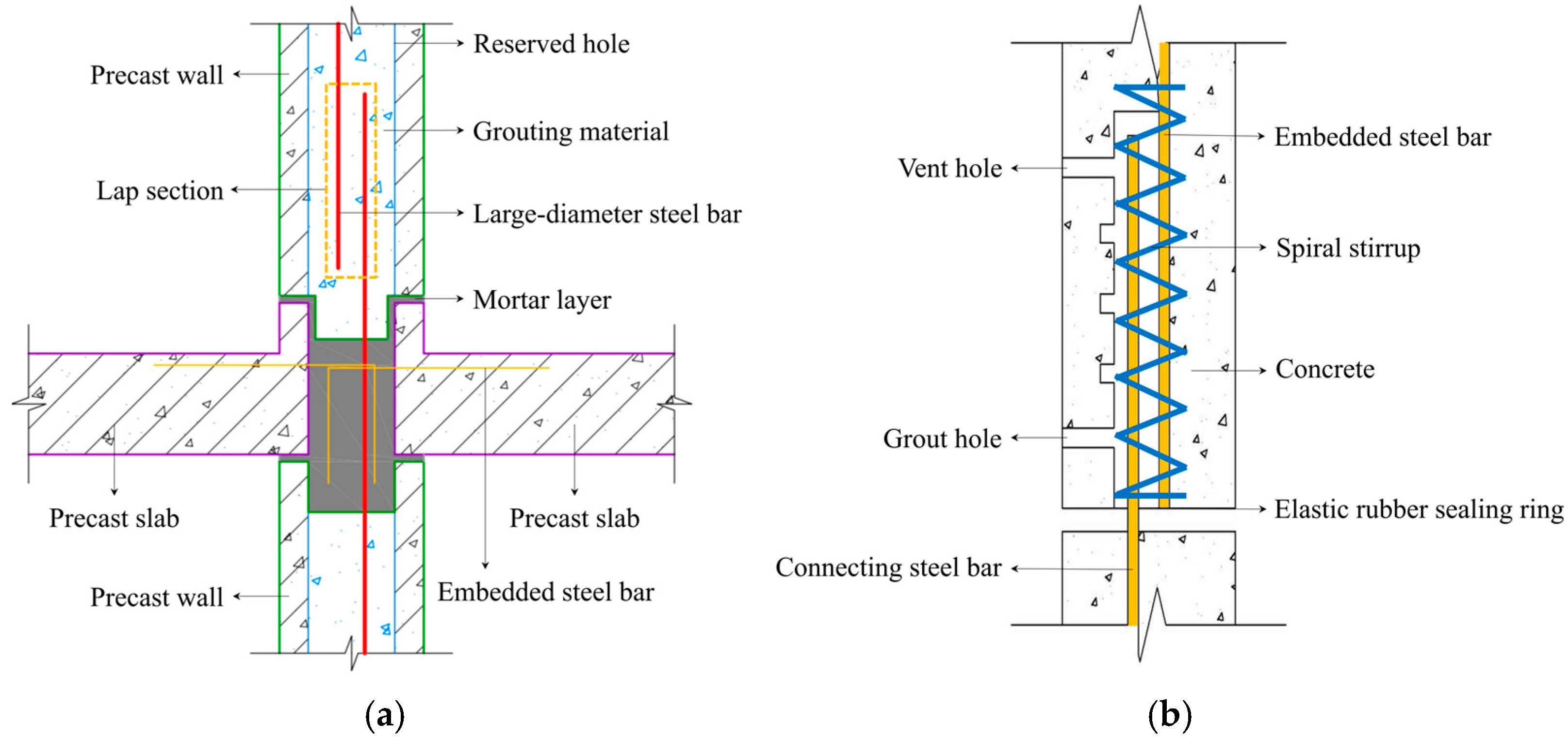
1. Introduction
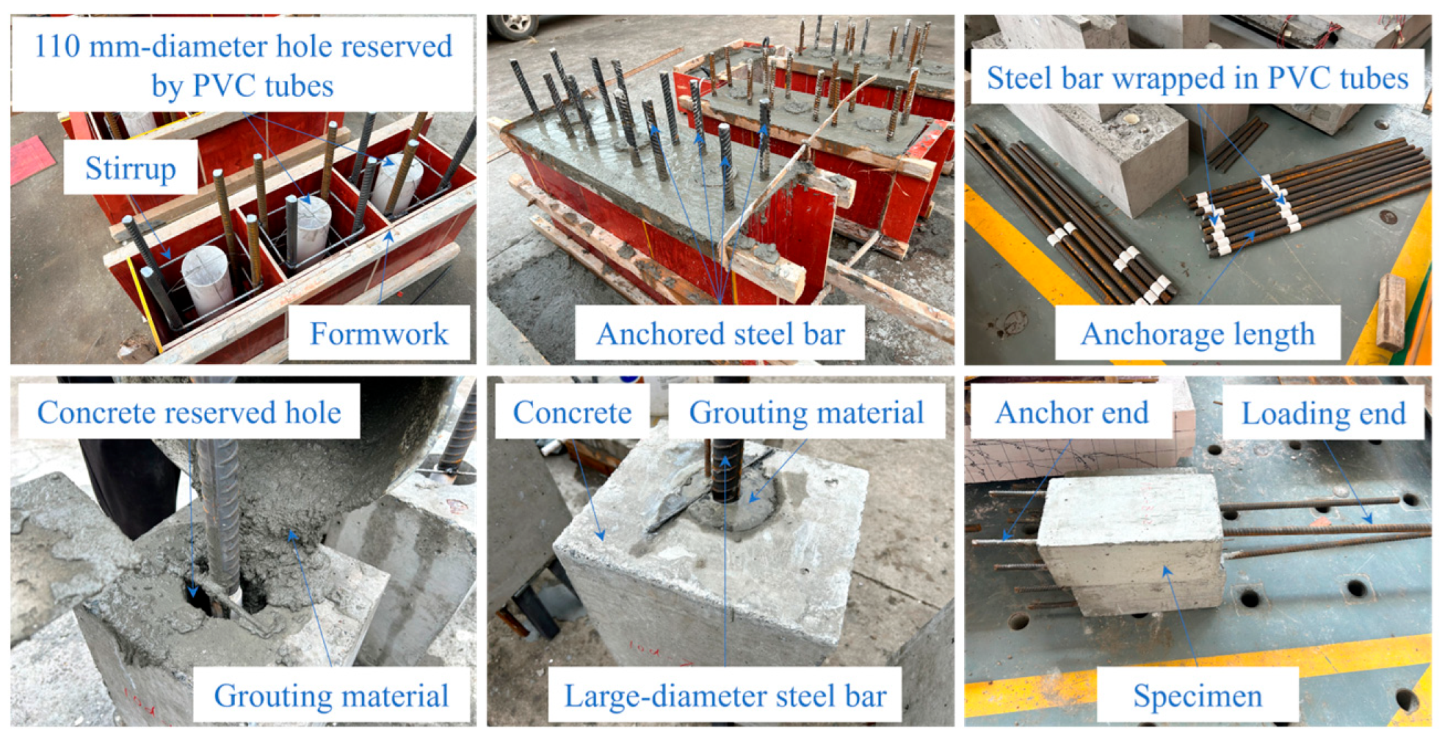
2. Experimental Program
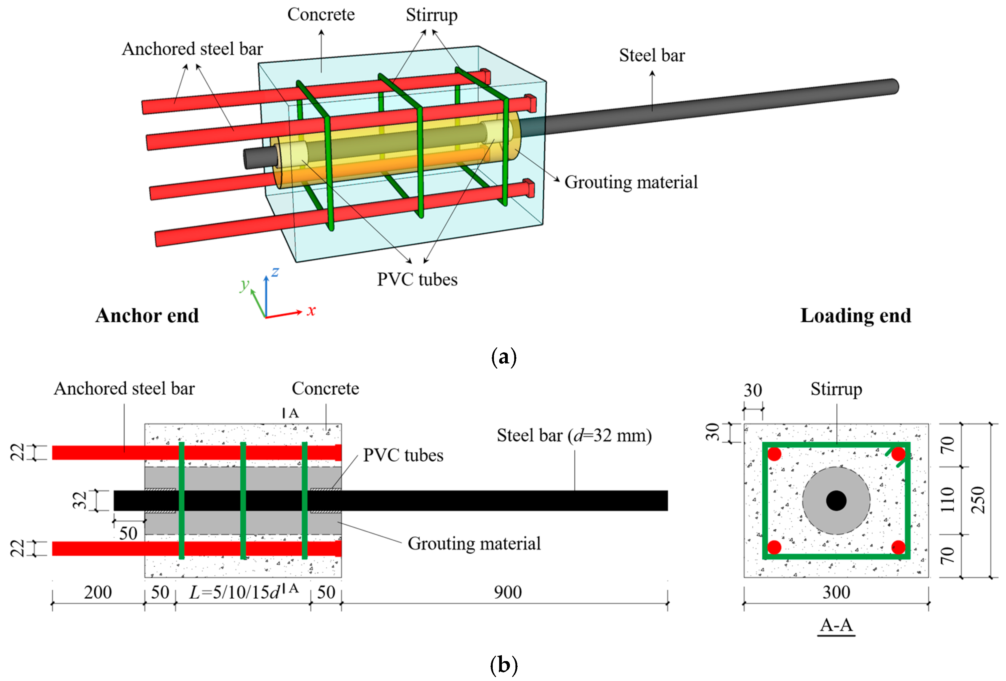
2.1. Test Specimens
2.2. Materials
2.3. Pull-Out Tests
3. Results and Discussion
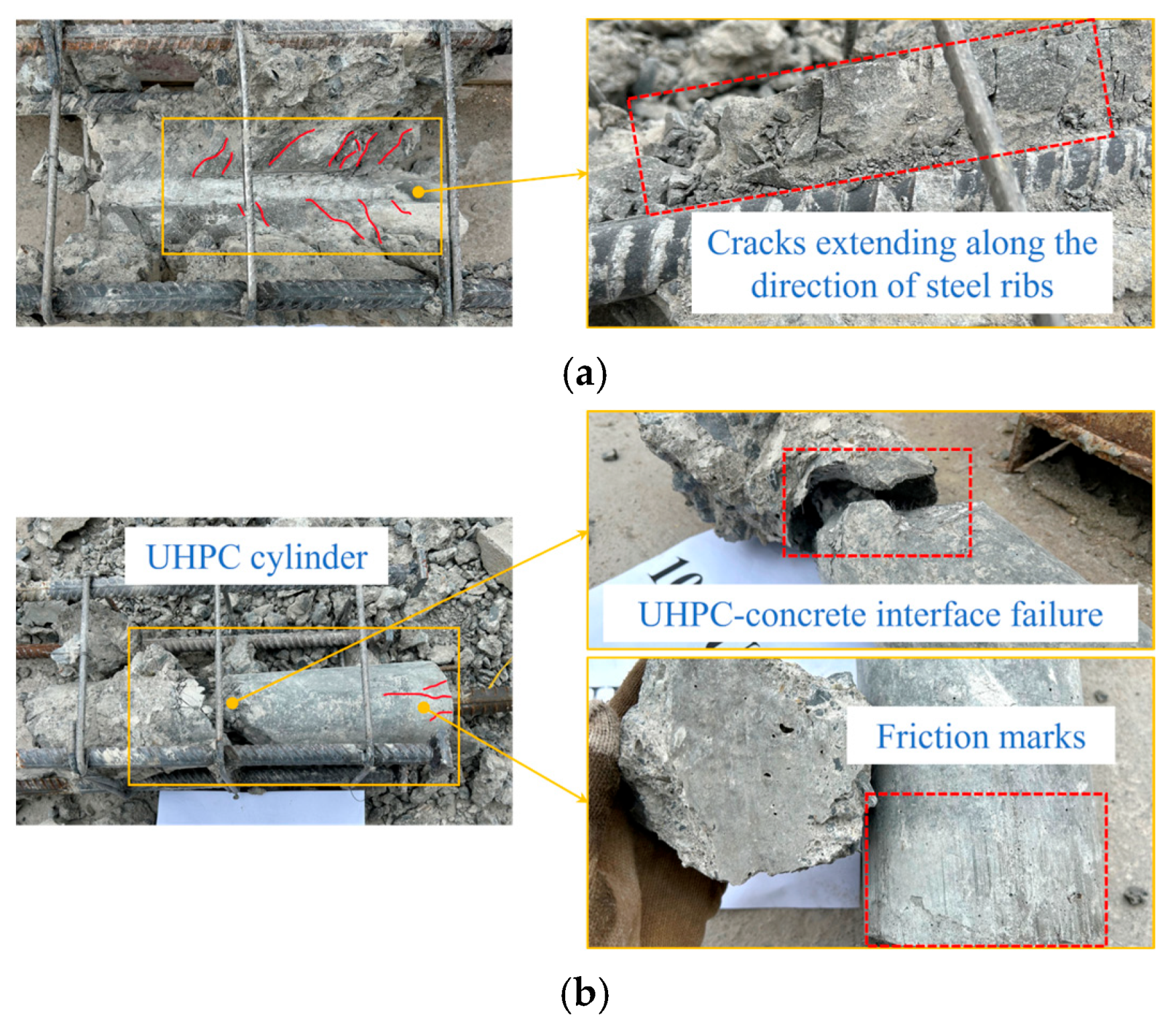
3.1. Failure Mode
3.1.1. Test Phenomena
- (a)
- Splitting-steel bar pull-out failure (SPF)
- (b)
- UHPC-concrete interface failure (UCF)
3.1.2. Internal Damage
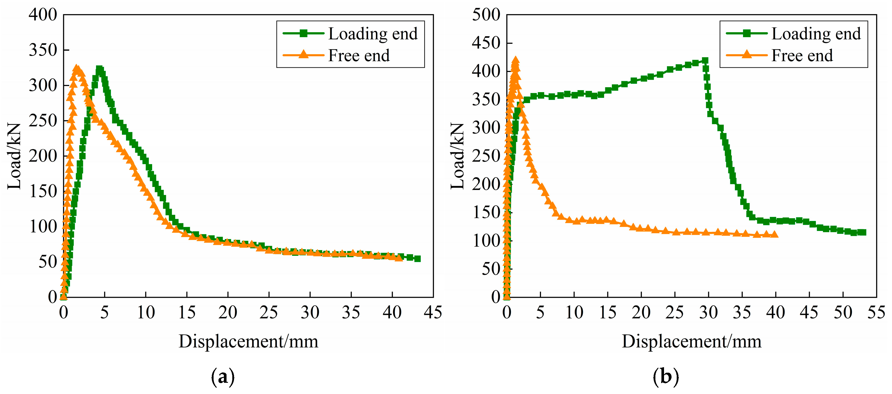
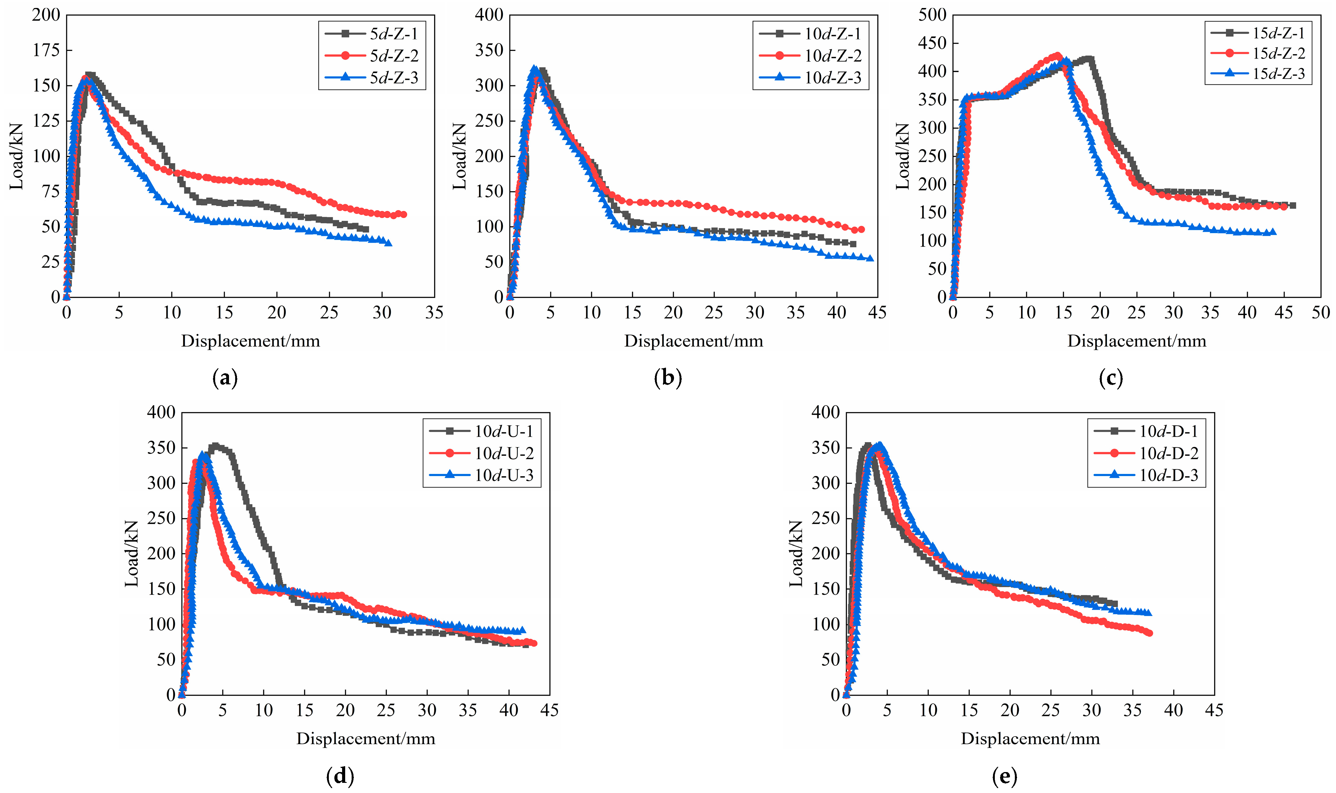
3.2. Load–Displacement Curves
3.3. Bond Strength
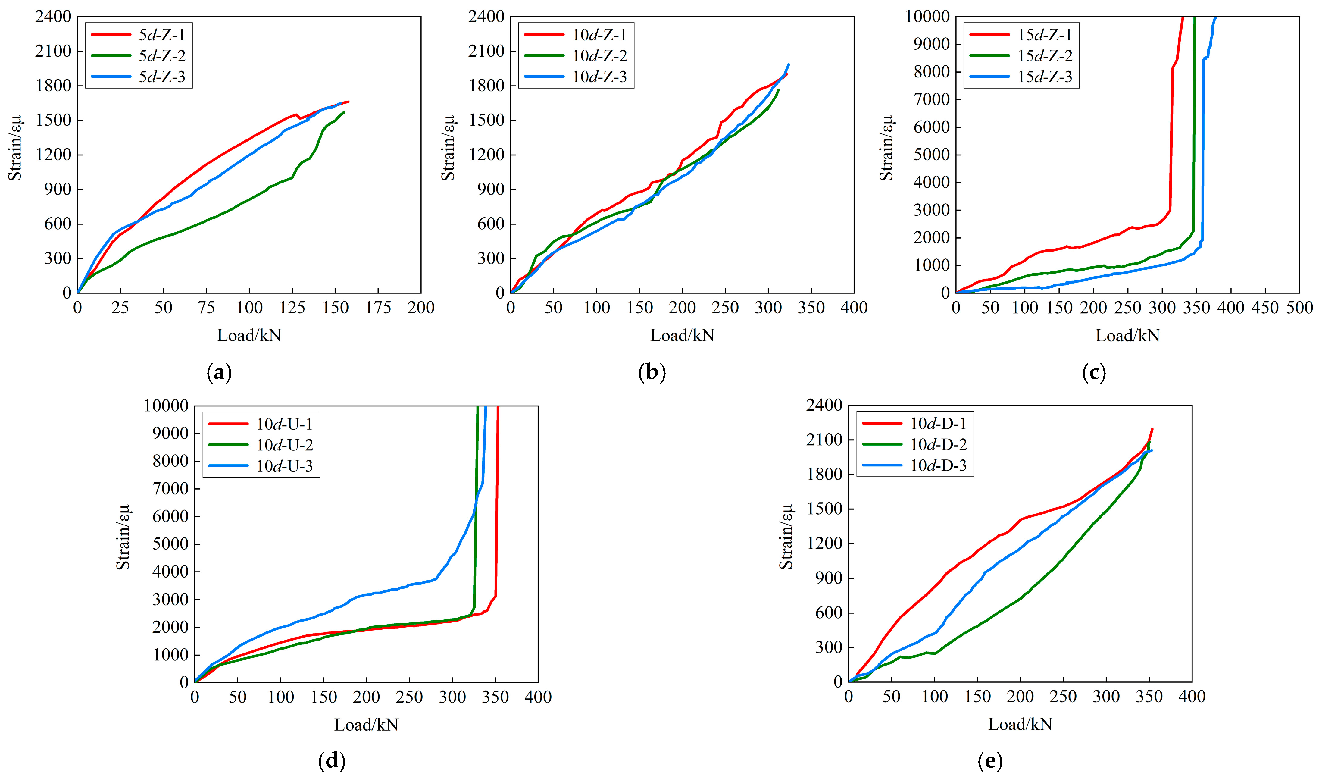
3.4. Strain of the Steel Bar
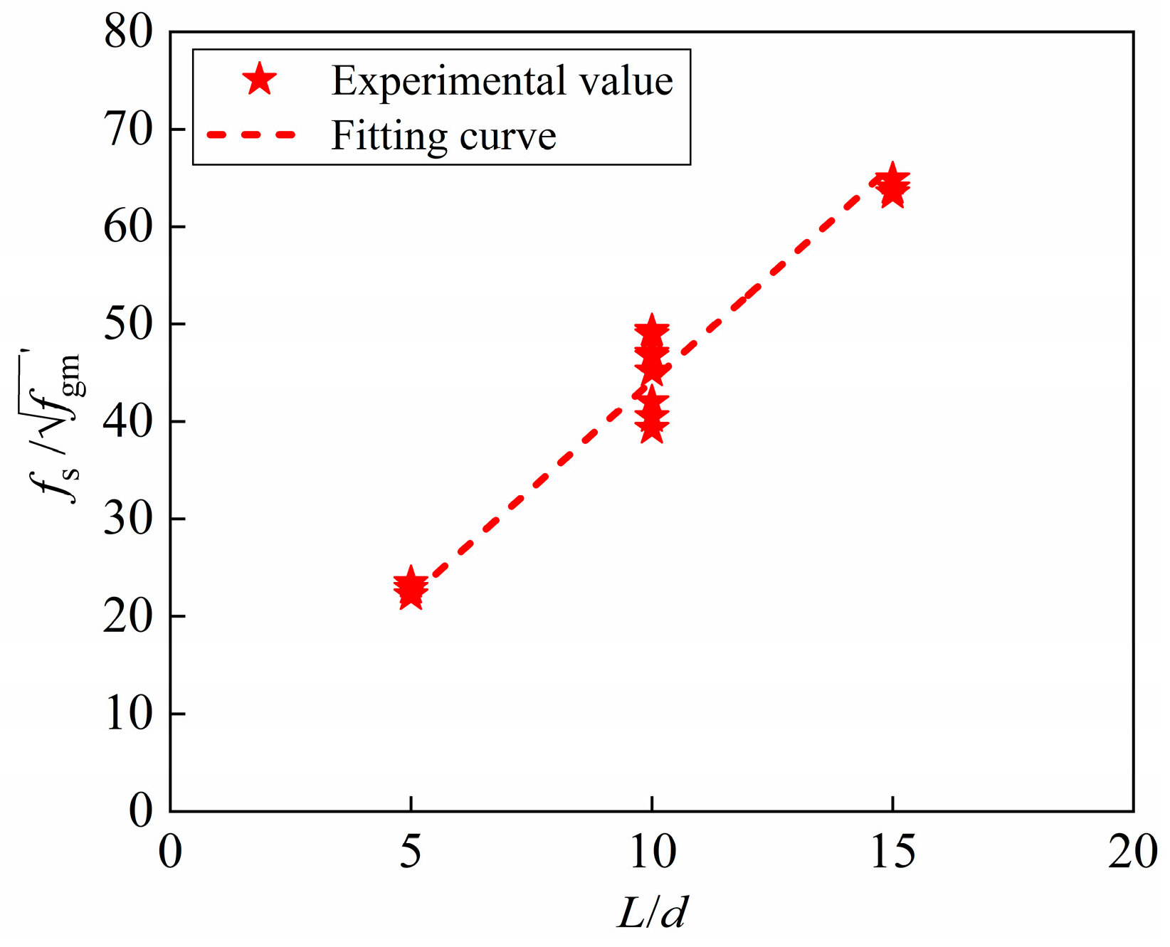
4. Calculation of Anchorage Length
4.1. Critical Anchorage Length and Ultimate Anchorage Length
- (1)
- L < lcr, the steel bars have not reached the yield strength but SPF or UCF has occurred;
- (2)
- lcr ≤ L < lu, the steel bars have reached yield strength and SPF or UCF has occurred;
- (3)
- L ≥ lu, the steel bars have reached ultimate tensile strength and broken.
4.2. Comparison of Minimum Anchorage Length
5. Conclusions
- (1)
- When the grouting material is SCC or BSGM, the failure mode is primarily splitting-steel bar pull-out failure. When the grouting material is UHPC, the failure mode changes to UHPC-concrete interface failure, and the anchorage performance between UHPC and steel bar is good without relative slip.
- (2)
- With the increase in anchorage length, the ultimate bond strength first increases and then decreases. When the anchorage length is 10d, the ultimate bond strength is the largest, and the anchorage performance is the best. In addition, the increasing of the grouting material strength can also enhance the ultimate bond strength to a certain extent.
- (3)
- The calculation formulae for the critical and ultimate anchorage length of the innovative assembled joint with large-diameter steel bar grout lapping in concrete reserved holes are proposed. The calculation results are in good agreement with the failure mode and the steel bar strain changes, which verifies the applicability and reliability.
- (4)
- When the anchored steel bar is HRB400 with a diameter not less than 20 mm, the recommended minimum anchorage length is 15.0d~18.3d. When the grouting material strength exceeds 100 MPa, the minimum anchorage length should not be less than 15.0d. The minimum anchorage length given in this paper is smaller than the recommended valve of specifications, indicating that the anchorage performance of the innovative assembled joint is satisfactory.
Author Contributions
Funding
Institutional Review Board Statement
Informed Consent Statement
Data Availability Statement
Conflicts of Interest
Abbreviations
| Abbreviations | |
| SCC | Self-compacting concrete |
| UHPC | Ultra-high performance concrete |
| BSGM | Bean-stone grouting material |
| PVC | Polyvinyl chloride |
| LVDT | Linear variable displacement transducer |
| Nomenclature | |
| d | diameter of steel bar |
| L | anchorage length |
| fc | compressive strength |
| τ | ultimate bond strength |
| τavg | average value of ultimate bond strength |
| F | ultimate tensile force of steel bar |
| Favg | average value of ultimate tensile force of steel bar |
| ΔSL | elongation deformation of steel bar |
| lw | free extension length of steel bar |
| Es | elastic modulus |
| As | cross-sectional area of steel bar |
| SL | slip of loading end |
| slip read by LVDT-3 | |
| S | relative slip |
| Savg | average value of relative slip |
| SF | slip of free end |
| lcr | critical anchorage length |
| k | correlation coefficient |
| measured value of grouting material strength | |
| lu | ultimate anchorage length |
| lmin | minimum anchorage length |
| fgm | cube compressive strength of grouting material |
| α | shape coefficient of steel bar |
| ft | tensile strength |
| ψt | position coefficient of steel bar |
| ψe | coating coefficient of steel bar |
| λ | coefficient of lightweight aggregate concrete |
References
- Guri, M.; Brzev, S.; Lluka, D. Performance of Prefabricated Large Panel Reinforced Concrete Buildings in the November 2019 Albania Earthquake. J. Earthq. Eng. 2021, 26, 5799–5825. [Google Scholar] [CrossRef]
- Romero, A.; Moustafa, M. Shake table tests of economical precast ultra-high performance concrete bridge piers with different fiber types and seismic joint materials. Eng. Struct. 2025, 330, 119961. [Google Scholar] [CrossRef]
- Sun, C.; Zhuang, M.L.; Wang, Z.; Chen, B.; Gao, L.; Qiao, Y.; Zhu, H.; Zhang, W.; Yang, J.; Yu, C. Experimental investigation on the seismic performance of prefabricated fiber-reinforced concrete beam-column joints using grouted sleeve connections. Struct. Concr. 2020, 24, 4329–5640. [Google Scholar] [CrossRef]
- Esmaeili, J.; Khoshkanabi, S.P.; Andalibi, K.; Kasaei, J. An innovative method for improving the cyclic performance of concrete beams retrofitted with prefabricated basalt-textile-reinforced ultra-high performance concrete. Structures 2023, 52, 813–823. [Google Scholar] [CrossRef]
- Sui, L.; Fan, S.; Huang, Z.; Zhang, W.; Zhou, Y.; Ye, J. Load transfer mechanism of an unwelded, unbolted, grouted connection for prefabricated square tubular columns under axial loads. Eng. Struct. 2020, 222, 111088. [Google Scholar] [CrossRef]
- Wu, C.; Liu, J.; Shi, W. Seismic performance of composite joints between prefabricated steel-reinforced concrete columns and steel beams: Experimental study. Bull. Earthq. Eng. 2020, 18, 3817–3841. [Google Scholar] [CrossRef]
- Yang, Y.; Liao, F.; Tao, Z.; Zhang, C.; Gao, X. Compressive and flexural behavior of prefabricated concrete-filled steel tubular columns with bolted splices. J. Constr. Steel Res. 2022, 188, 107048. [Google Scholar] [CrossRef]
- Liao, X.; Zhang, S.; Cao, Z.; Xiao, X. Seismic performance of a new type of precast shear walls with non-connected vertical distributed reinforcement. J. Build. Eng. 2021, 44, 103219. [Google Scholar] [CrossRef]
- Malla, P.; Xiong, F.; Cai, G.; Xu, Y.; Larbi, A.S.; Chen, W. Numerical study on the behaviour of vertical bolted joints for precast concrete wall-based low-rise buildings. J. Build. Eng. 2021, 33, 101529. [Google Scholar] [CrossRef]
- Cao, D.; Pan, Z.; Zhang, Z.; Zeng, B. Study on non-destructive testing method of grouting sleeve compactness with wavelet packet energy ratio change. Constr. Build. Mater. 2023, 389, 131767. [Google Scholar] [CrossRef]
- Hofer, L.; Zanini, M.A.; Faleschini, F.; Toska, K.; Pellegrino, C. Seismic behavior of precast reinforced concrete column-to-foundation grouted duct connections. Bull. Earthq. Eng. 2021, 19, 5191–5218. [Google Scholar] [CrossRef]
- Guo, X.; Zhang, Y.; Xiong, Z.; Xiang, Y. Load-bearing capacity of occlusive high-strength bolt connections. J. Constr. Steel. Res. 2016, 127, 1–14. [Google Scholar] [CrossRef]
- Zhang, P.; Yu, J.; Pang, Y.; Fan, J.; Guo, H.; Pan, Z. Experimental study on the mechanical properties of grouted sleeve joint with the fiber-reinforced grouting material. J. Build. Eng. 2021, 41, 102691. [Google Scholar] [CrossRef]
- Zheng, G.; Kuang, Z.; Xiao, J.; Pan, Z. Mechanical performance for defective and repaired grouted sleeve connections under uniaxial and cyclic loadings. Constr. Build. Mater. 2020, 233, 117233. [Google Scholar] [CrossRef]
- Liu, J.; Li, D.; Cui, X. Research status and future directions of defect detection in grouted splice sleeves: A review. Constr. Build. Mater. 2023, 402, 133010. [Google Scholar] [CrossRef]
- Wan, L.; Zhao, Y.; Yu, M.; Li, N.; Sun, X. Experimental study on spatial mechanical properties of grout anchor lap joints. Structures 2022, 44, 728–739. [Google Scholar] [CrossRef]
- Zheng, Y.; Zhu, Z.; Guo, Z.; Liu, P. Behavior and Splice Length of Deformed Bars Lapping in Spirally Confined Grout-Filled Corrugated Duct. Adv. Mater. Sci. Eng. 2019, 2019, 5280986. [Google Scholar] [CrossRef]
- Ma, C.; Jiang, H.; Wang, Z. Experimental investigation of precast RC interior beam-column-slab joints with grouted spiral-confined lap connection. Eng. Struct. 2019, 196, 109317. [Google Scholar] [CrossRef]
- Chen, J.; Chen, X.; Ding, F.; Xiang, P.; Yang, C.; Liu, Y.; Xu, F. Mechanical performance of overlap connections with grout-filled anchor reinforcements in embedded metal corrugated pipe. Arch. Civ. Mech. Eng. 2020, 20, 128. [Google Scholar] [CrossRef]
- Liu, F.; Qian, H.; Zhang, Z.; Zhang, H. Experimental Study on the Mechanical Properties of Vertical Corrugated Pipe Grout Anchor Connection Joints. Appl. Sci. 2023, 13, 11889. [Google Scholar] [CrossRef]
- Roeder, C.W. Connection Performance for Seismic Design of Steel Moment Frames. J. Struct. Eng. 2002, 128, 517–525. [Google Scholar] [CrossRef]
- Luo, X.; He, Y.; Chen, Q.; Chen, L. Study on Joint Connection Performance of an Innovative Tooth Groove Connection and Vertical Reinforcement Lapping in Reserved Hole. Materials 2023, 16, 7371. [Google Scholar] [CrossRef] [PubMed]
- El-Khier, M.; Morcous, G. Precast concrete deck-to-girder connection using Ultra-High Performance Concrete (UHPC) shear pockets. Eng. Struct. 2021, 248, 113082. [Google Scholar] [CrossRef]
- Gao, Q.; Li, J.H.; Qiu, Z.J.; Hwang, H.J. Cyclic loading test for interior precast SRC beam-column joints with and without slab. Eng. Struct. 2019, 182, 1–12. [Google Scholar] [CrossRef]
- Ge, Q.; Meng, Y.J.; Ai, J.S.; Zuo, W.H.; Xiong, F.; Liu, Y.; Dong, N. Seismic performance of precast concrete sandwich walls with bolt-steel plate connection. Eng. Struct. 2024, 303, 117402. [Google Scholar] [CrossRef]
- Li, F.R.; Abruzzese, D.; Milani, G.; Li, S.C. Influence of internal defects of semi grouted sleeve connections on the seismic performance of precast monolithic concrete columns. J. Build. Eng. 2022, 49, 104009. [Google Scholar] [CrossRef]
- Li, D.; Liu, H. Detection of sleeve grouting connection defects in fabricated structural joints based on ultrasonic guided waves. Smart. Mater. Struct. 2019, 28, 085033. [Google Scholar] [CrossRef]
- Cao, D.; Pan, Z.; Zhen, G. Effects of grouting defects on seismic behavior of full-scale precast reinforced concrete shear wall. J. Build. Eng. 2023, 76, 107216. [Google Scholar] [CrossRef]
- Elsayed, M.; Nehdi, M.L.; Provost-Smith, D.J.; Eissa, O.S. Exploratory investigation of grouted bar-in-duct connections under direct tensile load. Constr. Build. Mater. 2018, 183, 311–324. [Google Scholar] [CrossRef]
- Tazarv, M.; Saiidi, M.S. Design and construction of UHPC-filled duct connections for precast bridge columns in high seismic zones. Struct. Infrastruct. Eng. 2017, 13, 743–753. [Google Scholar] [CrossRef]
- Chen, J.; Zhao, C.; Ding, F.; Duan, Q.; Cao, Z.; Xu, F.; Yang, C.; Lu, D.; Xiang, P. Mechanical performance of the grouted lapped double reinforcements anchored in embedded corrugated sleeves. Structures 2020, 28, 1354–1365. [Google Scholar] [CrossRef]
- Wang, H.; Liang, R.; Li, J.; Liu, J.; Li, H.; Hu, X.; Zhu, K. Anchorage performance of grouted corrugated duct connection under monotonic loading: Experimental and numerical investigation. Constr. Build. Mater. 2022, 329, 127069. [Google Scholar] [CrossRef]
- Zhou, Y.; Ou, Y.C.; Lee, G.C. Bond-slip responses of stainless reinforcing bars in grouted ducts. Eng. Struct. 2017, 141, 651–665. [Google Scholar] [CrossRef]
- Seifi, P.; Henry, R.S.; Ingham, J.M. In-plane cyclic testing of precast concrete wall panels with grouted metal duct base connections. Eng. Struct. 2019, 184, 85–98. [Google Scholar] [CrossRef]
- Popa, V.; Papurcu, A.; Cotofana, D.; Pascu, R. Experimental testing on emulative connections for precast columns using grouted corrugated steel sleeves. Bull. Earthq. Eng. 2015, 13, 2429–2447. [Google Scholar] [CrossRef]
- Tullini, N.; Minghini, F. Cyclic test on a precast reinforced concrete column-to-foundation grouted duct connection. Bull. Earthq. Eng. 2020, 18, 1657–1691. [Google Scholar] [CrossRef]
- Tullini, N.; Minghini, F. Grouted sleeve connections used in precast reinforced concrete construction-Experimental investigation of a column-to-column joint. Eng. Struct. 2016, 127, 784–803. [Google Scholar] [CrossRef]
- Aiamsri, K.; Yaowarat, T.; Horpibulsuk, S.; Suddeepong, A.; Buritatum, A.; Hiranwatthana, K.; Nitichote, K. Bonding behavior of lap-spliced reinforcing bars embedded in ultra-high-performance concrete with steel fibers. Dev. Built. Environ. 2024, 20, 100585. [Google Scholar] [CrossRef]
- Alkaysi, M.; El-Tawil, S. Factors affecting bond development between Ultra High Performance Concrete (UHPC) and steel bar reinforcement. Constr. Build. Mater. 2017, 144, 412–422. [Google Scholar] [CrossRef]
- Chen, Q.; Luo, X.; Xing, M.; Li, Z. Shaking table test of fully assembled precast concrete shear wall substructure with tooth groove connection and vertical reinforcement lapping in reserved hole. J. Build. Eng. 2023, 76, 107151. [Google Scholar] [CrossRef]
- GB/T 50081-2019; Standard for Test Methods of Concrete Physical and Mechanical Properties. China Architecture & Building Press: Beijing, China, 2019.
- Gong, W.; Chen, Q.; Miao, J. Bond behaviors between copper slag concrete and corroded steel bar after exposure to high temperature. J. Build. Eng. 2021, 44, 103312. [Google Scholar] [CrossRef]
- Jia, J.; Zhao, N.; Bai, Y.; Du, X.; Yang, K.; Yang, D. Bond-slip model for rebar mounted to high-strength grouting material. J. Build. Eng. 2023, 74, 106794. [Google Scholar] [CrossRef]
- Zhao, J.Q.; Zhou, L.; Ding, Y.G.; Zhu, R.J. Experiment on anchoring performance of spiral stirrup-corrugated pipe grout splicing. J. Jilin. Univ. (Eng. Tech. Ed.) 2023, 54, 2484–2494. (In Chinese) [Google Scholar]
- Xu, G.; Chen, B.; Zeng, J.; Gao, D.; Bao, H. Research on critical anchorage length of UHPC-CA and HTRB600E high-strength steel bars. Structures 2022, 41, 235–241. [Google Scholar] [CrossRef]
- Zhao, M.; Li, J.; Xie, Y.; Shen, J.; Li, C. Experimental study of the bond behavior of 400MPa grade hot-rolled ribbed steel bars in steel fibre reinforced concrete. Sci. Rep. 2024, 14, 4066. [Google Scholar] [CrossRef]
- GB 50010-2010; Code for Design of Concrete Structures. China Architecture & Building Press: Beijing, China, 2015.
- ACI 318-14; Building Code Requirements for Structural Concrete. American Concrete Institute: Farmington Hills, MI, USA, 2014.


| Specimen | d/mm | L/mm | Dimension/mm | Grouting Material |
|---|---|---|---|---|
| 5d-Z | 32 | 5d = 160 | 250 × 300 × 260 | Self-compacting concrete (SCC) |
| 10d-Z | 32 | 10d = 320 | 250 × 300 × 420 | Self-compacting concrete (SCC) |
| 15d-Z | 32 | 15d = 480 | 250 × 300 × 580 | Self-compacting concrete (SCC) |
| 10d-U | 32 | 10d = 320 | 250 × 300 × 420 | Ultra-high performance concrete (UHPC) |
| 10d-D | 32 | 10d = 320 | 250 × 300 × 420 | Bean-stone grouting material (BSGM) |
| Grade | d/mm | Yield Strength/MPa | Tensile Strength/MPa | Elongation/% |
|---|---|---|---|---|
| HRB400 | 32 | 434.60 | 633.31 | 30.25 |
| HRB400 | 32 | 433.38 | 632.58 | 26.63 |
| HRB400 | 32 | 430.87 | 631.93 | 29.38 |
| Grouting Material | Load/kN | fc/MPa |
|---|---|---|
| SCC | 711.05 | 67.55 |
| UHPC | 1149.26 | 109.18 |
| BSGM | 836.53 | 79.47 |
| Specimen | L/mm | F/kN | Favg/kN | τ/MPa | τavg/MPa | SL/mm | SF/mm | S/mm | Savg/mm | Failure Mode |
|---|---|---|---|---|---|---|---|---|---|---|
| 5d-Z-1 | 160 | 157.70 | 155.30 | 9.81 | 9.66 | 2.53 | 1.63 | 2.08 | 1.91 | SPF |
| 5d-Z-2 | 160 | 155.10 | 9.65 | 2.30 | 1.20 | 1.75 | SPF | |||
| 5d-Z-3 | 160 | 153.10 | 9.52 | 2.40 | 1.40 | 1.90 | SPF | |||
| 10d-Z-1 | 320 | 321.60 | 319.03 | 10.00 | 9.92 | 6.31 | 1.69 | 4.00 | 3.40 | SPF |
| 10d-Z-2 | 320 | 311.80 | 9.70 | 5.20 | 1.30 | 3.25 | SPF | |||
| 10d-Z-3 | 320 | 323.70 | 10.07 | 4.35 | 1.55 | 2.95 | SPF | |||
| 15d-Z-1 | 480 | 422.50 | 423.43 | 8.33 | 8.40 | / | / | / | / | SPF |
| 15d-Z-2 | 480 | 428.60 | 8.33 | / | / | / | SPF | |||
| 15d-Z-3 | 480 | 419.20 | 8.54 | / | / | / | SPF | |||
| 10d-U-1 | 320 | 353.20 | 341.07 | 10.98 | 10.60 | 6.23 | 1.95 | 4.09 | 2.75 | UCF |
| 10d-U-2 | 320 | 330.00 | 10.26 | 3.15 | 0.25 | 1.70 | UCF | |||
| 10d-U-3 | 320 | 340.00 | 10.57 | 3.68 | 1.25 | 2.47 | UCF | |||
| 10d-D-1 | 320 | 353.60 | 352.40 | 11.00 | 10.96 | 4.06 | 1.24 | 2.65 | 3.48 | SPF |
| 10d-D-2 | 320 | 350.40 | 10.90 | 5.50 | 1.90 | 3.70 | SPF | |||
| 10d-D-3 | 320 | 353.20 | 10.98 | 6.31 | 1.89 | 4.10 | SPF |
| Grouting Material | /MPa | lcr/mm | lu/mm |
|---|---|---|---|
| SCC | 67.55 | 11.9d | 17.3d |
| UHPC | 109.18 | 9.3d | 13.6d |
| BSGM | 79.47 | 10.9d | 16.0d |
Disclaimer/Publisher’s Note: The statements, opinions and data contained in all publications are solely those of the individual author(s) and contributor(s) and not of MDPI and/or the editor(s). MDPI and/or the editor(s) disclaim responsibility for any injury to people or property resulting from any ideas, methods, instructions or products referred to in the content. |
© 2025 by the authors. Licensee MDPI, Basel, Switzerland. This article is an open access article distributed under the terms and conditions of the Creative Commons Attribution (CC BY) license (https://creativecommons.org/licenses/by/4.0/).
Share and Cite
Chen, Q.; Luo, X.; Deng, C.; Zhou, T.; Zheng, X. Anchorage Performance of an Innovative Assembled Joint with Large-Diameter Steel Bar Grout Lapping in Concrete Reserved Hole. Materials 2025, 18, 2950. https://doi.org/10.3390/ma18132950
Chen Q, Luo X, Deng C, Zhou T, Zheng X. Anchorage Performance of an Innovative Assembled Joint with Large-Diameter Steel Bar Grout Lapping in Concrete Reserved Hole. Materials. 2025; 18(13):2950. https://doi.org/10.3390/ma18132950
Chicago/Turabian StyleChen, Qi, Xiaoyong Luo, Chao Deng, Tai Zhou, and Xutong Zheng. 2025. "Anchorage Performance of an Innovative Assembled Joint with Large-Diameter Steel Bar Grout Lapping in Concrete Reserved Hole" Materials 18, no. 13: 2950. https://doi.org/10.3390/ma18132950
APA StyleChen, Q., Luo, X., Deng, C., Zhou, T., & Zheng, X. (2025). Anchorage Performance of an Innovative Assembled Joint with Large-Diameter Steel Bar Grout Lapping in Concrete Reserved Hole. Materials, 18(13), 2950. https://doi.org/10.3390/ma18132950