
Engineering Characteristics of Dredged Sediment Solidified by MSWI FA and Cement Under Different Curing Conditions


Abstract
1. Introduction
2. Experimental Materials and Methods
2.1. Experimental Materials
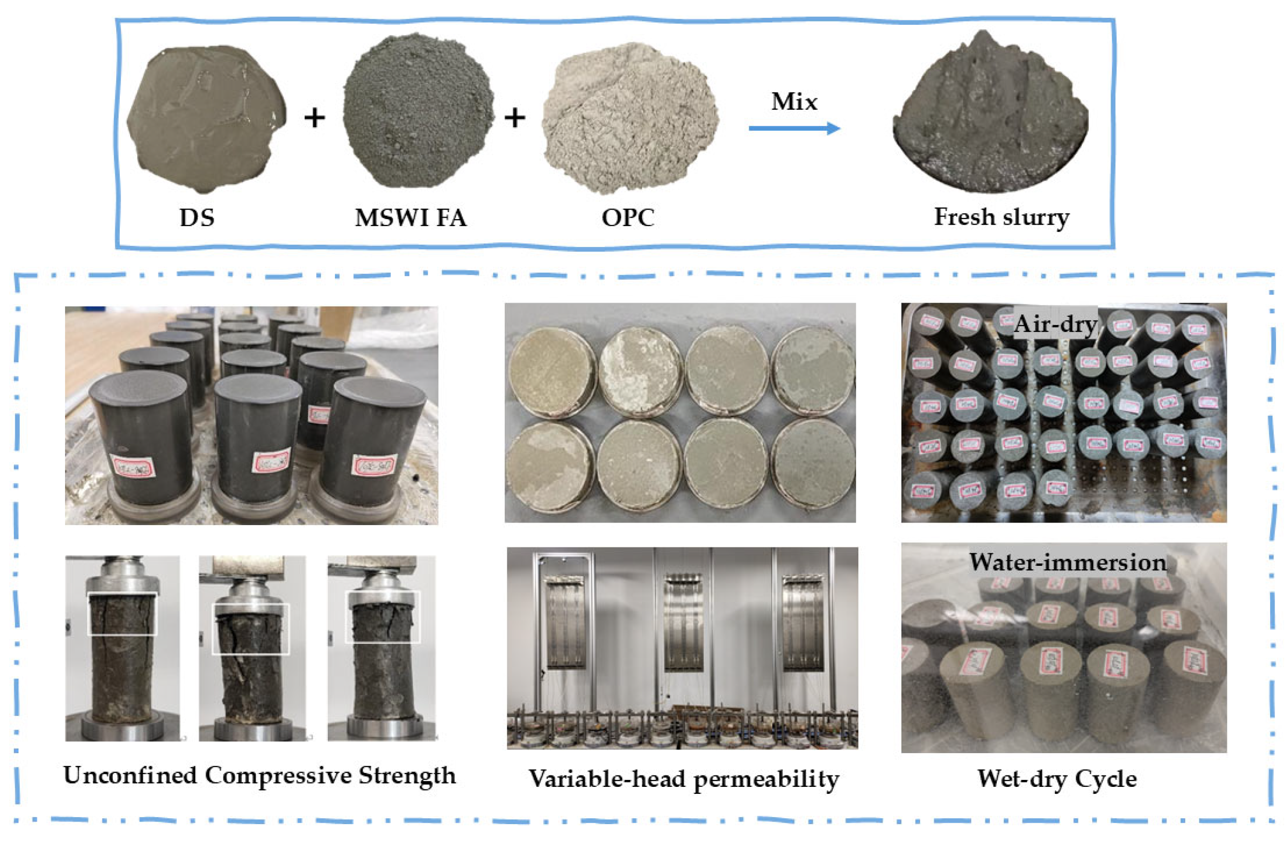
2.2. Sample Preparation
2.3. Experimental Methods
2.3.1. Unconfined Compressive Strength Tests
2.3.2. Variable-Head Permeability Tests
2.3.3. Wet–Dry Cycle Tests
2.3.4. X-Ray Diffraction (XRD)
2.3.5. Scanning Electron Microscopy (SEM)
3. Results
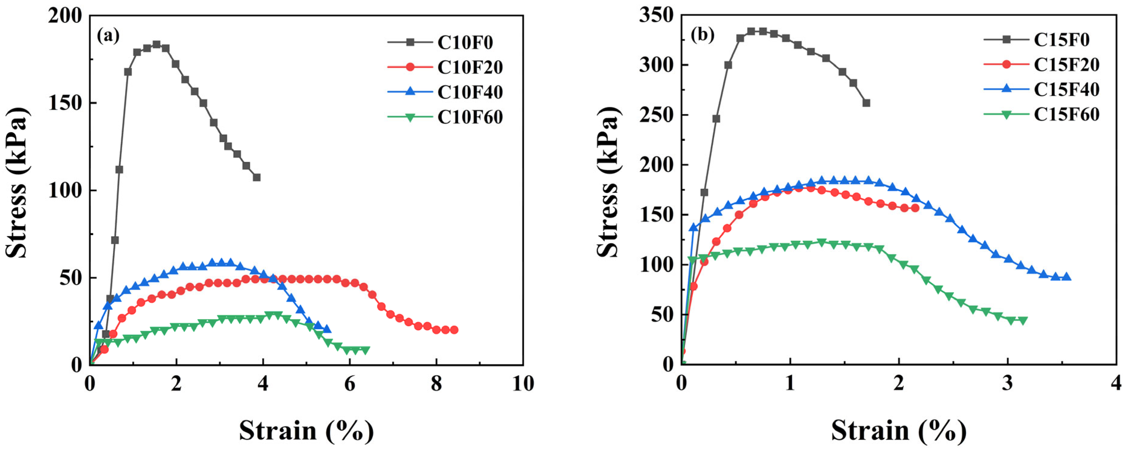
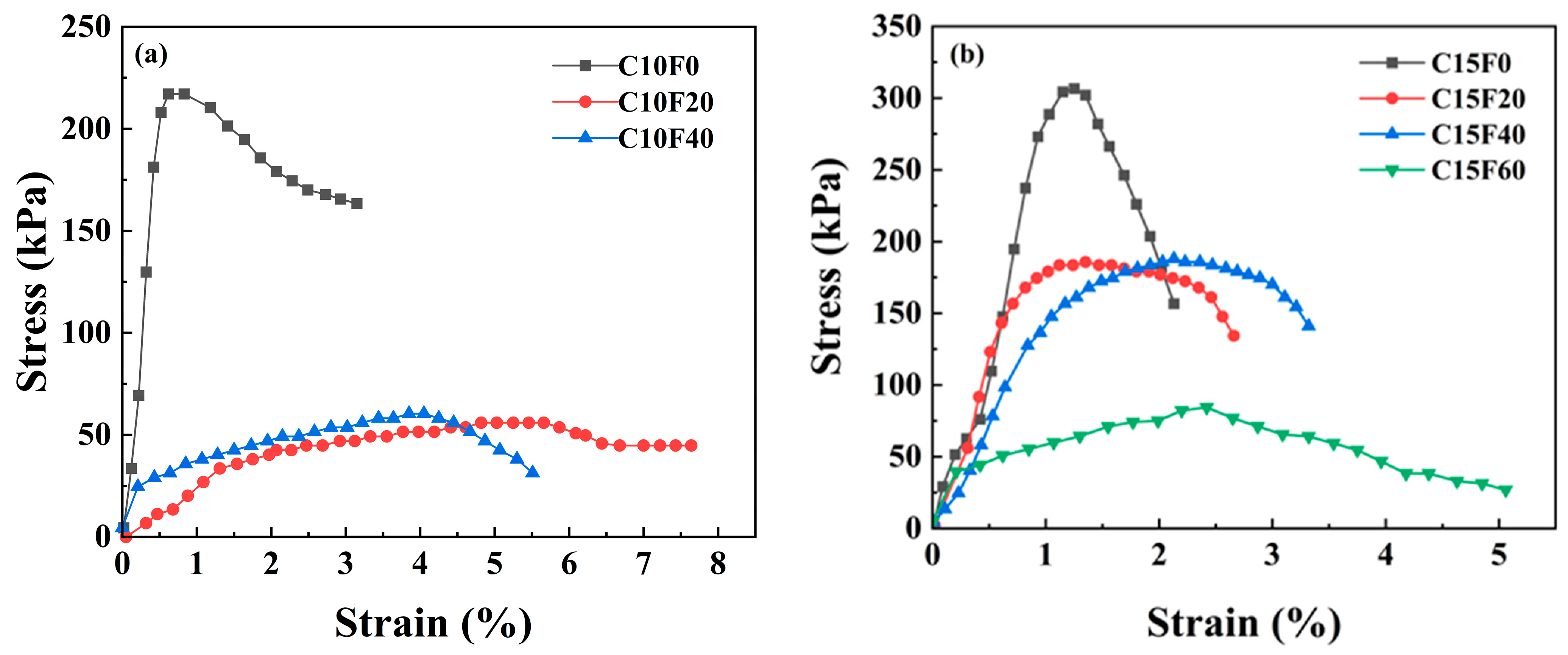
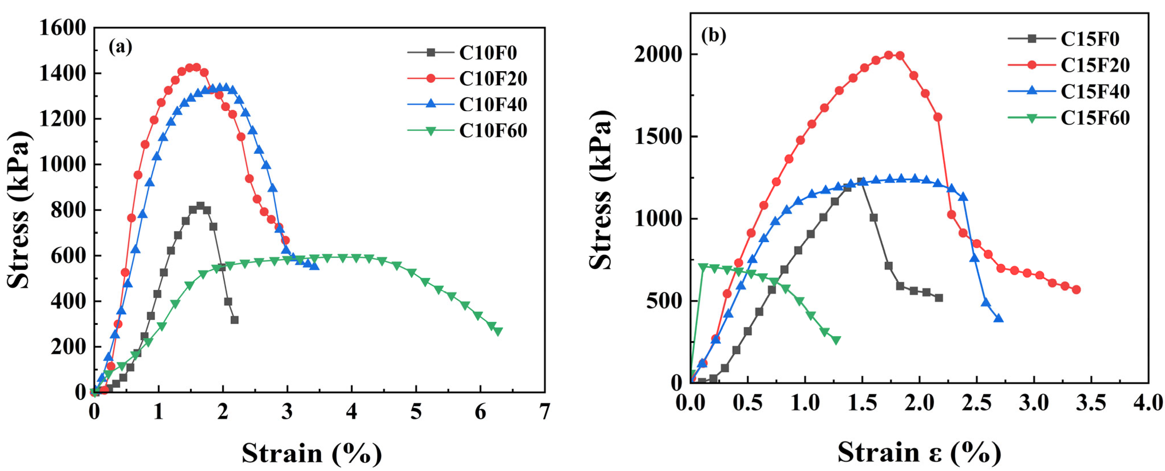
3.1. Mechanical Properties
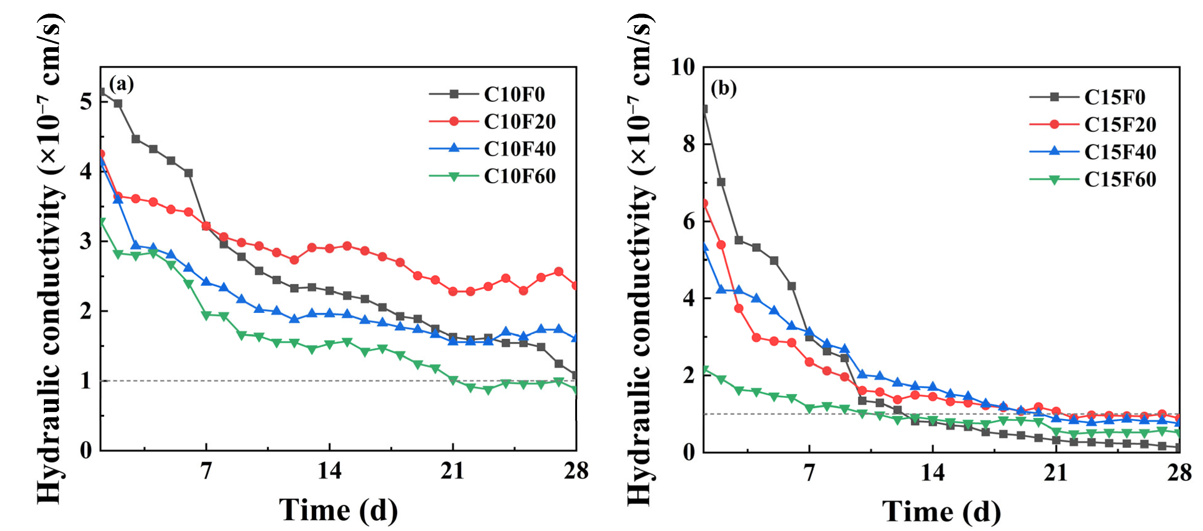
3.2. Permeability
3.3. Wet–Dry Durability
3.4. Crystalline Phases
3.5. Micromorphology
4. Discussion
5. Conclusions
- (1)
- Curing conditions and material ratios jointly govern mechanical performance. Under natural curing, appropriate FA content promoted cementitious reactions, with the C15F20 specimen achieving a peak UCS of 1993.9 kPa (62.6% higher than the pure cement group). However, excessive FA (≥40%) caused abrupt strength reduction. Under standard or underwater curing, FA incorporation reduced strength but improved deformation performance, though increasing the OPC dosage from 10% to 15% restored strength. This indicates that FA’s effect on strength is condition-dependent, and its optimal dosage must be determined holistically based on curing environment requirements.
- (2)
- The OPC content is a key factor in controlling the permeability coefficient. When the OPC content was 10%, regardless of whether the MSWI FA content is 0%, 20%, or 40%, the permeability coefficient of the samples is higher than 10−7 cm/s, which does not meet the requirements for landfill cover materials; however, when the OPC content is increased to 15%, the permeability coefficients under all FA contents dropped below 10−7 cm/s, with the permeability coefficient of C15F20 being 0.88 × 10⁻⁷ cm/s, meeting the U.S. EPA standards.
- (3)
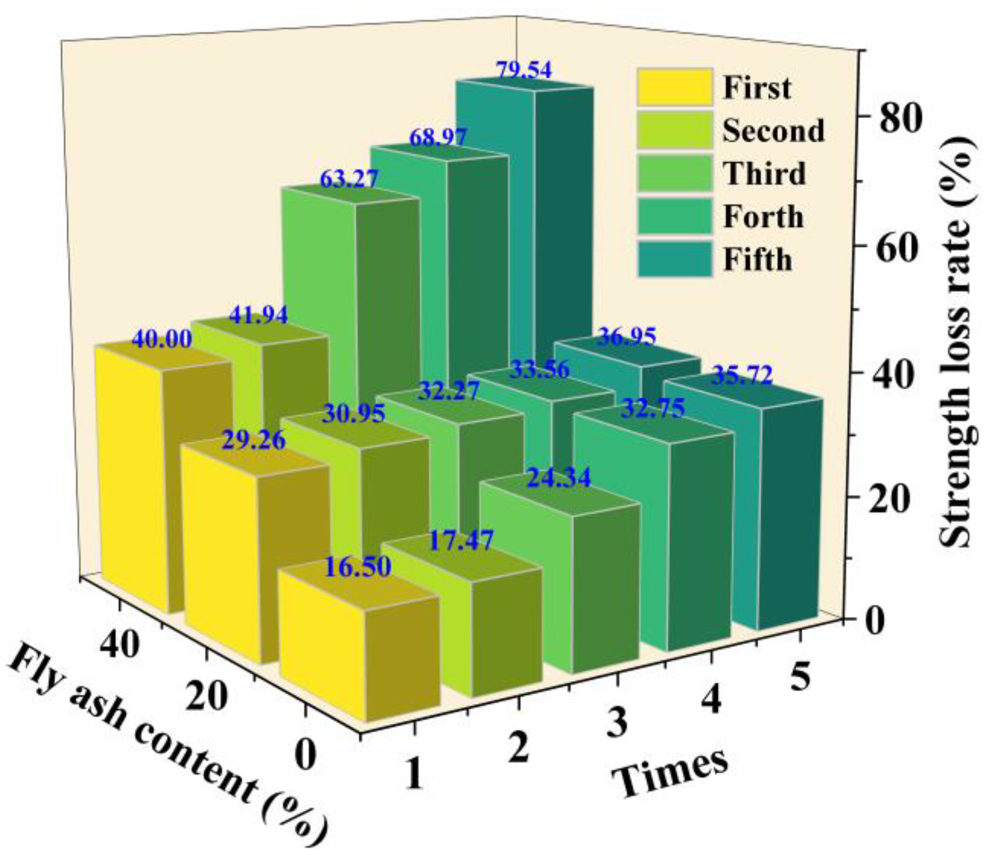
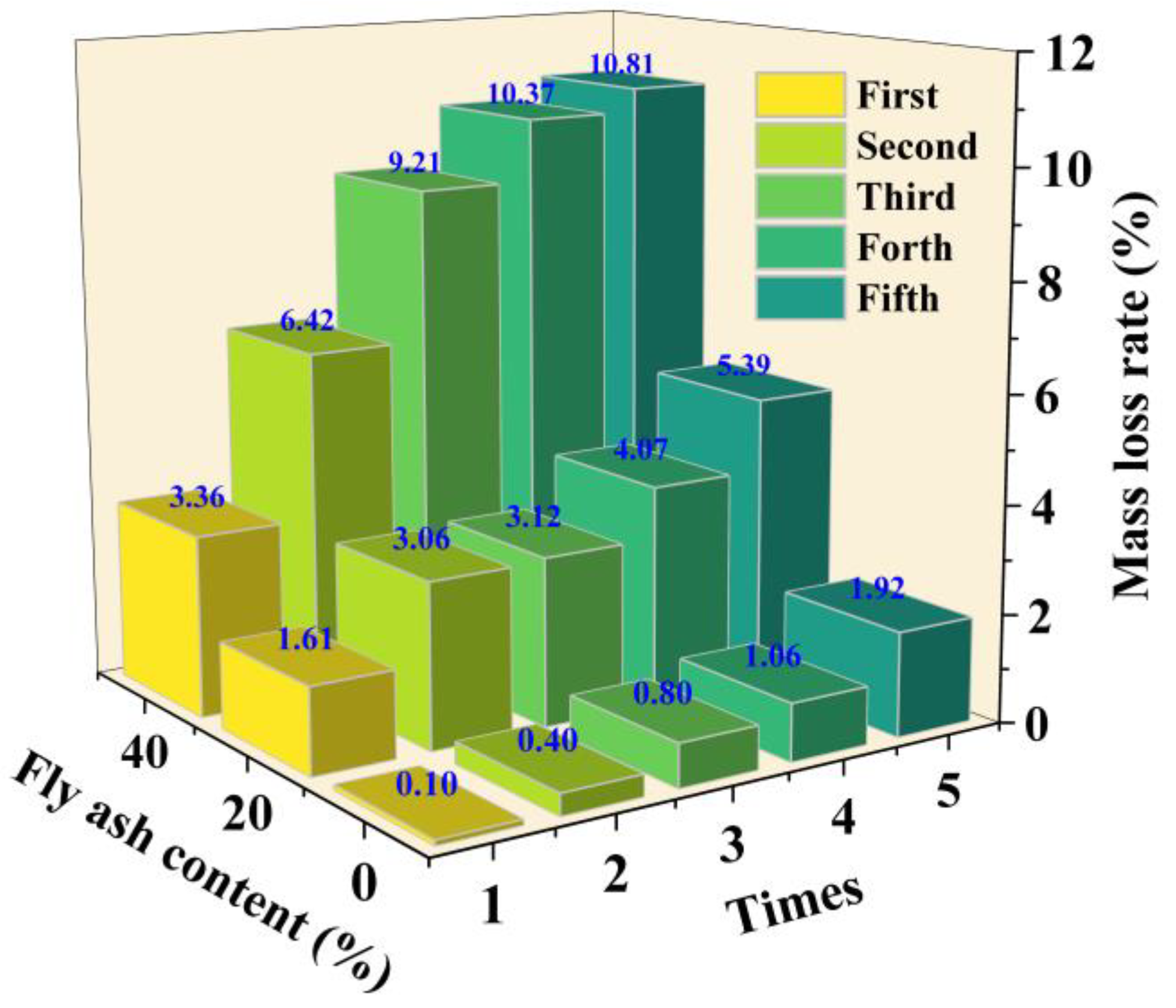
- Under wet–dry cycling, the strength and mass loss rate of solidified sediment increased significantly with higher FA content. At 10% OPC dosage, specimens with 0%, 20%, and 40% FA exhibited strength loss rates exceeding 35.72%, 36.95%, and 79.54% after five cycles, respectively, and mass loss rates reaching 1.92%, 5.39%, and 10.81%. Results indicate that FA content critically affected material durability under wet–dry cycles, and high dosages (≥20%) significantly reduced engineering service life.
- (4)
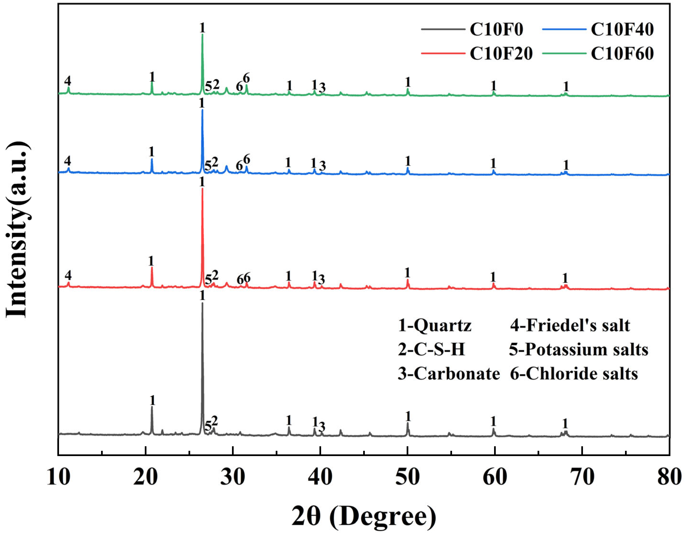
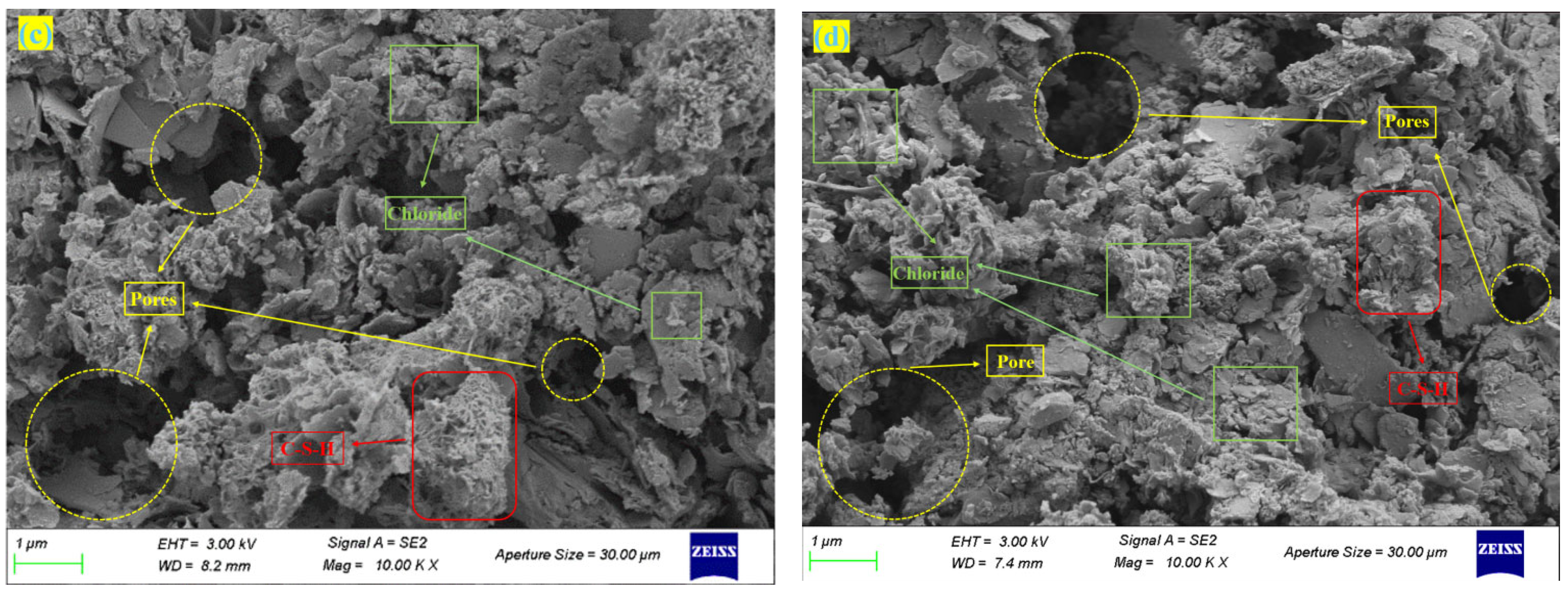
- As MSWI FA content increased, C-S-H gel formation was inhibited by chloride salts, resulting in higher porosity and looser structure of the solidified body. At 60% MSWI FA dosage, free chloride salts accumulated in pores, forming micron-scale aggregates and triggering phase separation, leading to severe microstructural degradation. XRD and SEM results confirmed that soluble salts (e. g., K+, Cl−) introduced by FA not only inhibited cementitious reactions but also exacerbated pore expansion through crystallization–dissolution cycles.
Author Contributions
Funding
Institutional Review Board Statement
Informed Consent Statement
Data Availability Statement
Conflicts of Interest
References
- Kim, E.-H.; Cho, J.-K.; Yim, S. Digested sewage sludge solidification by converter slag for landfill cover. Chemsphere 2005, 59, 387–395. [Google Scholar] [CrossRef] [PubMed]
- Xiao, Z.; Hou, B.; Chang, Z.; Wei, X.; Song, Z.; Li, H. The properties of cement stabilized dredged sludge solidifying in seawater and its application in the protection of subsea pipelines. Appl. Ocean Res. 2024, 153, 104264. [Google Scholar] [CrossRef]
- Wang, Y.; Wang, G.; Wan, Y.; Yu, X.; Zhao, J.; Shao, J. Recycling of dredged river silt reinforced by an eco-friendly technology as microbial induced calcium carbonate precipitation (MICP). Soils Found. 2022, 62, 101216. [Google Scholar] [CrossRef]
- Xu, H.; Zheng, H.; Wang, J.; Ding, X.-Q.; Chen, P. Laboratory method of microbial induced solidification/stabilization for municipal solid waste incineration fly ash. MethodsX 2019, 6, 61036–61043. [Google Scholar] [CrossRef]
- Wang, F.; Zhang, F.; Chen, Y.; Gao, J.; Zhao, B. A comparative study on the heavy metal solidification/stabilization performance of four chemical solidifying agents in municipal solid waste incineration fly ash. J. Hazard. Mater. 2015, 300, 451–458. [Google Scholar] [CrossRef]
- Jun, R.; Peng, Y.; Wang, W.-Z.; Tang, W.-Y.; Yin, H.-B.; Zhu, L.-J. [Influence of Different Types of Dewatering Agents on the Solidification Effect and Physical and Chemical Properties of sediment]. Huanjing Kexue 2022, 43, 3672–3681. [Google Scholar]
- Shan, J.L.; Yifan, Z.; Xin, C.; Wang, Q.; Xue, Q.; Tsang, D.C.W.; Poon, C.S. Engineering and microstructure properties of contaminated marine sediments solidified by high content of incinerated sewage sediment ash. J. Rock Mech. Geotech. Eng. 2020, 13, 643–652. [Google Scholar]
- Shi, X.; Xu, H.; Zhang, N.; Jiang, P.; Zhou, A.; Zhao, Y.; Ge, P. Study on semi-dynamic leaching and microstructure characteristics of MSWI fly ash solidified sediment. J. Environ. Manag. 2023, 348, 119405. [Google Scholar] [CrossRef]
- Cao, Y.; Lin, H.; Zong, T.; Xu, X.; Li, M.; Bian, X.; Li, Z. Strength characteristics and prediction model of solidified municipal sludge reinforced by dredged silt combined with sodium silicate and polyurethane. Sci. Rep. 2024, 14, 31947. [Google Scholar] [CrossRef]
- Shi, Y.; Weng, H.; Yu, J.; Gong, Y. Study on Modification and Mechanism of Construction Waste to Solidified Silt. Materials 2023, 16, 2780. [Google Scholar] [CrossRef]
- Shi, Y.; Li, Y.; Yuan, X.; Fu, J.; Ma, Q.; Wang, Q. Environmental and human health risk evaluation of heavy metals in ceramsites from municipal solid waste incineration FA. Environ. Geochem. Health 2020, 42, 3779–3794. [Google Scholar] [CrossRef] [PubMed]
- Zhang, Y.; Wang, L.; Chen, L.; Ma, B.; Zhang, Y.; Ni, W.; Tsang, D.C.W. Treatment of municipal solid waste incineration fly ash: State-of-the-art technologies and future perspectives. J. Hazard. Mater. 2021, 411, 125132. [Google Scholar] [CrossRef] [PubMed]
- Waldemar, K.; Katarzyna, M.P.; Krzysztof, S. The idea of the recovery of municipal solid waste incineration (MSWI) residues in Klodawa Salt Mine SA by filling the excavations with self-solidifying mixtures. Arch. Min. Sci. 2018, 63, 553–565. [Google Scholar]
- Yao, J.; Kong, Q.; Qiu, Z.; Chen, L.; Shen, D. Patterns of heavy metal immobilization by MSW during the landfill process. Chem. Eng. J. 2019, 375, 122060. [Google Scholar] [CrossRef]
- Miao, E.; Du, Y.; Zheng, X.; Zhang, X.; Xiong, Z.; Zhao, Y.; Zhang, J. CO2 sequestration by direct mineral carbonation of municipal solid waste incinerator fly ash in ammonium salt solution: Performance evaluation and reaction kinetics. Sep. Purif. Technol. 2023, 309, 123103. [Google Scholar] [CrossRef]
- Lv, Y.; Yang, L.; Wang, J.; Zhan, B.; Xi, Z.; Qin, Y.; Liao, D. Performance of ultra-high-performance concrete incorporating municipal solid waste incineration fly ash. Case Stud. Constr. Mater. 2022, 17, e01155. [Google Scholar] [CrossRef]
- Siddique, R. Utilization of municipal solid waste (MSW) ash in cement and mortar. Resour. Conserv. Recycl. 2010, 54, 1037–1047. [Google Scholar] [CrossRef]
- Kamei, T.; Ahmed, A.; Shibi, T. The use of recycled bassanite and coal ash to enhance the strength of very soft clay in dry and wet environmental conditions. Constr. Build. Mater. 2013, 38, 224–235. [Google Scholar] [CrossRef]
- Japan Highway Society. JHS, Method of Wetting and Drying Test for Water Absorption of Rocks. Method for Soil Testing; Japan Highway Society Handbook; Japan Highway Society: Tokyo, Japan, 2001; pp. 284–286. [Google Scholar]
- Lang, L.; Chen, B.; Duan, H.J. Modification of nanoparticles for the strength enhancing of cement-stabilized dredged sludge. J. Rock Mech. Geotech. Eng. 2021, 13, 694–704. [Google Scholar] [CrossRef]
- Long, L.; Zhao, Y.M.; Lv, G.J.; Duan, Y.; Liu, X.; Jiang, X. Improving stabilization/solidification of MSWI fly ash with coal gangue based geopolymer via increasing active calcium content. Sci. Total Environ. 2023, 854, 158594. [Google Scholar] [CrossRef]
- Jouini, M.; Benzaazoua, M.; Neculita, C.M.; Genty, T. Performances of stabilization/solidification process of acid mine drainage passive treatment residues: Assessment of the environmental and mechanical behaviors. J. Environ. Manag. 2020, 269, 110764. [Google Scholar] [CrossRef] [PubMed]
- Zhang, X.; Wang, B.M.; Chang, J.; Shen, L.; Li, T.; Han, X.; Liu, Z. Effect of curing temperatures on geopolymerization and heavy metal solidification in alkali-activated zeolite/MSWI fly ash specimens. Constr. Build. Mater. 2023, 393, 132152. [Google Scholar] [CrossRef]
- Dong, C.R.; Zhang, Q.Y.; Chen, C.; Shen, L.; Li, T.; Han, X.; Liu, Z. Fresh and hardened properties of recycled plastic fiber reinforced self-compacting concrete made with recycled concrete aggregate and fly ash, slag, silica fume. J. Build. Eng. 2022, 62, 105384. [Google Scholar] [CrossRef]
- Li, J.R.; Liu, R.Q.; Tang, B.M.; Zhang, D.; Feng, J.; Wang, H.; Zhao, M. Use of detoxified MSWI fly ash for cement stabilized macadam mixture: Mechanism, mechanical and environmental considerations. J. Mater. Cycles Waste Manag. 2023, 25, 1581–1593. [Google Scholar] [CrossRef]
- Xing, J.X.; Tang, Q.Y.; Gan, M.; Ji, Z.; Fan, X.; Sun, Z.; Chen, X. Co-treatment of municipal solid waste incineration fly ash (MSWI FA) and municipal sludge: A innovative method to improve sludge dewatering with fly ash dechlorination. J. Environ. Manag. 2023, 332, 117403. [Google Scholar] [CrossRef]
- Liu, X.; Xie, X.; Liu, R.; Lyu, K.; Wang, X.; Yu, J.; Fu, F.; Wu, C.; Zuo, J. Manufacture of alkali-activated cementitious materials using municipal solid waste incineration fly ash (MSWIFA): The effect of the Si/Al molar ratio on fresh and hardened properties. Constr. Build. Mater. 2023, 409, 134075. [Google Scholar] [CrossRef]
- Bai, S.; Guan, X.C.; Li, G.Y. Early-age hydration heat evolution and kinetics of Portland cement containing nano-silica at different temperatures. Constr. Build. Mater. 2022, 334, 127363. [Google Scholar] [CrossRef]
- Suryavanshi, A.K.; Scantlebury, J.D.; Lyon, S.B. Mechanism of Friedel’s salt formation in cements rich in tri-calcium aluminate. Cem. Concr. Res. 1996, 26, 717–727. [Google Scholar] [CrossRef]
- Das, S.C.; Ahmad, R.M.; Zhao, L.X.; Dai, J.G. Influences of temperatures on the physical and chemical chloride binding of calcium silicate hydrate and Friedel salt at different chloride concentrations. Constr. Build. Mater. 2025, 476, 141303. [Google Scholar]
- Yang, W.; Cao, X.; Zhang, Q.; Ma, R.; Fang, L.; Liu, S. Coupled microwave hydrothermal dechlorination and geopolymer preparation for the solidification/stabilization of heavy metals and chlorine in municipal solid waste incineration fly ash. Sci. Total Environ. 2022, 853, 158563. [Google Scholar] [CrossRef]
- Xiao, Y.; Sun, W.; Sun, D.; Tan, Y.; Zhang, M. Mechanical behaviour of marine mud solidified by phosphogypsum-based cementitious materials under seawater wetting-drying cycles. Constr. Build. Mater. 2025, 476, 141278. [Google Scholar] [CrossRef]
- Zhan, B.J.; Xuan, D.X.; Poon, C.S.; Shi, C.J. Mechanism for rapid hardening of cement pastes under coupled CO2-water curing regime. Cem. Concr. Compos. 2019, 97, 78–88. [Google Scholar] [CrossRef]
- Malviya, R.; Chaudhary, R. Leaching behavior and immobilization of heavy metals in solidified/stabilized products. J. Hazard. Mater. 2006, 137, 207–217. [Google Scholar] [CrossRef] [PubMed]
- Kojima, K.; Luo, X.; Kim, J.; Hama, Y. Effects of drying and wetting on the microstructure of ordinary portland cement and blast furnace slag cement during drying-wetting cycles. Constr. Build. Mater. 2024, 457, 139539. [Google Scholar] [CrossRef]


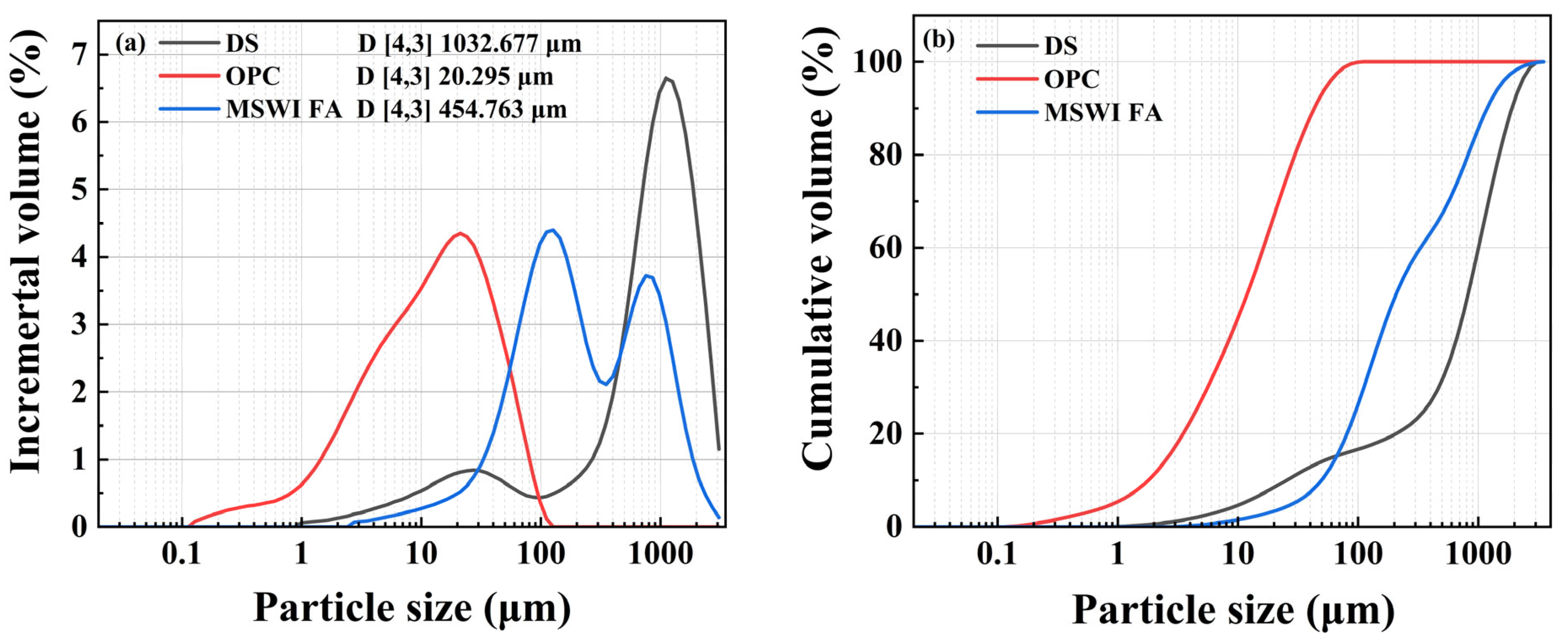
| DS | MSWI FA | ||
|---|---|---|---|
| Specific gravity | 2.09 | Specific gravity | 2.54 |
| Liquid limit (%) | 51.2 | Air-dry water content (%) | 26.34 |
| Plastic limit (%) | 30.3 | Saturated water content (%) | 52.63 |
| Plasticity index | 20.9 | Bulk density (g/cm3) | 1.01 |
| Natural water content (%) | 129 | Particle size (mm) | 0–5 |
| Thermophysical Propertiese | DS | MSWI FA | OPC |
|---|---|---|---|
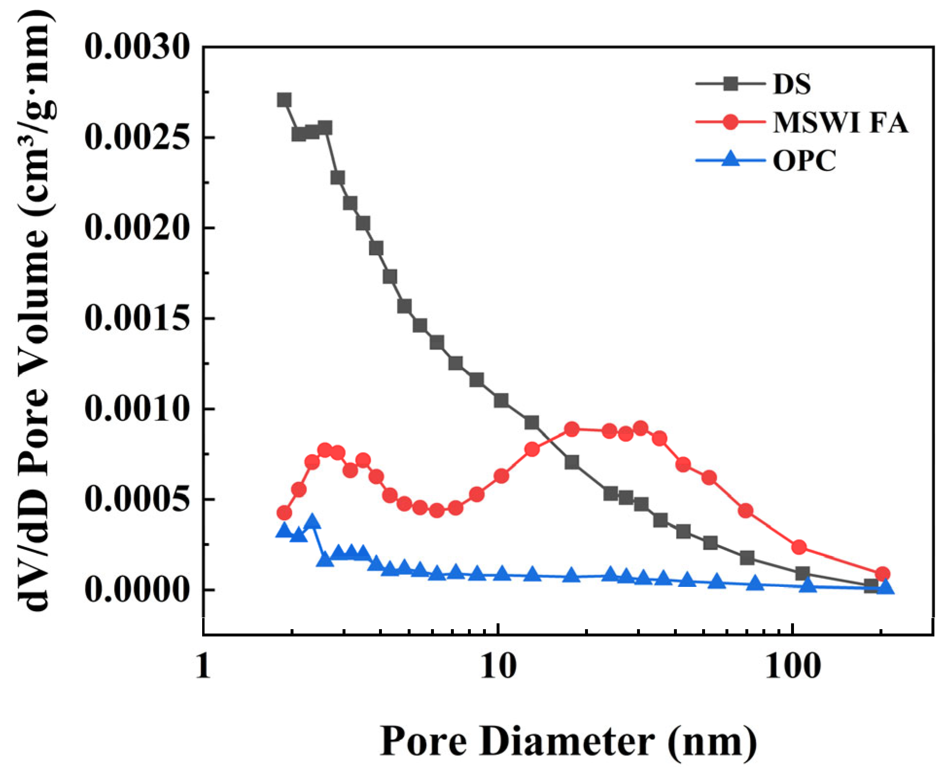
| BET Surface Area (m2/g) | 20.6539 | 18.0049 | 1.9086 |
| Micropore volume (cm3/g) | 0.001241 | 0.002790 | 0.000046 |
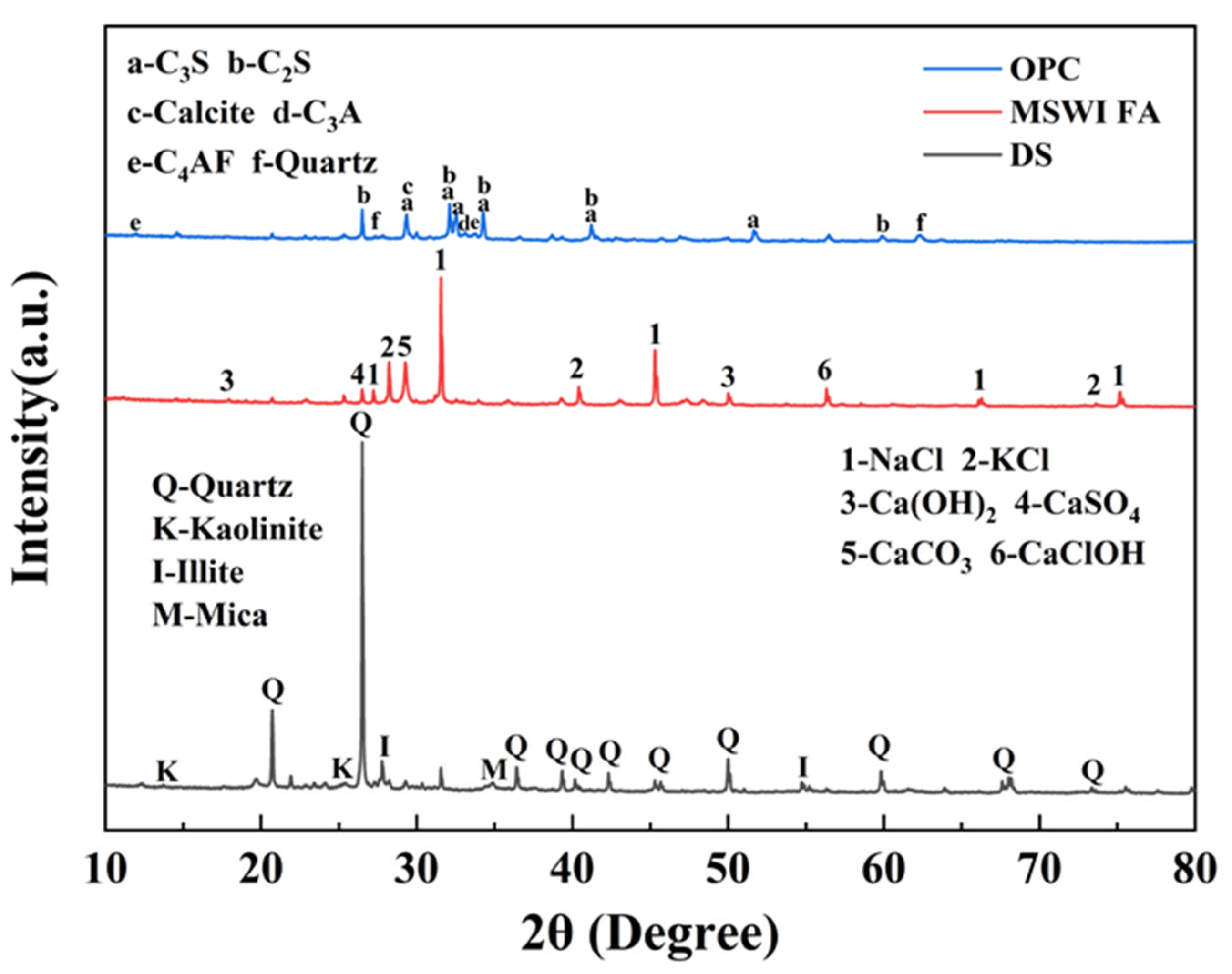
| Materials | SiO2 | Al2O3 | Fe2O3 | Na2O | K2O | MgO | CaO | SO3 | Cl | LOI |
|---|---|---|---|---|---|---|---|---|---|---|
| DS | 63.66 | 15.47 | 5.20 | 2.03 | 2.68 | 1.83 | 4.77 | 1.11 | 1.71 | 1.54 |
| MSWI FA | 2.84 | 0.87 | 0.65 | 17.76 | 7.55 | 1.66 | 35.93 | 6.14 | 24.78 | 1.82 |
| OPC | 23.07 | 6.66 | 5.31 | 0.37 | 1.01 | 3.33 | 55.03 | 3.84 | 0.12 | 1.26 |
| Number | OPC (g) | FA (g) | DS (g) | Ratio (PC:FA:DS) |
|---|---|---|---|---|
| C10F0 | 50 | 0 | 500 | 1:0:10 |
| C10F20 | 50 | 100 | 500 | 1:2:10 |
| C10F40 | 50 | 200 | 500 | 1:4:10 |
| C10F60 | 50 | 300 | 500 | 1:6:10 |
| C15F0 | 75 | 0 | 500 | 3:0:20 |
| C15F20 | 75 | 100 | 500 | 3:4:20 |
| C15F40 | 75 | 200 | 500 | 3:8:20 |
| C15F60 | 75 | 300 | 500 | 3:12:20 |
Disclaimer/Publisher’s Note: The statements, opinions and data contained in all publications are solely those of the individual author(s) and contributor(s) and not of MDPI and/or the editor(s). MDPI and/or the editor(s) disclaim responsibility for any injury to people or property resulting from any ideas, methods, instructions or products referred to in the content. |
© 2025 by the authors. Licensee MDPI, Basel, Switzerland. This article is an open access article distributed under the terms and conditions of the Creative Commons Attribution (CC BY) license (https://creativecommons.org/licenses/by/4.0/).
Share and Cite
Zhang, S.; Xu, H.; Shi, X.; Zhang, W.; Xu, J. Engineering Characteristics of Dredged Sediment Solidified by MSWI FA and Cement Under Different Curing Conditions. Materials 2025, 18, 2622. https://doi.org/10.3390/ma18112622
Zhang S, Xu H, Shi X, Zhang W, Xu J. Engineering Characteristics of Dredged Sediment Solidified by MSWI FA and Cement Under Different Curing Conditions. Materials. 2025; 18(11):2622. https://doi.org/10.3390/ma18112622
Chicago/Turabian StyleZhang, Shucheng, Haoqing Xu, Xinmiao Shi, Wenyang Zhang, and Jinyuan Xu. 2025. "Engineering Characteristics of Dredged Sediment Solidified by MSWI FA and Cement Under Different Curing Conditions" Materials 18, no. 11: 2622. https://doi.org/10.3390/ma18112622
APA StyleZhang, S., Xu, H., Shi, X., Zhang, W., & Xu, J. (2025). Engineering Characteristics of Dredged Sediment Solidified by MSWI FA and Cement Under Different Curing Conditions. Materials, 18(11), 2622. https://doi.org/10.3390/ma18112622