
Brazing of Thin-Walled Stainless Steel Using Environmentally Friendly Ni-Cr-P Electrodeposition: Degradation Mechanism of Brazed Joint and Corresponding Improvement Strategy

Abstract
1. Introduction
2. Materials and Methods
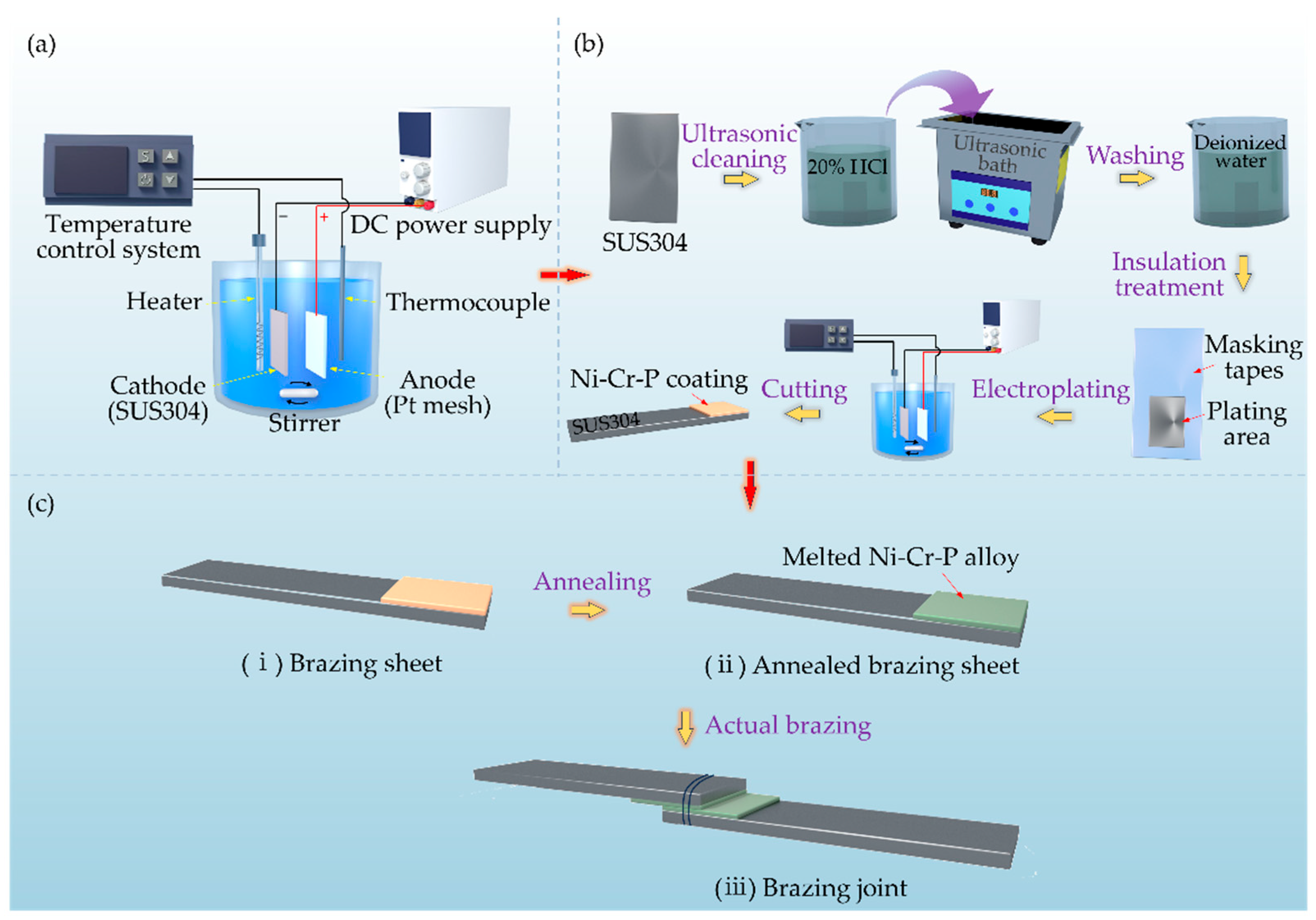
2.1. Electrodeposition of Ni-Cr-P Alloy Interlayers
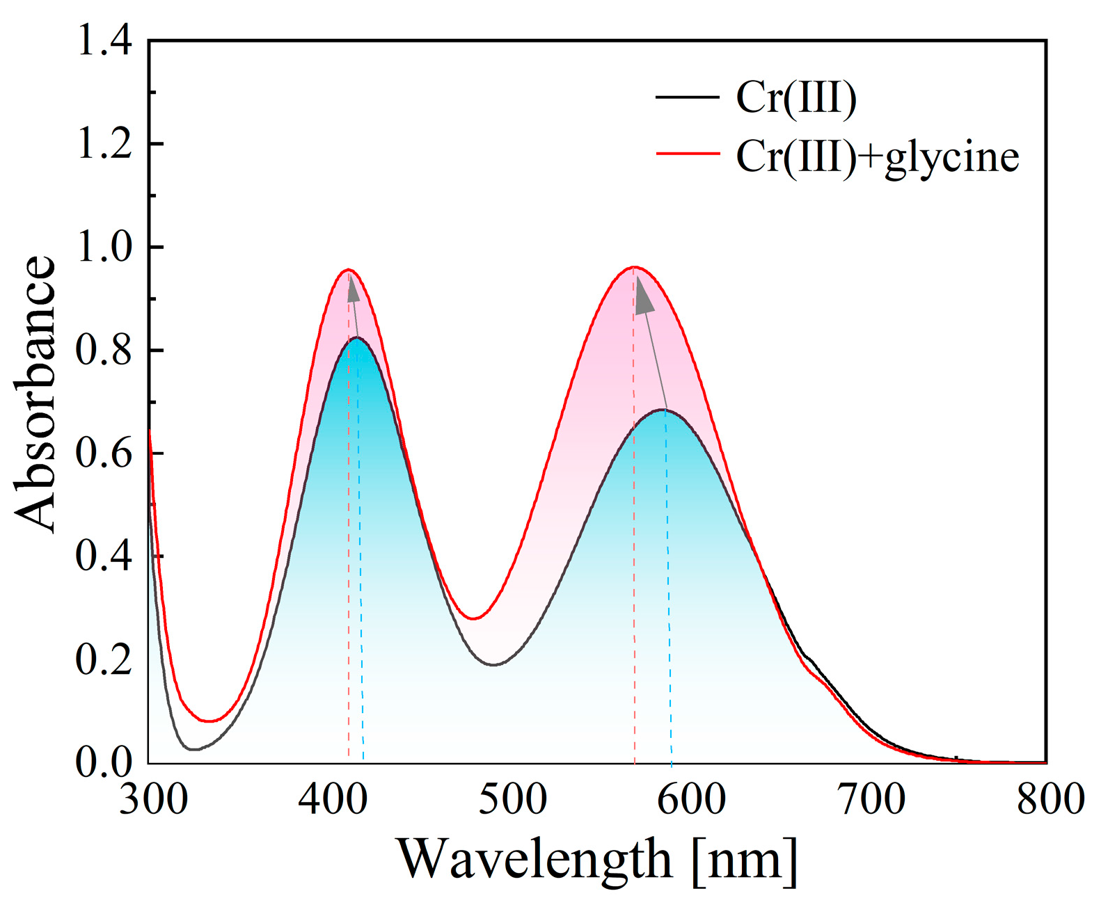
2.2. Identification of Electroactive Cr(III) Complexes
2.3. Materials and Brazing Tests
2.4. Microstructural Characterization
2.5. Shear Strength Properties
3. Results and Discussion
3.1. Electrodeposition of Ni-Cr-P Alloy
3.1.1. Identification of Electroactive Cr(III) Complex
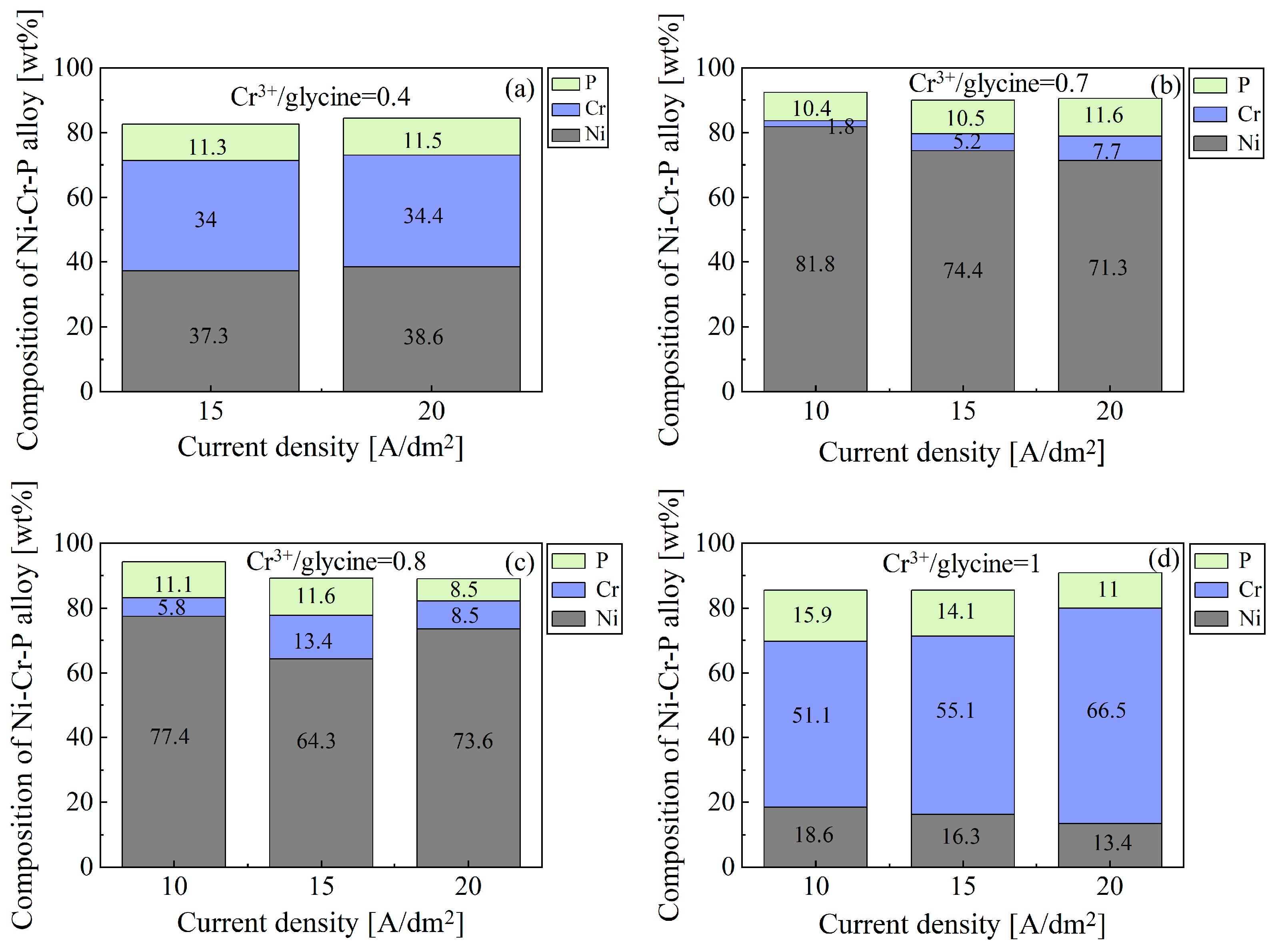
3.1.2. Chemical Composition and Surface Morphology of Electrodeposited Ni-Cr-P Alloy
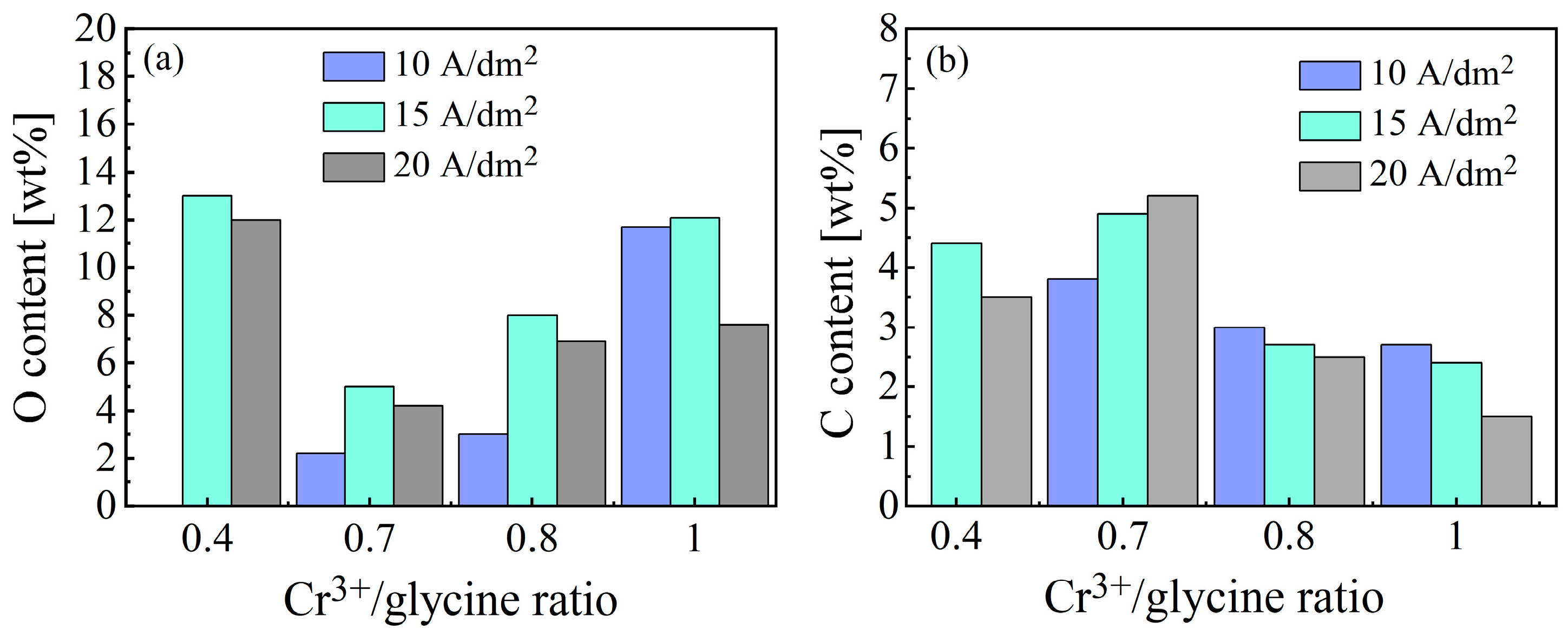
3.1.3. O and C Incorporation Behavior During Ni-Cr-P Electrodeposition
3.2. Formation of Brazed Joint
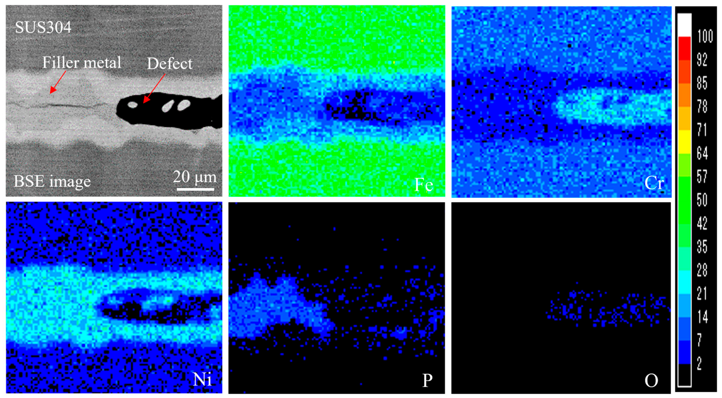
3.2.1. Effect of Impurities on Brazed Joint
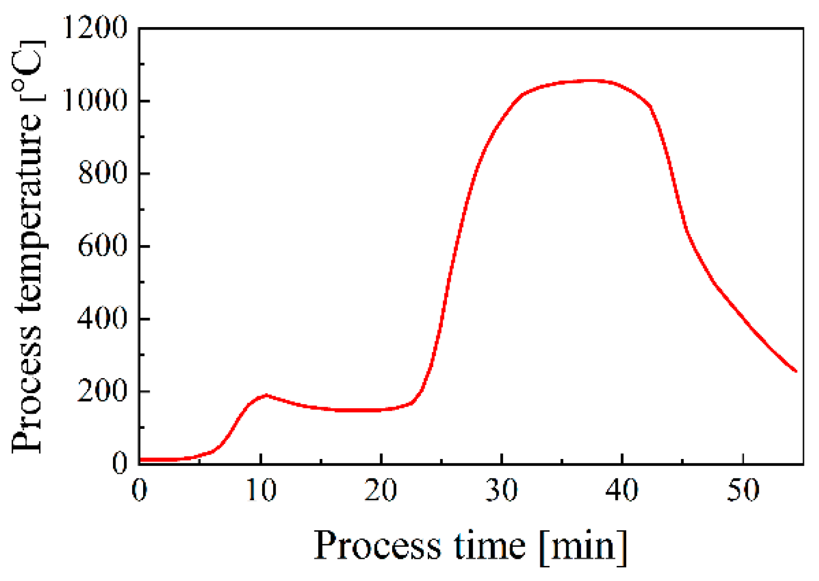
3.2.2. Effect of Preheating on Brazed Joint
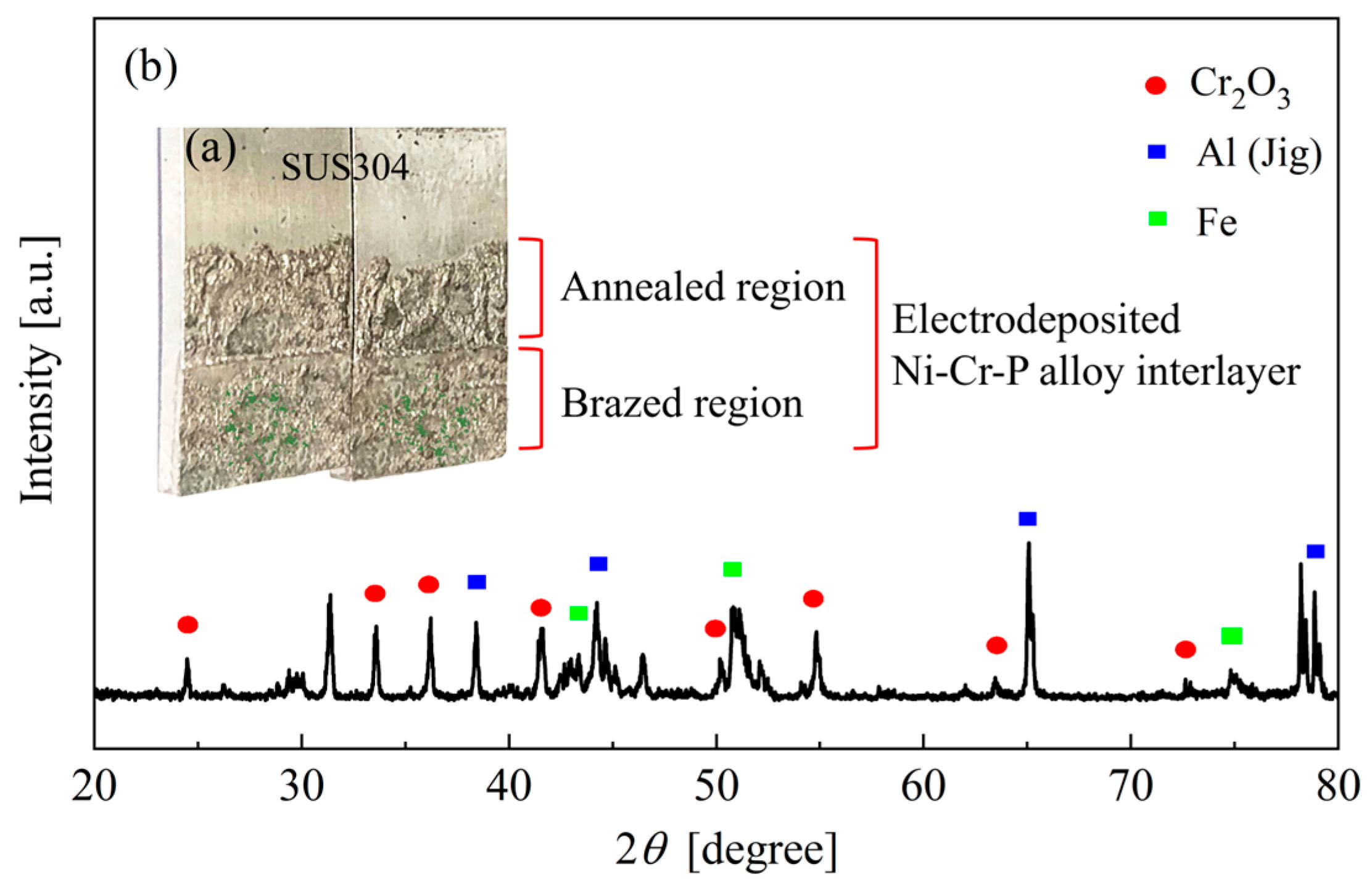
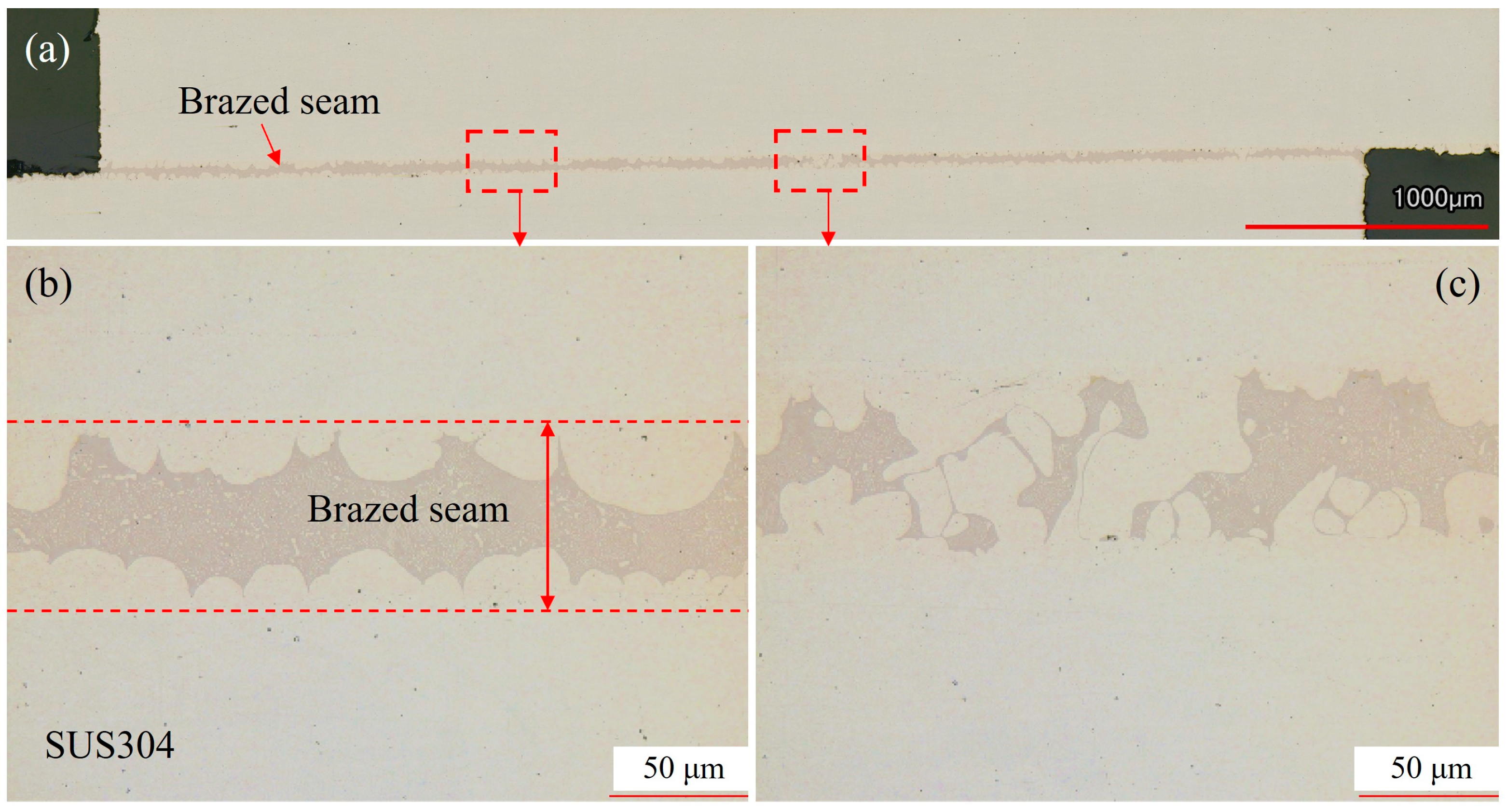
3.3. Microstructure Characterization
3.4. Strength Property of Brazed Joint
3.4.1. Shear Strength
3.4.2. Fracture Mode
4. Conclusions
Author Contributions
Funding
Institutional Review Board Statement
Informed Consent Statement
Data Availability Statement
Conflicts of Interest
References
- Zhang, L.; Long, W.; Zhong, S.; Pei, Y. Microstructures and properties of Ni-Cr-P filler metals and brazed joints bearing CNTs. Mater. Trans. 2022, 63, 1375–1379. [Google Scholar] [CrossRef]
- Zhang, H.; Zhu, W.; Zhang, T.; Guo, C.; Ran, X. Effect of brazing temperature on microstructure and mechanical property of high nitrogen austenitic stainless steel joints brazed with Ni-Cr-P filler. SIJ Int. 2019, 59, 300–304. [Google Scholar] [CrossRef]
- Li, G.; Zhang, P.; Shi, H.; Yu, Z. Microstructure and properties of Cr18-Ni8 steel joints brazed with BNi7+3%Cu composite solder. Vacuum 2018, 148, 303–311. [Google Scholar] [CrossRef]
- Liu, S.; Shohji, I.; Iioka, M.; Hashimoto, A.; Hirohashi, J.; Wake, T.; Arai, S. Micro-Brazing of Stainless Steel Using Ni-P Alloy Plating. Appl. Sci. 2019, 9, 1094. [Google Scholar] [CrossRef]
- Grazia Giuseppina, P.; Carlo, V.; Carlo, V.; Marco, C.; Federica, C.; Angela, F.; Giovanni, D.; Enzo, C. Physical investigation of electrophoretically deposited graphene oxide and reduced graphene oxide thin films. J. Appl. Phys. 2016, 120, 195307. [Google Scholar]
- Neumann, T.V.; Kara, B.; Sargolzaeiaval, Y.; Im, S.; Ma, J.; Yang, J.; Ozturk, M.C.; Dickey, M.D. Aerosol spray deposition of liquid metal and elastomer coatings for rapid processing of stretchable electronics. Micromachines 2021, 12, 146. [Google Scholar] [CrossRef]
- Tatiana, N.M.; Rajathsing, K.; Tatiana, S.M. Sol-gel materials for electrochemical applications: Recent advances. Coatings 2022, 12, 1625. [Google Scholar] [CrossRef]
- Okonkwo, B.O.; Jeong, C.; Jang, C. Advances on Cr and Ni Electrodeposition for Industrial Applications—A Review. Coatings 2022, 12, 1555. [Google Scholar] [CrossRef]
- Farzad, N. Electrodeposition of nanostructured materials. In Springer Seires in Surface Sciences; Roberto, C., Gerhard, E., Hans-Joachim, F., Hans, L., Mario Agostino, R., Eds.; Springer International Publishing: Cham, Switzerland, 2017; Volume 62, pp. 75–118. [Google Scholar]
- King, P.P.; McGeary, R.K. Braze bonding stainless-steel fuel elements for nuclear reactors. Weld. J. 1959, 38, 241–246. [Google Scholar]
- Liu, S.; Shohji, I.; Kobayashi, T.; Hirohashi, J.; Wake, T.; Yamamoto, H.; Kamakoshi, Y. Mechanistic study of Ni-Cr-P alloy electrodeposition and characterization of deposits. J. Electroanal. Chem. 2021, 897, 115582. [Google Scholar] [CrossRef]
- Maeda, A.; Sakamoto, Y.; Obayashi, S.; Kajikawa, S. Brazing Method, Brazement, Method of Production of Corrosion-Resistant Heat Exchanger, and Corrosion-Resistant Heat Exchanger. European Patent Application, U.S. Patent EP1153690A1, 5 May 2001. [Google Scholar]
- Tian, X.; Chen, S.; Zhu, F.; Cai, Z.; Wang, L. Toward cleaner production of trivalent chromium electrodeposition: Mechanism, process and challenges. J. Clean. Prod. 2024, 476, 143768. [Google Scholar] [CrossRef]
- Büker, L.; Böttcher, R.; Leimbach, M.; Hahne, T.; Dickbreder, R.; Bund, A. Influence of carboxylic acids on the performance of trivalent chromium electrolytes for the deposition of functional coatings. Electrochim. Acta 2022, 411, 140054. [Google Scholar] [CrossRef]
- Nobl, F.E.B.; Mahmoud, A.E.J.; Magdy, A.M.I. A novel environmentally friendly mixed complex bath for electrodeposition of a thin film of crack-free FeCrNi stainless steel-like. J. Appl. Electrochem. 2024, 54, 2757–2767. [Google Scholar]
- Dimitri Del, P.; Jérôme, F.; Christine, G.; Cyril, C.; Jean Charles, D.; Isabelle Le, H. Determination of the chromium (III) reduction mechanism during chromium electroplating. Electrochim. Acta 2018, 284, 234–241. [Google Scholar]
- Xu, L.; Pi, L.; Dou, Y.; Cui, Y.; Mao, X.; Lin, A.; Fernandez, C.; Peng, C. Electroplating of thick hard chromium coating from a trivalent chromium bath containing a ternary complexing agent: A methodological and mechanistic study. ACS Sustain. Chem. Eng. 2020, 8, 15540–15549. [Google Scholar] [CrossRef]
- Manoj, J.P.; Rama Srinivas, V.; da Cauê Corrêa, S.; Saba, S.; de Arnoud, V.; Andreas, E.; Michael, R. Chromium coatings from trivalent chromium plating baths: Characterization and cathodic delamination behaviour. Corros. Sci. 2021, 187, 109525. [Google Scholar]
- Wijenberg, J.H.O.J.; Steegh, M.; Aarnts, M.P.; Lammers, K.R.; Mol, J.M.C. Electrodeposition of mixed chromium metal-carbide-oxide coatings from a trivalent chromium-formate electrolyte without a buffering agent. Electrochim. Acta 2015, 173, 819–826. [Google Scholar] [CrossRef]
- Razaghi, Z.; Rezaei, M.; Tabaian, S.H. Electrochemical noise and impedance study on the corrosion of electroplated Ni-Cr coatings in HBF4 aqueous solution. J. Electroanal. Chem. 2020, 859, 113838. [Google Scholar] [CrossRef]
- Haque, M.E.; Hoque, M.A.; Islam, M.M.; Islam, M.S.; Mustafa, C.M. Effect of Various Operating Parameters on Trivalent Chromium Electroplating. J. Sci. Res. Rep. 2017, 13, 1–9. [Google Scholar] [CrossRef]
- Dennys Fernandez, C.; German Orozco, G.; Julieta Torres, G. Study on the electrodeposition of chromium from Cr(III) solution in the presence of oxalate and acetate anions. Int. J. Electrochm. Sci. 2020, 15, 5741–5757. [Google Scholar]
- Mcdougall, J.; El-sharif, M.; Ma, S. Chromium electrodeposition using a chromium(III) glycine complex. J. Appl. Electrochem. 1998, 28, 929–934. [Google Scholar] [CrossRef]
- Enrico, B.; Cristina, V.M.; Eva, P.; Jordi, S.; Robert, M.U.; Stefano, M.; Johann, M.; Laetitia, P. ‘Green’ Cr(III)–glycine electrolyte for the production of FeCrNi coatings: Electrodeposition mechanisms and role of by-products in terms of coating composition and microstructure. RSC Adv. 2019, 9, 25762. [Google Scholar]
- Matsu, K. Brazing of Ni based brazing filler metals and the latest trend. Weld. Technol. 2011, 59, 54–57. [Google Scholar]
- Mandich, N.V. Chemistry & Theory of chromium deposition: Part I -chemistry. Plat. Surf. Finish. 1997, 84, 108–115. [Google Scholar]
- Korshunov, V.N.; Safonov, V.A.; Vykhodtseva, L.N. Structural features of the electrode/solution interface at the reduction of Cr3+(aq) cations on liquid mercury and solid indium electrodes in acidic media. Russ. J. Electrochem. 2008, 44, 255–264. [Google Scholar] [CrossRef]
- Zeng, Z.; Zhang, Y.; Zhao, W.; Zhang, J. Role of complexing ligands in trivalent chromium electrodeposition. Surf. Coat. Technol. 2011, 205, 4771–4775. [Google Scholar] [CrossRef]
- Li, B.; Lin, A.; Wu, X.; Zhang, Y.; Gan, F. Electrodeposition and characterization of Fe-Cr-P amorphous alloys from trivalent chromium sulfate electrolyte. J. Alloys Compd. 2008, 453, 93–101. [Google Scholar] [CrossRef]
- Marangoni, D.G.; Smith, R.S.; Roscoe, S.G. Surface electrochemistry of the oxidation of glycine at Pt. Can. J. Chem. 1989, 67, 921–926. [Google Scholar] [CrossRef]
- Madoka, H.; Songhak, Y.; Gaylord, G.; Zhang, Y.; Cédric, F.; Christoph, N.; Anke, W.; Johann, M.; Laetitia, P. The electrodeposition of FeCrNi stainless steel: Microstructural changes induced by anode reactions. Phys. Chem. Chem. Phys. 2014, 16, 26375–26384. [Google Scholar]
- Pramod Kumar, U.; Joseph Kennady, C. Characterization of chromium electrodeposits obtained from trivalent electrolytes containing formaldehyde as additive. Int. J. Thin Fil. Sci. Tec. 2015, 4, 14–153. [Google Scholar]
- Shi, H.; Yu, Z.; Cho, J.R. A study on the microstructure and properties of brazing joint for Cr18-Ni8 steel using a BNi7+9%Cu mixed filler metal. Vacuum 2018, 151, 226–232. [Google Scholar] [CrossRef]
- Wu, N.; Li, Y.; Wang, J.; Puchkov, U.A. Vacuum brazing of super-Ni/NiCr laminated composite to Cr18-Ni8 steel with NiCrP filler metal. J. Mater. Process Technol. 2012, 212, 794–800. [Google Scholar] [CrossRef]
- Wang, J.; Wang, J.; Li, Y.; Zheng, D. Microstructure and shear strength in brazing joint of Mo-Cr composite with 304 stainless steel by Ni-Cr-P filler metal. High. Temp. Mater. Proc. 2015, 34, 347–351. [Google Scholar] [CrossRef]


| Composition | Concentration (M) | Electrodeposition Conditions | |||
|---|---|---|---|---|---|
| S1 | S2 | S3 | S4 | ||
| CrCl3·6H2O | 0.4 | 0.35 | 0.4 | 0.5 | Current density: 10, 15, 20 A/dm2 pH: 1.8 Bath temperature: 30 °C Plating time: 70–150 min Anode: Pt mesh Cathode: SUS304/Cu Electrode distance: 2.5 cm |
| NiCl2·6H2O | 0.25 | 0.3 | 0.25 | 0.126 | |
| NaH2PO2·H2O | 0.14 | 0.14 | 0.14 | 0.24 | |
| C2H5NO2 (Glycine) | 1.0 | 0.5 | 0.5 | 0.5 | |
| C6H5Na3O7 | 0.2 | 0.2 | 0.2 | - | |
| NH4Cl | 0.5 | 0.5 | 0.5 | 0.5 | |
| NaBr | 0.145 | 0.145 | 0.145 | 0.145 | |
| NaCl | 0.5 | 0.5 | 0.5 | 0.5 | |
| H3BO3 | 0.5 | 0.5 | 0.5 | 0.5 | |
| C7H4NO3SNa·2H2O | 0.6 g/L | 0.6 g/L | 0.6 g/L | 0.6 g/L | |
| SDS | 0.1 g/L | 0.1 g/L | 0.1 g/L | 0.1 g/L | |
| Composition | Concentration (M) | |
|---|---|---|
| Cr | Cr + Glycine | |
| CrCl3·6H2O | 0.4 | 0.4 |
| NiCl2·6H2O | - | - |
| C2H5NO2 (Glycine) | - | 0.5 |
| NH4Cl | 0.5 | 0.5 |
| NaBr | 0.145 | 0.145 |
| NaCl | 0.5 | 0.5 |
| H3BO3 | 0.5 | 0.5 |
| C7H4NO3SNa·2H2O | 0.6 g/L | 0.6 g/L |
| SDS | 0.1 g/L | 0.1 g/L |
| Symbol | Ni | Cr | P | S | Si | Mn | C | O | Fe |
|---|---|---|---|---|---|---|---|---|---|
| SUS304 | 8.00–10.50 | 18.00–20.00 | ≤0.045 | ≤0.03 | ≤1.00 | ≤2.00 | ≤0.08 | - | Bal. |
| Ni-Cr-P | Bal. | 6.00 | 11.10 | - | - | - | 2.80 | 2.70 | - |
| Ni (Mass%) | Cr (Mass%) | P (Mass%) | O (Mass%) | C (Mass%) | Cu (Mass%) | |
|---|---|---|---|---|---|---|
| Ni-P | 81.9 | - | 12.2 | 1.2 | - | 4.7 |
| Ni-Cr-P | 21.4 | 15.1 | 7.6 | 14.7 | 2.2 | 39 |
| Points | Element Composition (mol%) | Possible Phase | |||
|---|---|---|---|---|---|
| Ni | Cr | P | Fe | ||
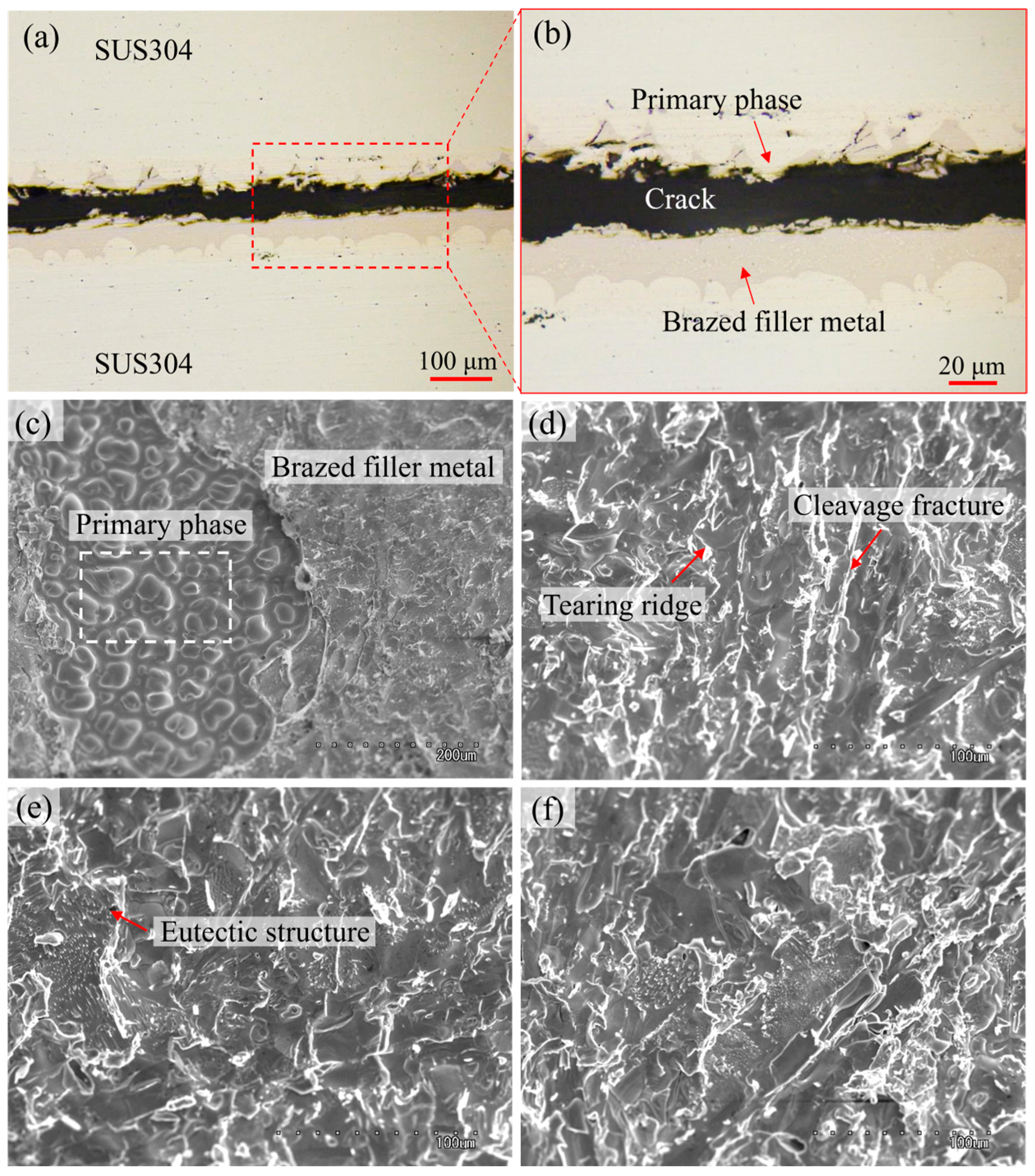
| 1 | 82.05 | 7.47 | 1.51 | 8.98 | Ni-Fe-Cr solid solution |
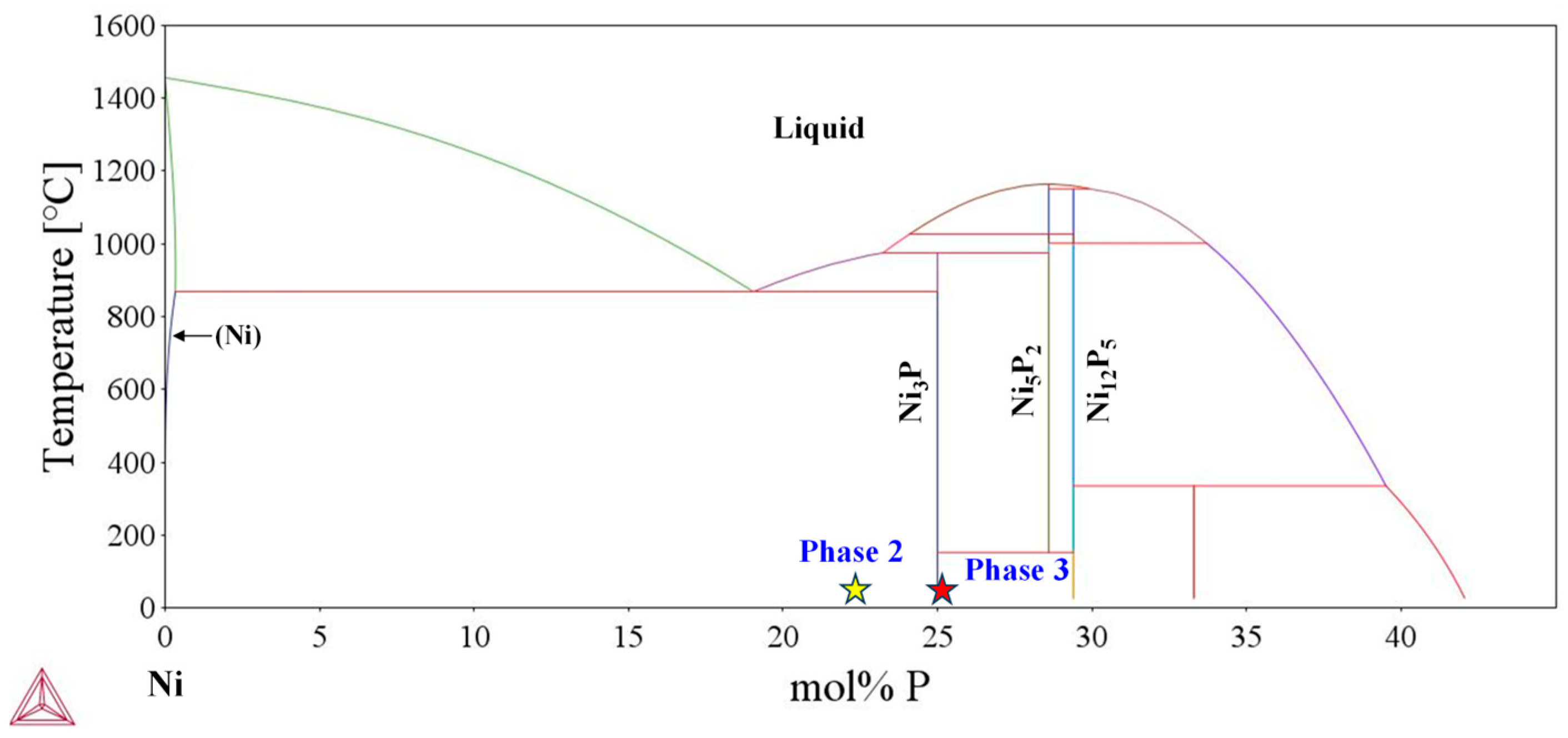
| 2 | 69.64 | 4.21 | 22.68 | 3.48 | Ni3P eutectic phase |
| 3 | 68.16 | 3.42 | 25.35 | 3.07 | (Ni3P + little Ni5P2) eutectic phase |
| Ref. | Base Metal | Interlayer Thickness (μm) | Temperature (°C) | Time (min) | Shear Strength (MPa) |
|---|---|---|---|---|---|
| This work | SUS304 | Ni-Cr-P (20) | 1020 | 20 | 63 |
| [2] | HNS | Ni-Cr-P (50) | 950, 1000, 1050 | 20 | 60–163 |
| [3] | SUS304 | Ni-Cr-P + 3%Cu (30, 100) | 940, 960, 980 | 5, 30 | 84–119 |
| [34] | Super-Ni/NiCr laminated composite/SUS304 | Ni-Cr-P (-) | 940, 980, 1040 | 20 | 36–137 |
| [35] | SUS304/Mo-Cu composite | Ni-Cr-P (30) | 980 | 20 | 155 |
Disclaimer/Publisher’s Note: The statements, opinions and data contained in all publications are solely those of the individual author(s) and contributor(s) and not of MDPI and/or the editor(s). MDPI and/or the editor(s) disclaim responsibility for any injury to people or property resulting from any ideas, methods, instructions or products referred to in the content. |
© 2025 by the authors. Licensee MDPI, Basel, Switzerland. This article is an open access article distributed under the terms and conditions of the Creative Commons Attribution (CC BY) license (https://creativecommons.org/licenses/by/4.0/).
Share and Cite
Liu, S.; Luan, Y.; Shohji, I. Brazing of Thin-Walled Stainless Steel Using Environmentally Friendly Ni-Cr-P Electrodeposition: Degradation Mechanism of Brazed Joint and Corresponding Improvement Strategy. Materials 2025, 18, 2406. https://doi.org/10.3390/ma18102406
Liu S, Luan Y, Shohji I. Brazing of Thin-Walled Stainless Steel Using Environmentally Friendly Ni-Cr-P Electrodeposition: Degradation Mechanism of Brazed Joint and Corresponding Improvement Strategy. Materials. 2025; 18(10):2406. https://doi.org/10.3390/ma18102406
Chicago/Turabian StyleLiu, Shubin, Yuqi Luan, and Ikuo Shohji. 2025. "Brazing of Thin-Walled Stainless Steel Using Environmentally Friendly Ni-Cr-P Electrodeposition: Degradation Mechanism of Brazed Joint and Corresponding Improvement Strategy" Materials 18, no. 10: 2406. https://doi.org/10.3390/ma18102406
APA StyleLiu, S., Luan, Y., & Shohji, I. (2025). Brazing of Thin-Walled Stainless Steel Using Environmentally Friendly Ni-Cr-P Electrodeposition: Degradation Mechanism of Brazed Joint and Corresponding Improvement Strategy. Materials, 18(10), 2406. https://doi.org/10.3390/ma18102406