1. Introduction
The rapid increase in global energy consumption has led to a strong dependence on fossil fuels, further exacerbating environmental issues such as climate change, air pollution, and ecosystem degradation [
1,
2]. As energy demand continues to rise, the urgency to diversify the energy matrix and invest in renewable sources becomes even more critical. However, many traditional solutions, such as large hydroelectric plants, require expensive infrastructure and can have negative environmental impacts, including the disruption of aquatic ecosystems and the displacement of communities [
3,
4]. In this scenario, it is essential to develop more accessible and sustainable technologies that allow for the efficient use of natural resources while minimizing ecological impact. Additionally, addressing these challenges requires innovative policies, improved energy storage solutions, and decentralized renewable energy systems to ensure a more resilient and environmentally friendly energy future.
Gravitational vortex turbines represent an alternative in the field of hydrokinetic energy generation, as they enable the transformation of water energy into electricity without the need for dams or reservoirs [
5,
6]. These turbines operate by creating a vortex within a circulation and discharge chamber, harnessing the kinetic energy of the water flow to drive a rotor connected to a generator. Their compact design and ability to function with low water flow rates make them an ideal solution for rural communities or regions with limited water resources. The power generation system consists of an inlet channel, a circulation chamber, a discharge chamber, the rotor, the electric generator, and the regulation and control system [
7].
Despite advancements in the design and optimization of gravitational vortex turbines, most current studies have focused on improving their hydrodynamic and mechanical performance through both numerical and experimental research [
8,
9,
10,
11]. However, these developments have primarily relied on conventional materials such as metals and synthetic polymers, due to their favorable mechanical properties and compatibility with existing manufacturing processes. In laboratory-scale models, the use of 3D printing filaments and recycled polymers has been reported, which not only facilitates the fabrication of complex geometries with high precision but also promotes a more sustainable approach. In practical applications, steel and concrete structures have been employed, where steel allows for faster construction and greater recyclability, while reinforced concrete, though more cost-effective, requires extended curing times [
5,
12,
13].
To date, only one study has been identified that combines fique natural fibers with gravitational vortex turbines. The authors of [
14] evaluated a biocomposite material made from unsaturated polyester resin reinforced with fique fiber as a sustainable and cost-effective alternative for constructing rotor blades of a gravitational vortex turbine. Using the manual impregnation method, laminates with three layers of fique fiber were produced, yielding a lightweight material with promising mechanical properties. Compared to conventional materials like aluminum and stainless steel, the biocomposite demonstrated lower density and environmental advantages. Mechanical tests (tensile and bending) confirmed its suitability, and a functional rotor prototype was successfully manufactured, highlighting the biocomposite’s potential for application in hydrokinetic systems.
The use of materials such as biopolymers or natural fiber-reinforced composites presents a significant opportunity to reduce environmental impact and enhance the functionality of these systems. Integrating these materials into the development of gravitational vortex turbines could optimize their energy efficiency throughout their entire lifecycle, from production to end-of-life disposal. This opens new avenues for research in the field of sustainable materials, enabling the creation of more efficient and environmentally responsible technologies for renewable energy generation. Furthermore, the implementation of natural materials in the fabrication of turbine rotors could minimize their environmental footprint and promote the use of local resources, thereby contributing to a more sustainable and accessible energy transition. However, their implementation faces critical challenges, including inferior mechanical properties, susceptibility to moisture, complex manufacturing processes, and difficulties in achieving optimal dynamic balance. Additionally, the variability in the properties of natural materials and their potentially higher costs may limit their scalability and competitiveness. Overcoming these obstacles requires advances in material treatment, optimization of manufacturing processes, and the development of strategies for sustainable end-of-life management.
The manufacturing of rotors for gravitational vortex turbines using biopolymers and natural fibers can be approached through various processes, each with its own advantages and challenges. Three-dimensional printing stands out for its high precision and ability to create complex geometries, reducing material waste [
15,
16]; however, it may be limited by the mechanical strength of biopolymers and the costs associated with large-scale production. This process can be enhanced by incorporating natural fibers, such as fique, hemp, or flax, into biopolymer matrices like polylactic acid (PLA), enabling the creation of sustainable and customized components. Despite its potential, challenges such as the lower mechanical strength of natural fibers, the need to adjust printing parameters to avoid thermal degradation, and the higher costs of producing composite filaments must be addressed. On the other hand, compression molding is a scalable and efficient option for natural fiber-reinforced composites, although it requires high-precision molds that can increase initial costs and pose challenges in achieving optimal dynamic balance. Injection molding offers high repeatability and precision, making it ideal for uniform geometries, but it is restricted to materials with suitable flow properties and involves high equipment and mold costs. The manual molding process provides flexibility in using different fibers and resins, being low-cost for prototypes, but its precision and consistency are lower, which can result in dynamic imbalances. A hybrid approach, combining techniques such as 3D printing for critical parts and compression molding for final assembly, leverages the strengths of multiple processes, though it increases complexity and costs. Finally, post-manufacturing treatments, such as precision machining or the application of coatings, improve rotor quality and durability but add time and production costs. Overall, the choice of process will depend on factors such as production volume, required material properties, and available resources, making it crucial to explore innovative approaches that maximize the performance and sustainability of these materials. Integrating natural fibers into advanced manufacturing processes like 3D printing not only enhances sustainability but also opens new possibilities for creating efficient and eco-friendly energy systems.
This study presents the experimental characterization of a rotor for a gravitational vortex turbine fabricated using natural fibers, aiming to evaluate its performance and viability as an eco-friendly alternative for electric power generation. The importance and novelty of this article lie in the use of natural fibers as a manufacturing material, as the rotor design has already been validated previously. Key parameters such as system efficiency, structural resistance of the materials, and flow behavior are analyzed to assess its potential for applications in resource-limited areas. Additionally, the performance of the natural fiber rotor is compared to that of a 3D-printed rotor made from PLA, a biodegradable thermoplastic, providing insights into the advantages and limitations of each material in terms of energy generation and sustainability.
2. Materials and Methods
2.1. Importance of Natural Fibers in the Manufacturing of Turbine Rotors
The use of natural fibers in the manufacturing of hydro turbine rotors represents a significant step toward more sustainable energy solutions. Unlike synthetic materials such as fiberglass or carbon fiber, natural fibers such as flax, hemp, or jute are biodegradable, renewable, and have a lower carbon footprint. Their production requires less energy and generates fewer emissions, contributing to a more environmentally friendly manufacturing process. In addition, natural fiber composites offer a favorable strength-to-weight ratio, making them a competitive alternative for the reinforcement of modern composite materials [
17]. Compared to synthetic fibers and fiberglass, they overcome various limitations by offering improved mechanical, thermal, and physical properties, which can enhance turbine efficiency while reducing mechanical stress on other components [
18].
Furthermore, by minimizing reliance on petroleum-based materials, the adoption of natural fibers helps reduce environmental pollution and long-term waste accumulation. From a socio-economic perspective, incorporating locally sourced natural fibers supports rural economies and promotes sustainable agricultural practices, creating a circular economy model. Furthermore, these materials typically require fewer harmful chemicals during processing, lowering health risks for workers and reducing pollution in aquatic ecosystems. By integrating natural fibers into hydro turbine rotors, it is possible to achieve an optimal balance between performance, durability, and environmental responsibility, paving the way for more sustainable hydrokinetic energy systems.
A clear example of their implementation is the development of wind turbine blades made from composites based on sisal fibers, which not only reduces the carbon footprint of their production but also facilitates their recycling at the end of their useful life. Similarly, the automotive industry has begun to integrate natural fibers into the manufacture of structural components and interior panels, achieving lighter and more energy-efficient vehicles [
19].
According to Amzil et al., the integration of hemp fibers into the manufacture of wind turbine blades has shown significant economic and environmental advantages, while maintaining established design requirements. These findings highlight their potential as a viable alternative to traditional glass fiber-reinforced composite materials. The studies indicate that this modification allowed for a reduction in both density and cost compared to a reference model composed exclusively of glass fiber and epoxy resin [
20].
The study conducted by Rua et al. investigated the use of fique fibers as reinforcement in a composite material with epoxy resin, allowing for exploring new limits in the dynamic behavior of these materials. The results indicated that the composite material had lower stiffness compared to pure epoxy resin; but, at the same time, it showed better performance under stress conditions. In addition, its fracture was not brittle, evidencing greater flexibility and a better response to deformation under dynamic loading. Its impact resistance under static loading conditions was also highlighted [
21].
In Colombia, the fique industry is widely recognized, with an annual production close to 30,000 tons, making this fiber an attractive alternative for the development of new composite materials. The viability and application of these composites depend largely on economic factors, where weight reduction, cost reduction, and the availability of sustainable raw materials play a key role. Based on these findings, fique fiber was selected as a reinforcing material in this research.
For the matrix, a polyester resin from the Poliescol brand was used. It is thermosetting with a density of 1.15 g/mL, has gel time of 6 to 9 min, has a viscous pink appearance, and the recommended hardener is methyl ethyl ketone peroxide (MEK peroxide) mixed with 1% by weight. The polyester resin has an elasticity modulus of 3.6 GPa, a tensile strength of 45 Mpa, and an elongation of 2.4%. The fique fiber, also called Furcraea Andina, is an endemic species native to the South American Andes, which has an asymmetric 0/90° braiding configuration, with double fiber in the warp direction. The fique has a modulus of 8.2 to 9.1 GPa, a tensile strength of 132.4 Mpa, and an elongation of 9.8%. This fiber was analyzed using various characterization techniques to evaluate its morphology, chemical structure, and thermal properties. Morphological analysis by scanning electron microscopy (SEM) reveals that fique fibers have a compact surface, without fibrillation, and are separated by approximately 10 µm. They present roughness, typical of raw natural fibers, with some impurities and waxy material. In its cross-section, cell walls formed by microfibrils and a central lumen are observed, with a wall thickness between 1 and 10 µm and a lumen diameter of 0.1 to 20 µm. Fique reflects an irregular and fibrous structure characteristic of natural fibers. In the analysis of fique fiber by Fourier Transform Infrared Spectroscopy (FTIR), the presence of hydroxyl groups, C-H in cellulose and hemicellulose, was observed. In addition, carbonyl groups (C=O) and lignin (C=C) confirmed the lignocellulosic composition of the fiber [
22].
The characterization of the fique fiber composite with a polyester resin matrix focused on the interaction between the fiber and the polymeric matrix, evaluating its mechanical, thermal, and interface behavior. The morphological analysis of the fiber–matrix interface by SEM observed the interface between the fiber and the polyester resin. The fiber, with its rough surface and compact structure, shows a good interaction with the resin, which translates into greater compatibility and anchoring between both components. The resin seems to effectively impregnate the fique fibers, taking advantage of the surface roughness for better adhesion. In the mechanical properties, the results indicate that the composite presents an improvement in mechanical resistance compared to natural fibers without a matrix, thanks to the reinforcement provided by the polyester resin. The thermogravimetric analysis of the composites showed that the presence of polyester resin affects the thermal behavior of the material. The resin contributes to the thermal stabilization of the composite, although it may slightly alter the degradation temperature range compared to pure fique fibers. This type of composite, which combines natural fibers with polymeric matrices, presents a promising path towards sustainability in engineering materials, especially in industries seeking green solutions without compromising mechanical performance.
2.2. Geometry of the Gravitational Vortex Turbine Rotor
Gravitational vortex turbines are devices designed for hydrokinetic energy conversion through the generation of a stable vortex within a basin or vortex chamber. Their operating principle is based on inducing a rotational flow of water inside a cylindrical or conical tank, allowing the transformation of the fluid’s kinetic energy into mechanical energy via a rotor [
23]. Water enters the vortex chamber through a tangential inlet, generating rotational movement within the fluid. The basin’s geometry influences the formation of a downward helical flow, characteristic of the gravitational vortex. A rotor, positioned at the center of this vortex, is driven by the motion of the water. The captured mechanical energy is transferred to an electric generator, enabling its conversion into usable power. These turbines exhibit high efficiency in low-flow and low-head environments, making them suitable for renewable energy generation in rivers and water bodies with limited hydraulic conditions [
10].
The efficiency of gravitational vortex turbines is typically calculated by comparing the mechanical power output of the turbine (
) to the hydraulic power available in the flowing water (
P). The hydraulic power is determined using the equation
, where
is the density of water,
g is the acceleration due to gravity,
Q is the volumetric flow rate, and
H is the net head. The mechanical power output is usually obtained from measurements of torque (
T) and rotational speed (
). The overall efficiency (
) is then calculated using Equation (
1) [
8,
10]:
Figure 1 presents the turbine under study, designed for efficient energy conversion from the gravitational vortex. The rotor, optimized by Velásquez et al. [
8], features an advanced geometry that enhances performance by maximizing momentum transfer and minimizing energy losses. The curved blade configuration contributes to vortex stability, reinforcing its structure and optimizing turbine efficiency. Additionally, the blades are strategically inclined toward the rotor’s center, promoting vortex concentration in the central region, which enhances fluid interaction and improves energy conversion.
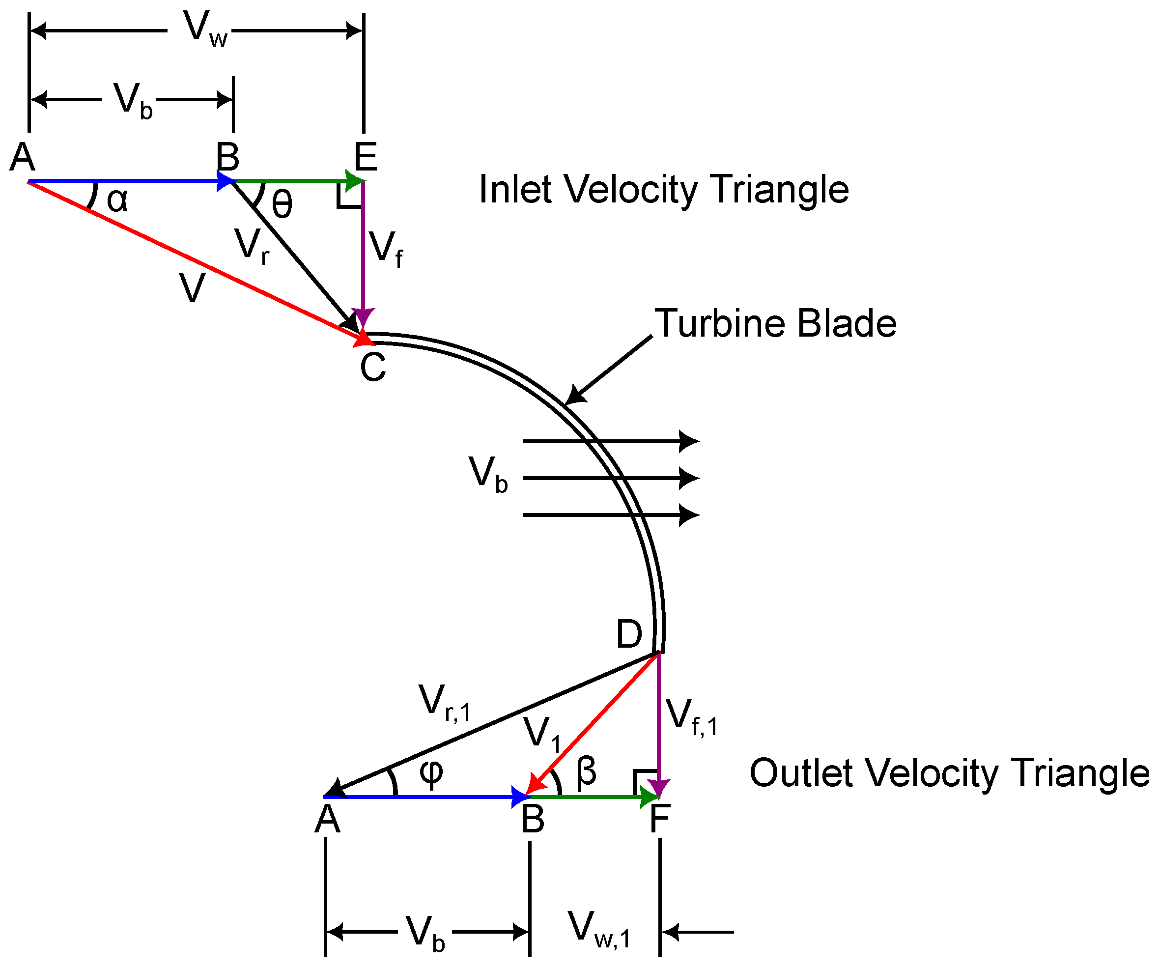
The rotor design incorporates specific inlet and outlet angles that govern fluid interaction with the blades, directly influencing velocity and momentum transfer—see
Figure 2. The blade inlet angle (
) is set at 16°, allowing water to enter smoothly while maintaining vortex stability, while the blade outlet angle (
) is 90°, ensuring an efficient redirection of flow. Similarly, the absolute velocity inlet angle (
) is 40°, and the absolute velocity outlet angle (
) is 43.8°, optimizing hydrodynamic performance by minimizing energy dissipation and improving momentum transfer to the rotor. The relative velocity twist angle (
) of 68.8° further enhances fluid guidance along the blade surface, contributing to a stable and efficient flow pattern.
Additionally, the rotor has a blade height (
L) of 200 mm, a diameter of 292 mm, and consists of six blades, each with a thickness of 3 mm. These blades are joined to a central shaft with a diameter of 19.5 mm.
Figure 3 and
Table 1 present the main dimensions of the rotor under study. These geometric parameters influence vortex formation and the effective interaction between the fluid and the rotor, ensuring a balance between sustaining a strong vortex structure and maximizing energy extraction.
2.3. Manufacturing Process of Turbine Rotors Using 3D Printing
The manufacturing process of turbine rotors using 3D printing begins with the creation of a digital 3D model using computer-aided design (CAD) software Autodesk Inventor professional 2025, where the rotor’s geometry is optimized to meet performance criteria such as flow efficiency, strength, and durability. Once the design is finalized, an appropriate material is chosen for 3D printing, which may include thermoplastics, metal alloys, or composite filaments depending on the desired properties of the rotor, such as flexibility, strength, or resistance to corrosion. Using additive manufacturing, the rotor is then fabricated layer by layer, with the printer extruding or melting the chosen material through a nozzle to build the rotor’s structure from the bottom up. This method offers precise control over the geometry of the rotor, allowing for complex and detailed shapes that would be challenging to achieve through traditional manufacturing techniques [
24,
25].
After printing, the rotor typically undergoes post-processing to enhance its surface finish and mechanical properties, including the removal of support structures, sanding, polishing, and curing the material for maximum strength. In the case of metal 3D printing, additional heat treatment may be used. Once the rotor is completed, it is assembled with other turbine components and tested under controlled conditions to assess its performance, mechanical strength, and efficiency. Based on the results, adjustments can be made to the design or manufacturing process to optimize the rotor’s performance, durability, and functionality. This process of 3D printing turbine rotors offers several advantages, such as reduced material waste, faster production times, and the ability to create highly customized and efficient designs for hydrokinetic and wind energy systems. The printing strategy of the rotor was first a 3D modeling in CAD software (Autodesk Inventor software 2025e) and then exported in STL format. PrusaSlicer was used to generate the G-code, optimizing printing parameters. The printing method was fused deposition molding (FDM), which is the standard technology in Ender 3 printers (Creality, Shenzhen, China). This method allows the rotor to be manufactured layer by layer, achieving a functional structure for initial tests. The rotor was printed using a PEGASUS Lite 3D printer (Creality, Shenzhen, China), which features a build volume of 300 × 300 × 300 mm. PLA was used for printing, with printing parameters with layer height 0.2 mm (for a balance between precision and printing time), 100% infill, printing speed 60 mm/s, extruder temperature 210 °C, bed temperature 60 °C (to improve adhesion), and support on the base.
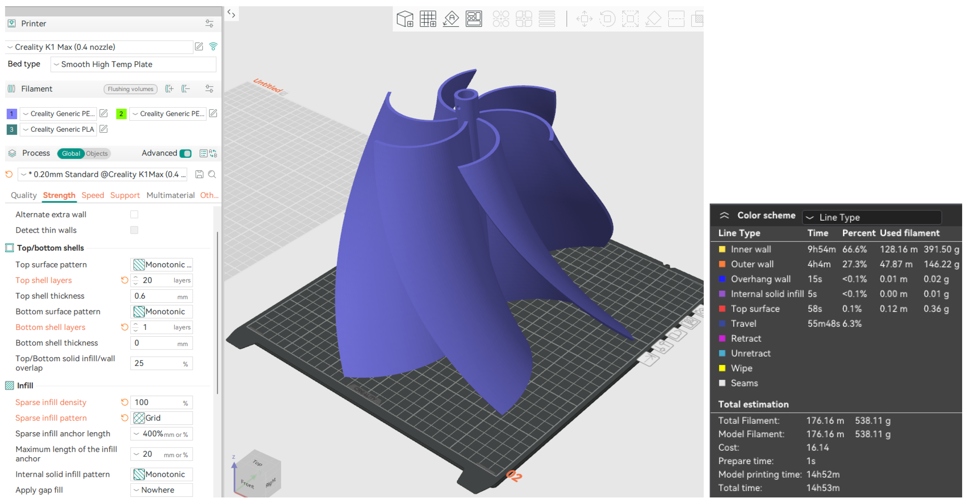
Figure 2 presents the printing parameters used in the software, as well as the total printing time and the amount of filament consumed. The total printing time was 14 h and 52 min, with 176.16 m of filament consumed, equivalent to 538.11 g. The printing parameters are presented in
Figure 4.
2.4. Manufacturing Process of Natural Fiber Turbine Rotor
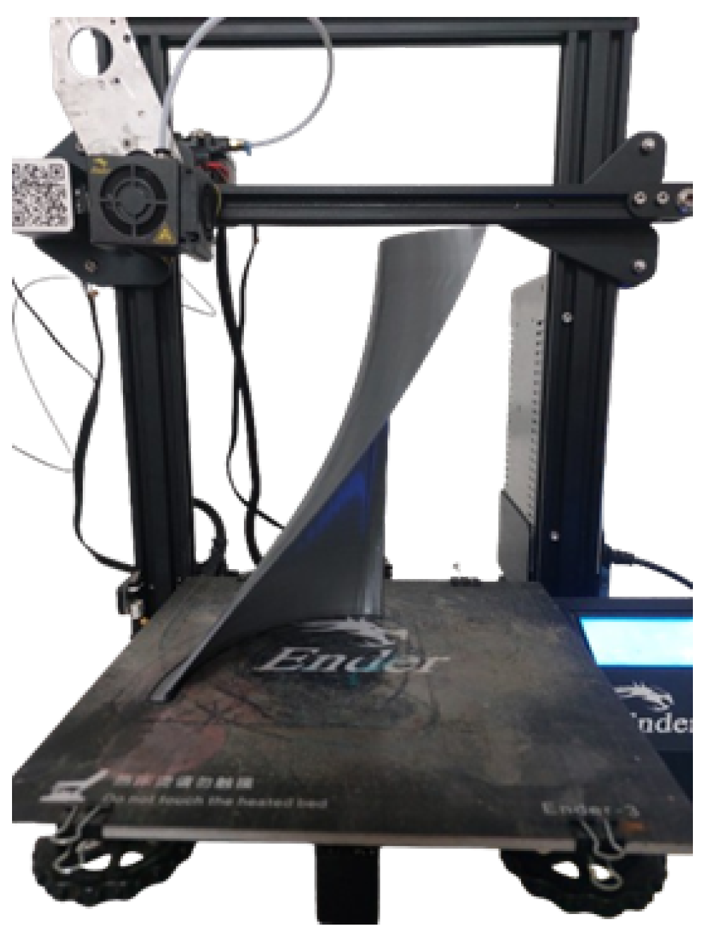
The manufacturing process for turbine rotors using natural fibers involves several key steps. First, the appropriate fique fiber material is selected and prepared. This preparation includes cleaning the selected fiber to remove impurities, ensuring that it will be suitable for integration into the composite material. Next, the natural fibers are combined with resins, either biocompatible or synthetic, to create a fiber composite material. The fibers are impregnated with resin using manual processes. The choice of resin depends on the performance needs of the rotor, with options including thermoplastic or thermosetting resins, which contribute to the mechanical strength of the material. Once the composite is prepared, it is molded into the desired blade shape using vacuum infusion, die casting, or hand lamination techniques. During molding, the resin hardens, providing structural integrity and strength to the composite. Once the blade is molded, it undergoes a curing process to ensure that the resin hardens completely, solidifying the fibers and allowing the rotor to meet the required mechanical properties. Once cured, the blades undergo finishing processes, which involve smoothing the surfaces and removing imperfections. The blades are then assembled onto the central shaft of the rotor, ensuring proper alignment and secure attachment. Finally, the rotor is tested under simulated operating conditions to assess its energy efficiency. The rotor is also checked to ensure it meets dynamic balancing and safety standards. During this stage, any necessary adjustments are made to optimize the rotor’s performance. The use of natural fibers in hydroelectric turbine rotors not only improves the sustainability of the energy system, but also offers better performance and durability, contributing to the development of more environmentally friendly hydrokinetic energy solutions. The process began with the design of the blades using Autodesk Inventor software, where geometric precision was pursued to meet hydraulic efficiency and structural stability requirements, such as blade thickness, among others. The rotor was modeled with six symmetrical blades with specific curvatures that maximize the energy conversion of the gravitational flow. The CAD model incorporated key geometric details, such as the aerodynamic profile and the length of the blades, which are decisive for the performance of the runner. Once the optimal design was finalized, only one blade was left and exported in high-resolution STL (Stereolithography) format for use in subsequent stages. The base model was then 3D printed using PLA filament. Printing was accomplished layer by layer, adjusting parameters such as nozzle temperature of 210 °C and layer speed of 30 mm/s, to obtain an accurate reproduction of the original design. The printed model, as seen in
Figure 5, served as a template to replicate the geometry of the blades, taking advantage of the properties of PLA to capture fine details and ensure accuracy in the following stages.
The next step was to manufacture the mold from the printed model. To achieve this, the piece was placed on a support structure and a mixture of polyester resin and fiberglass was applied. A fiberglass cloth of suitable size was arranged to cover the model and was subsequently impregnated with resin using a brush, ensuring uniform coverage. Once the material had solidified, the base model was removed, obtaining a precise cavity that reproduced the shape of the blade. For the manufacture of the blades, a combination of polyester resin and two layers of fique fibers as reinforcement supplied were used. The fibers were previously cut and prepared to fit the mold. Each layer was manually impregnated with polyester resin, guaranteeing complete saturation and the elimination of air bubbles. The layers were arranged following a weave pattern to optimize mechanical strength and structural uniformity. After lamination, the piece was left to cure at room temperature according to the resin manufacturer’s specifications. After curing, the blades were carefully removed to avoid damage to the edges and subjected to a manual polishing process with fine-grained abrasives as shown in
Figure 6; this improved the surface quality and aerodynamics of the parts. Additionally, individual weight control was performed to ensure uniformity, a crucial aspect to prevent imbalances and vibrations during operation. In cases where weight variations were detected, adjustments were made by fine sanding until a homogeneous distribution of mass was achieved in all the parts.
The central shaft was manufactured exclusively from polyester resin, molded into a cylindrical structure that provided the necessary rigidity and durability. For the assembly of the impeller, a special support was designed using 3D printing in PLA as seen in
Figure 7, which allowed the blades to be precisely aligned around the shaft and maintain their position during the joining process.
Finally, the blades were assembled and fixed to the shaft made of polyester resin, ensuring a firm and stable connection. The assembly was then left to cure completely to ensure optimal adhesion between the components and improve structural strength. The result was a solid and durable connection, as seen in
Figure 8.
The use of natural fibers such as fique in the construction of turbine blades presents several limitations. One of the main challenges is the natural variability of the fibers, as their properties can vary significantly depending on their origin and the treatments they undergo, which affects the reproducibility of the rotor. Additionally, while fique fibers have good tensile strength, they exhibit limited resistance to fatigue and erosion. In conditions of turbulent flow, erosion, or exposure to moisture, the fibers tend to degrade more quickly, reducing their durability. Furthermore, the high moisture absorption of fique fibers can compromise the structural integrity of the turbine. Moisture absorption can degrade the matrix or induce swelling, leading to a reduction in the dimensional and mechanical stability of the blades. Finally, fique composites tend to have a higher surface roughness compared to other materials if appropriate compaction techniques are not employed, which may negatively impact the hydraulic efficiency of the rotor.
2.5. Setup and Experimental Configuration for Rotor Testing
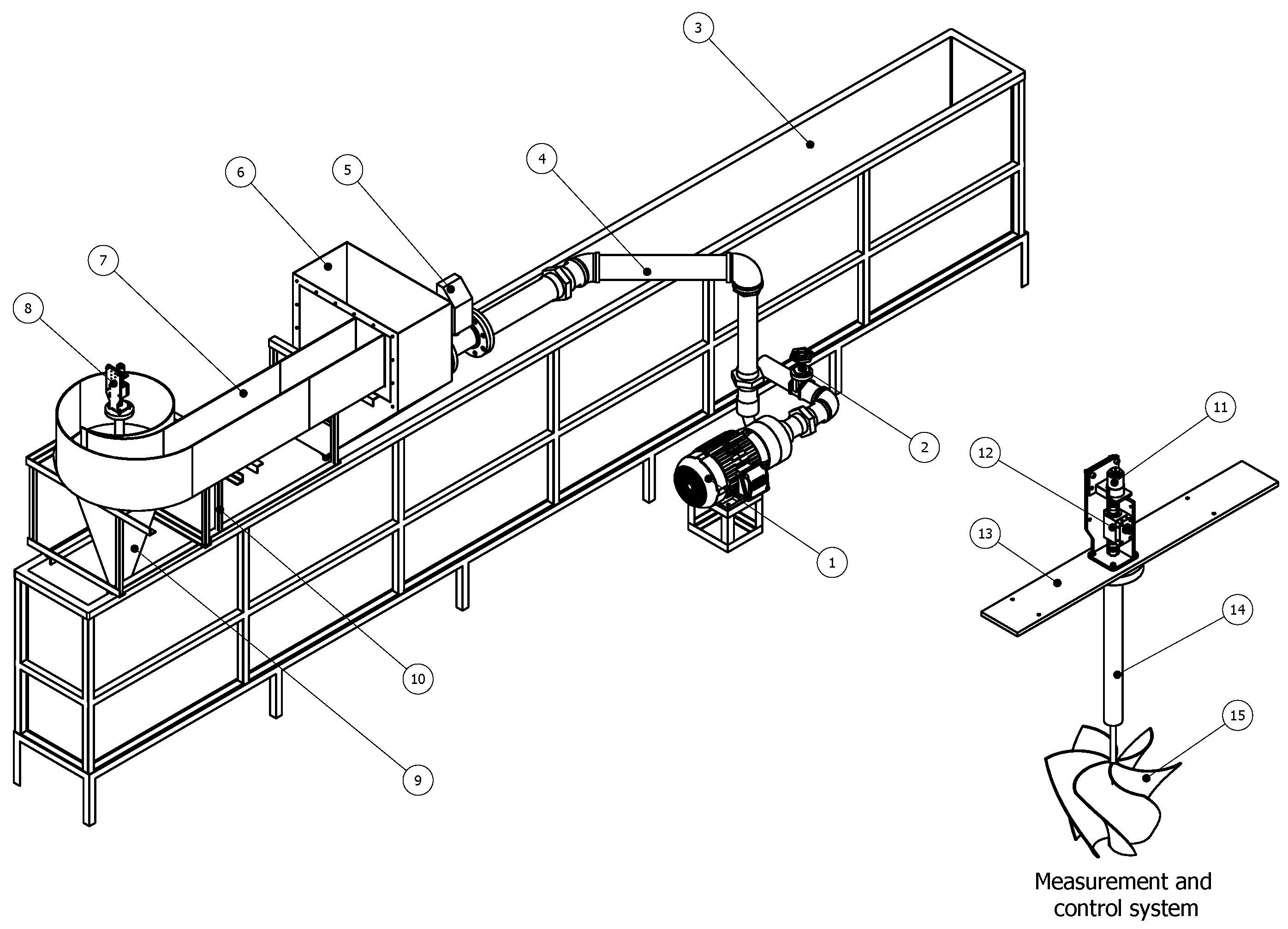
The test bench shown in
Figure 9 is designed to evaluate the performance of a gravitational vortex turbine. The test bench consists of several components. The pumping system (1) includes an electric motor coupled to a centrifugal pump that generates the required water flow to feed the test channel. A flow control system (2) is installed at the pump outlet to regulate water velocity before entering the test section. The lower tank (3) collects the water after passing through the turbine, allowing its recirculation. The supply pipe (4) transports water from the lower tank to the feeding tank (6), where the flow stabilizes before entering the test section. A flow meter (5) measures the water flow entering the system, ensuring precise control of the test conditions. The spiral inlet channel (7) directs water toward the turbine, creating a vortex flow that enhances the gravitational vortex effect. The measurement and control system (8) records key parameters such as torque and rotational speed. The discharge cone (9) facilitates water exit from the turbine, ensuring proper flow toward the lower tank while minimizing unwanted turbulence. The support structure (10) holds the feeding system and ensures the stability of the test channel. A loading motor (11) is coupled to the turbine shaft to apply a controlled mechanical load during the tests, while a torque sensor (12) measures the torque generated by the turbine. The adjustable support (13) allows modifications to the position of the measurement and control system to accommodate different experimental configurations. A vertical shaft (14) connects the turbine rotor to the measurement and control system, transmitting rotational motion. Finally, the gravitational vortex turbine (15) is submerged at the bottom of the system, harnessing the vortex-induced flow to convert water energy into mechanical energy.
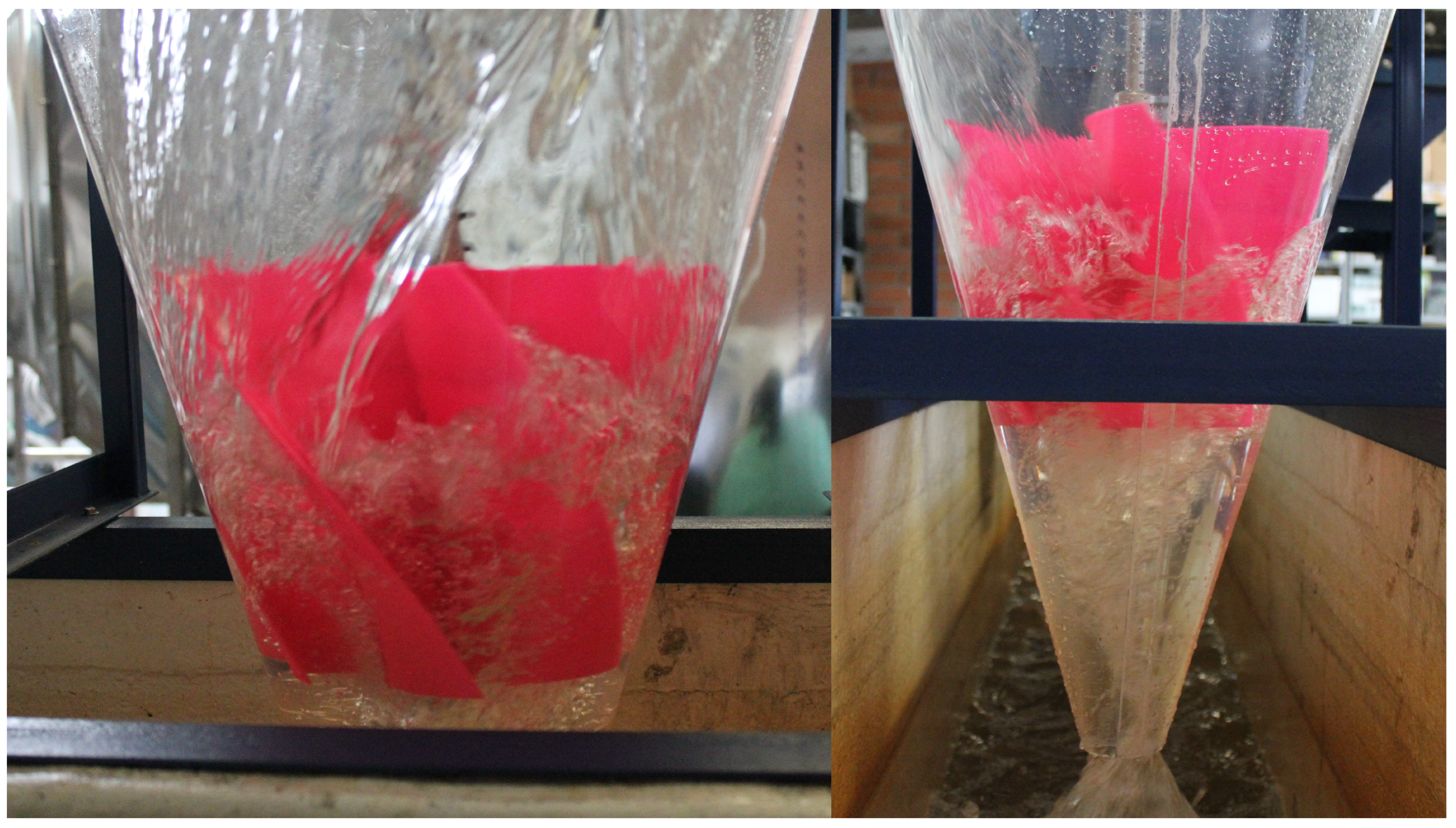
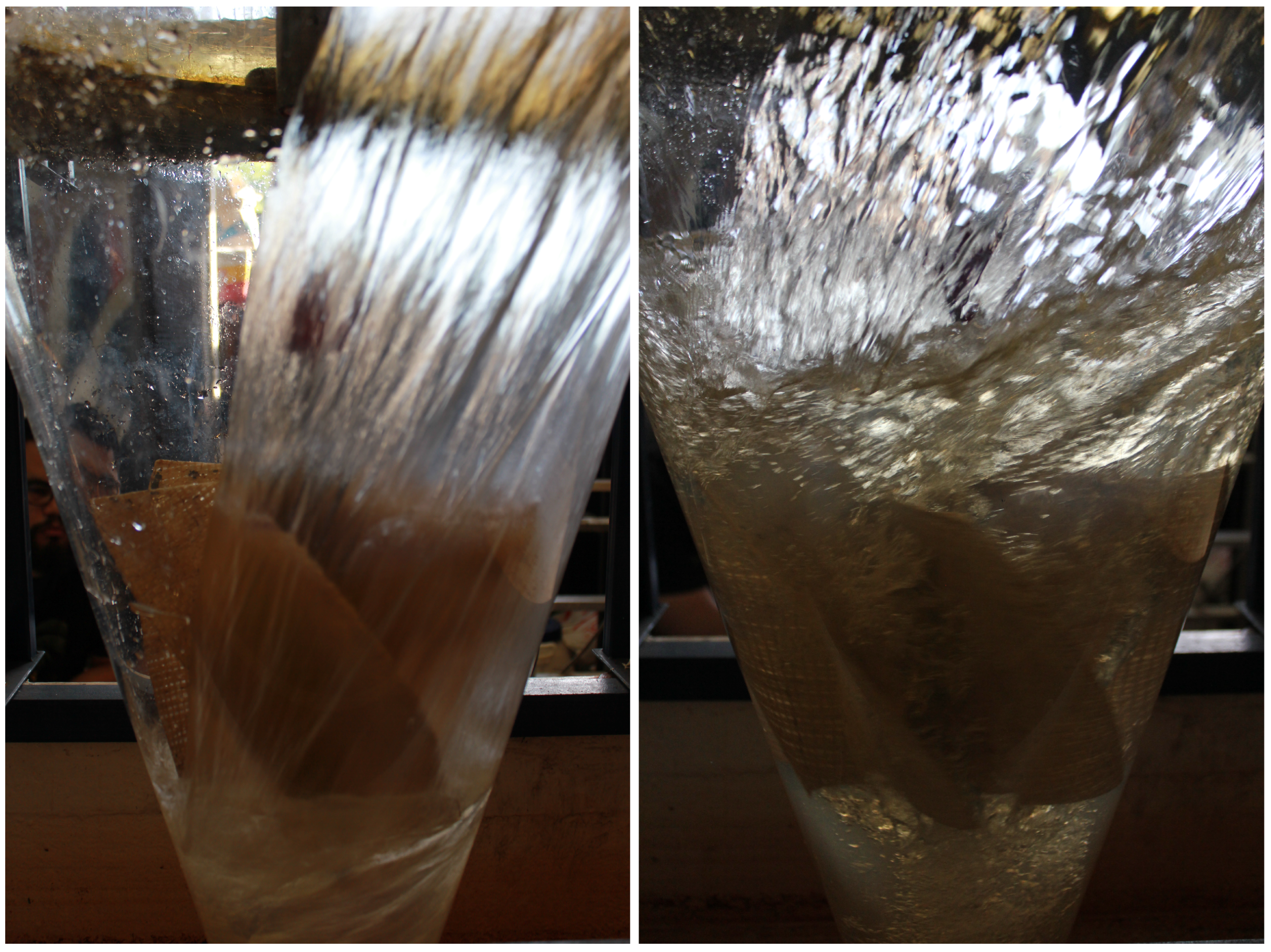
The experimental tests of the gravitational vortex turbine in the described test system follow a structured procedure. First, a specific flow rate is set, causing the fluid to rise through the pipe and fill the feeding tank. Once the tank reaches a certain level, water flows into the inlet channel, where it moves towards the discharge cone. Inside the cone, a water vortex forms, driving the rotation of the turbine. The measurement and control system records the turbine’s rotational velocity and torque. The sensor, through a connection to a computer, provides real-time values of torque and rotational speed under the different testing conditions.
Next, the motor coupled to the control system is powered, applying a load to the rotor and gradually slowing its rotation. As the current and voltage supplied to the rotor increase, the load intensifies, further reducing the rotor’s speed. This process is repeated incrementally until the rotor comes to a complete stop. The procedure is conducted multiple times to obtain the turbine’s performance curve. The tests were performed at two flow rates, 2.5 L/s and 3.0 L/s, and for two different rotors: Rotor 1, made of PLA, and Rotor 2, made of natural fiber.
Possible sources of measurement errors in the experimental setup include sensor inaccuracies, signal noise, mechanical misalignments, and flow instabilities. Torque and rotational speed measurements may be affected by slight miscalibrations of the sensor or variations in the connection between the rotor and the measuring shaft. Additionally, fluctuations in the flow rate due to turbulence or inconsistent valve regulation can introduce variability in the turbine’s performance data. To minimize these errors, all sensors were calibrated prior to testing, and measurements were taken multiple times to ensure repeatability. The flow was regulated using a constant head in the feeding tank to reduce instabilities, and the mechanical components were carefully aligned and checked for looseness or asymmetry. Data were recorded in real time and averaged over short intervals to smooth out transient variations and improve the reliability of the results.
4. Conclusions
The manufacturing of the rotor of the gravitational vortex turbine using composite materials and natural fibers represents a significant advance in engineering, demonstrating that it is possible to develop new sustainable materials applicable to hydraulic turbines. This study marks a first step towards optimizing the manufacturing process, allowing for improving rotor efficiency, optimizing material use, and reducing costs compared to traditional methods. Rotor 1, made of PLA, outperforms Rotor 2, made of natural fiber, in terms of efficiency. At a flow rate of 3.0 L/s, Rotor 1 achieves a peak efficiency of approximately 0.65 at around 160 RPM. In contrast, under the same flow conditions, Rotor 2 exhibits significantly lower efficiency, remaining below 0.20 and peaking at approximately 140 RPM. While the efficiency metrics of fique fiber rotors may show a performance deficit compared to their PLA counterparts, their inherent material properties offer distinct advantages in specific operational contexts. In such scenarios, the trade-off between efficiency and durability favors the use of fique fiber, ensuring prolonged and reliable performance in challenging environments. The selection of the natural fiber-based biocomposite was presented as a viable alternative for rotor manufacturing. Furthermore, proper curing of the polyester resin shaft guaranteed a firm and stable connection between the blades and the shaft, contributing to the structural durability of the assembly. Reinforcement with natural fibers allowed a significant reduction in weight compared to conventional materials, while maintaining adequate mechanical performance. This feature is especially beneficial in renewable energy applications, where structural efficiency is a key factor.
Nevertheless, several limitations and challenges were encountered during this study. The use of the manual rolling method, while accessible and cost-effective, posed significant difficulties in achieving uniform surface quality and consistent adhesion between layers, which are critical for maintaining a homogeneous blade thickness. Additionally, ensuring dynamic balance in the rotor proved challenging, directly affecting the turbine’s operational performance and lifespan. Vibrations resulting from imbalance not only reduced efficiency but also risked inducing structural damage over time. The handmade manufacturing process also introduced variability in the rotor dimensions, influencing the reproducibility of results. Future research should explore alternative fabrication techniques, such as vacuum infusion, to enhance the mechanical properties, surface finish, and durability of the rotors made with natural fibers. Additionally, optimizing fiber orientation and resin curing parameters could further improve structural integrity and overall turbine performance.


 ,
, 


