

Generation of Mechanical Characteristics in Workpiece Subsurface Layers through Milling


Abstract
1. Introduction
2. Brief Description of the State of the Art on the Determination of Mechanical Characteristics from Machined Subsurface Layers
3. Materials and Methods
3.1. Materials

| Material | Ti | Al | V | Fe | C | N | H | O | Other |
|---|---|---|---|---|---|---|---|---|---|
| Ti10V2Fe3Al | 82.86–86.8% | 2.6–3.4 | 9.0–11% | 1.6–2.2% | <0.05% | <0.05% | <0.015% | <0.13% | ≤0.3% |
| Material | Strength (MPa) | Elastic Modulus (GPa) | Elongation (%) | Hardness | Poisson′s Ratio | Specific Heat (J/kg·K) | Thermal Expansion (µm/m·°C) | Thermal Conductivity (W/m·K) | |
|---|---|---|---|---|---|---|---|---|---|
| Tensile | Yield | ||||||||
| Ti10V2Fe3Al | 1282 | 1220 | 110 | 4–10 | HV 430 | 0.35 | 527 | 9.7 | 7.0 |
| Milling cutter | - | - | 650 | - | HV 1550 | 0.25 | 251 | - | 59 |
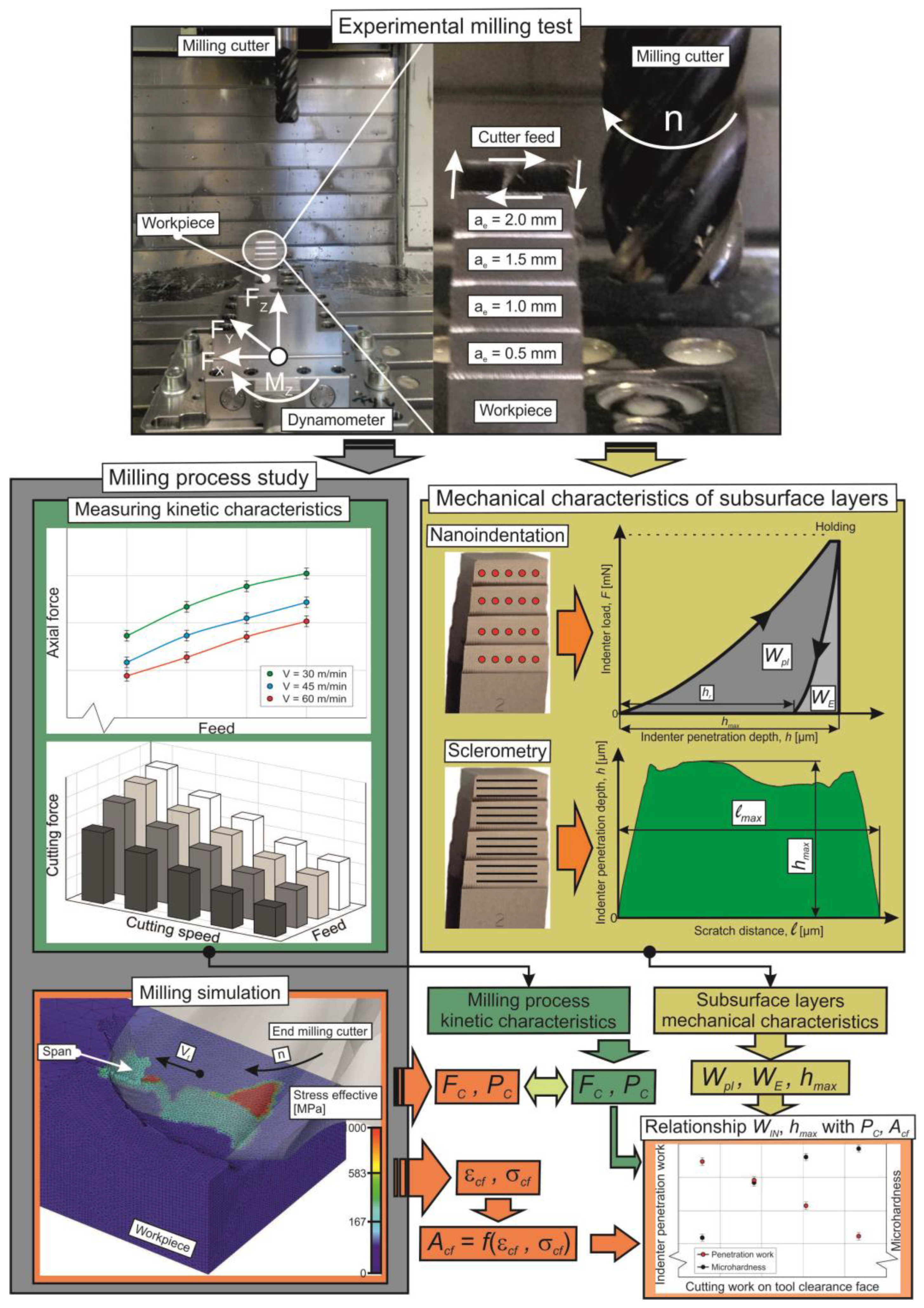
3.2. Methods
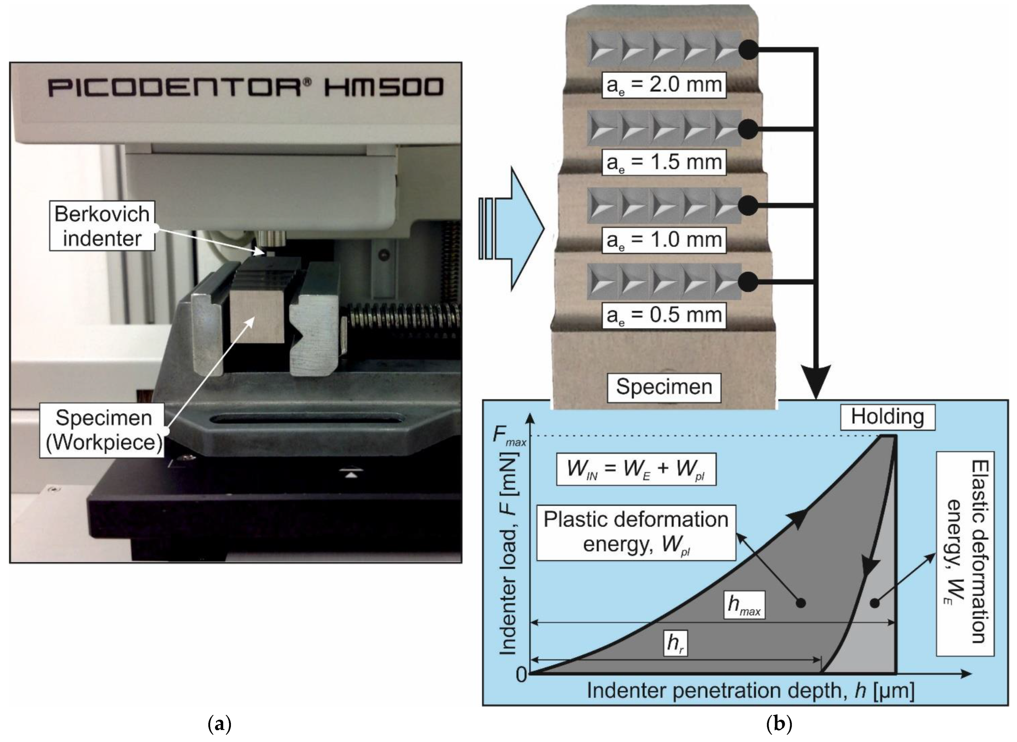
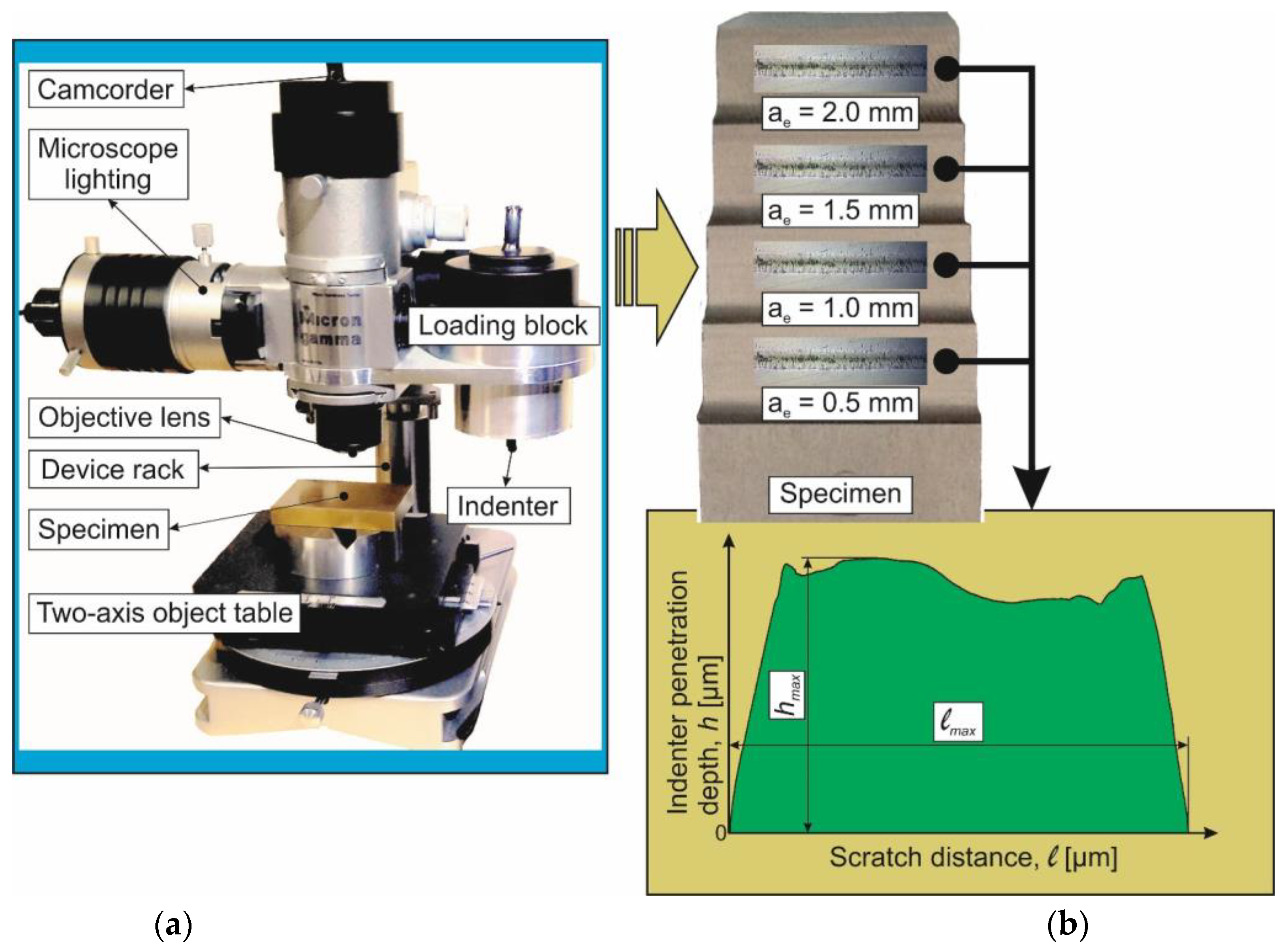
- The thermomechanical interaction of the end cutter with the machined workpiece is evaluated using the total milling power and is proportional to the indenter penetration work in the workpiece machined surface, determined using the instrumented nanoindentation of the machined subsurface layers, and proportional to the maximum depth of the indenter penetration in the subsurface layers, determined using the sclerometry of the machined subsurface layers:where is the existence space of cutting process states (conditions); SC is the cutting process state; PC is the total cutting power; WIN is the total indenter penetration work through the instrumented nanoindentation of the milled surface; and hmax is the maximum indenter penetration depth during the sclerometry of the milled surface.
- The thermomechanical interaction of the end cutter with the machined workpiece is evaluated through the plastic deformation work of the machined material in the tertiary cutting zone during milling and is proportional to the indenter penetration work in the workpiece machined surface, determined using the instrumented nanoindentation of the machined subsurface layers, and proportional to the maximum depth of the indenter penetration in the subsurface layers, determined using the sclerometry of the machined subsurface layers:
4. Results and Discussion
5. Conclusions
- ➢
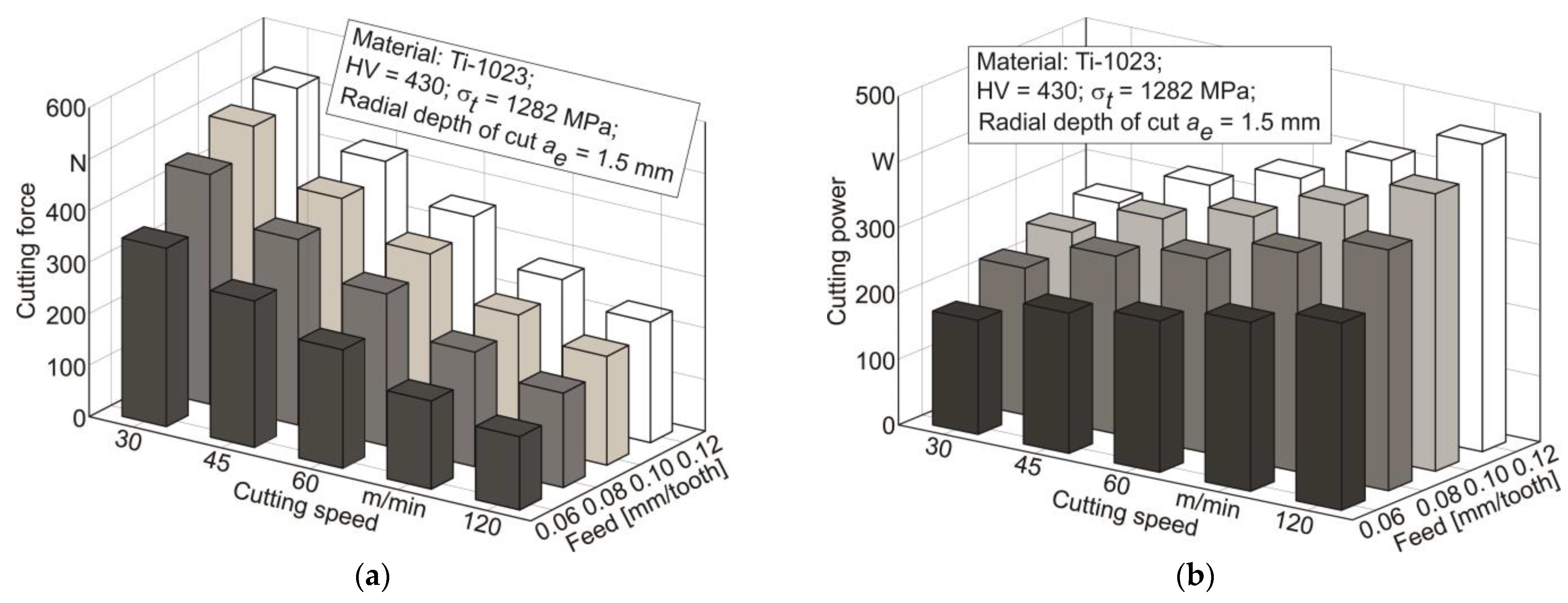
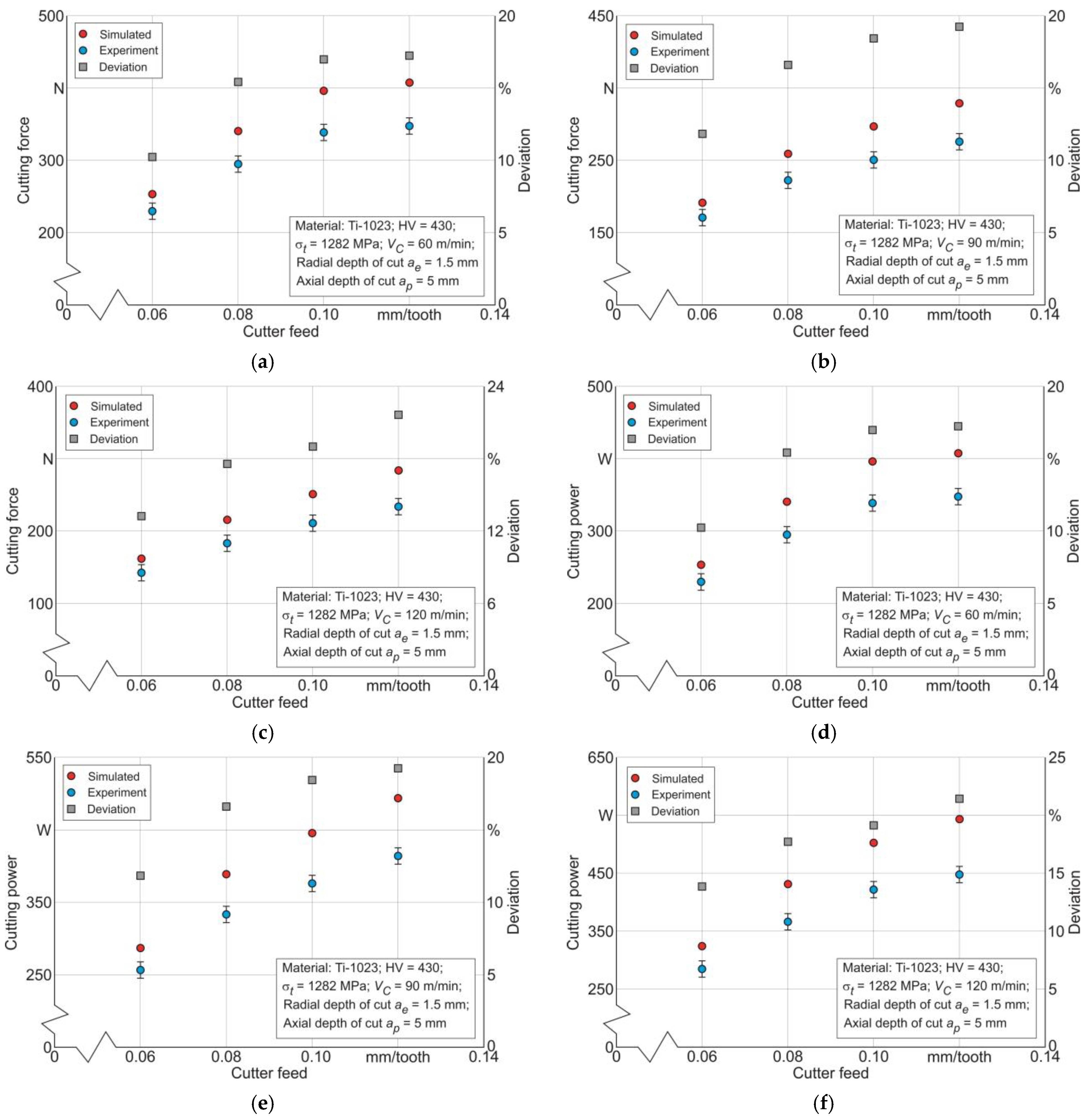
- The resulting cutting force monotonically increases with increasing cutter feed and decreases monotonically with increasing cutting speed;
- ➢
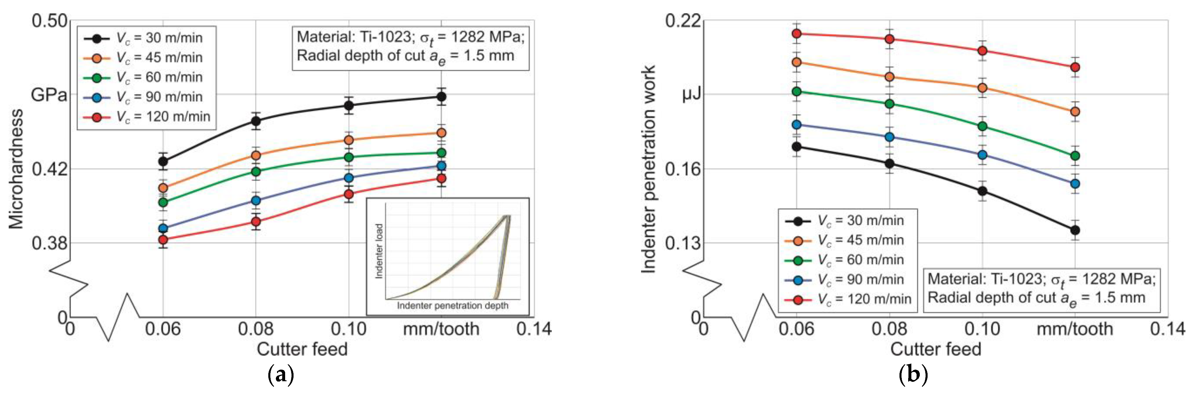
- The microhardness of the workpiece subsurface layers monotonically increases with increasing cutter feed and decreases with increasing cutting speed;
- ➢
- The indenter penetration work as a result of the instrumented nanoindentation of the workpiece subsurface layers decreases with increasing cutter feed and increases with increasing cutting speed;
- ➢
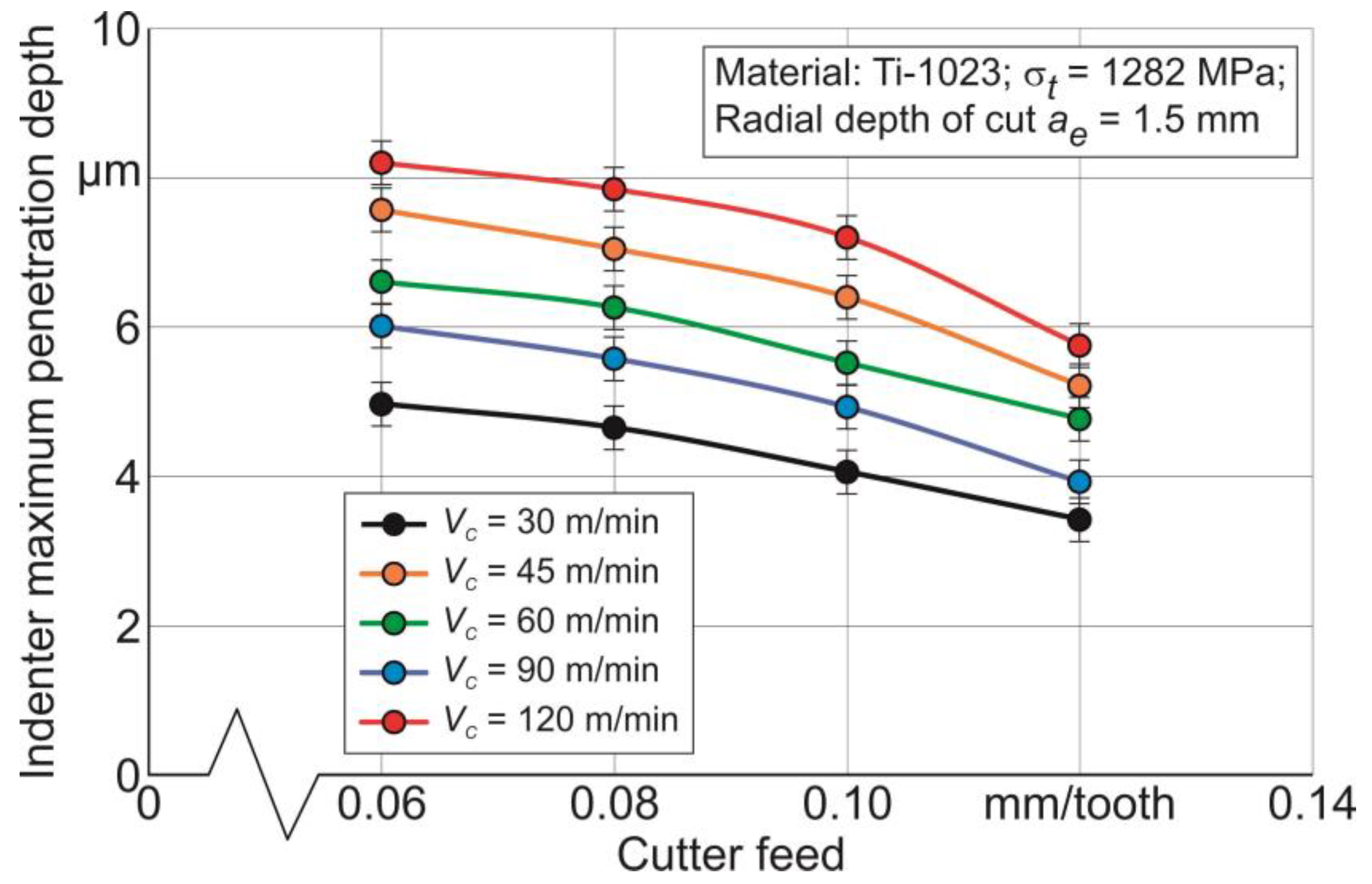
- The indenter maximum penetration depth as a result of the sclerometry of the workpiece subsurface layers decreases with increasing cutter feed and increases with increasing cutting speed.
- ➢
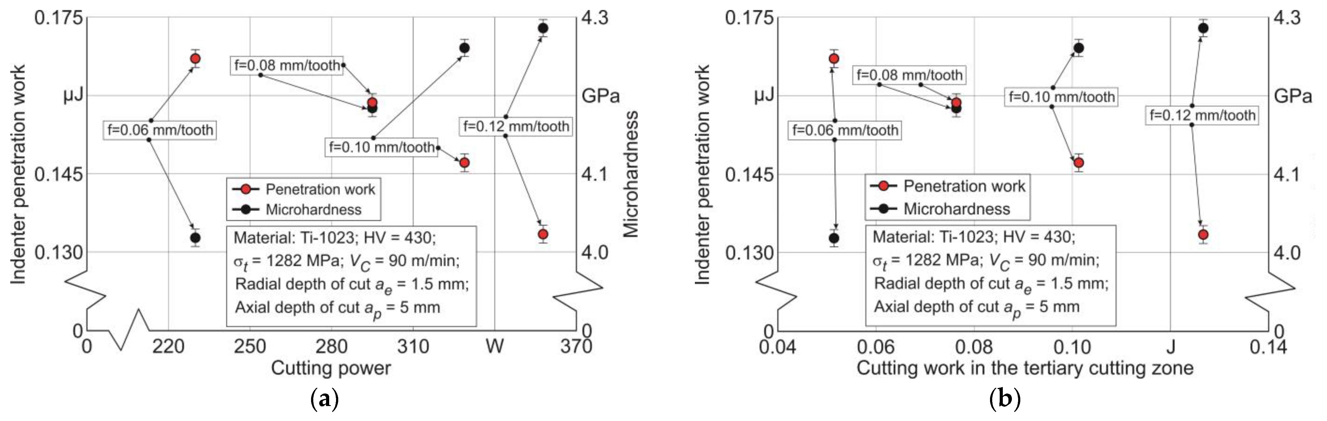
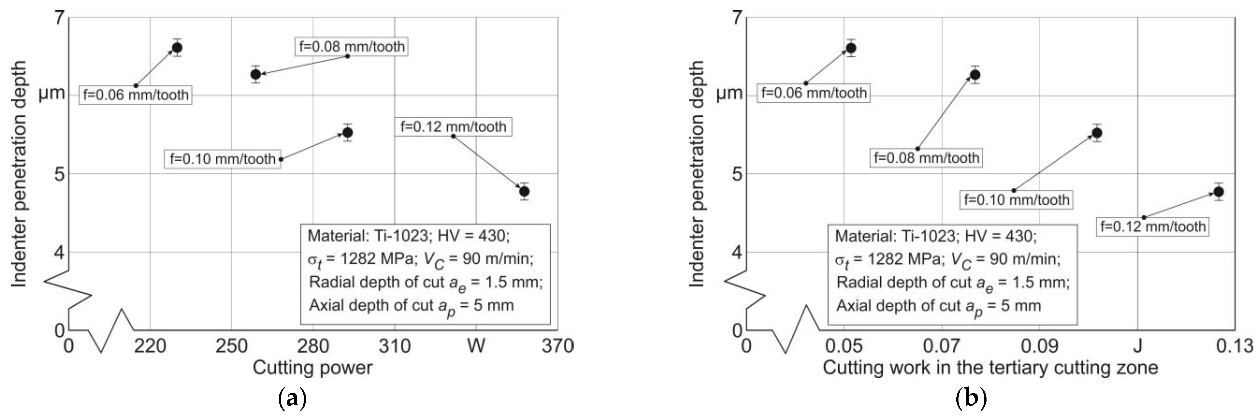
- The cutting power increases both with increasing cutting speed and with increasing cutter feed;
- ➢
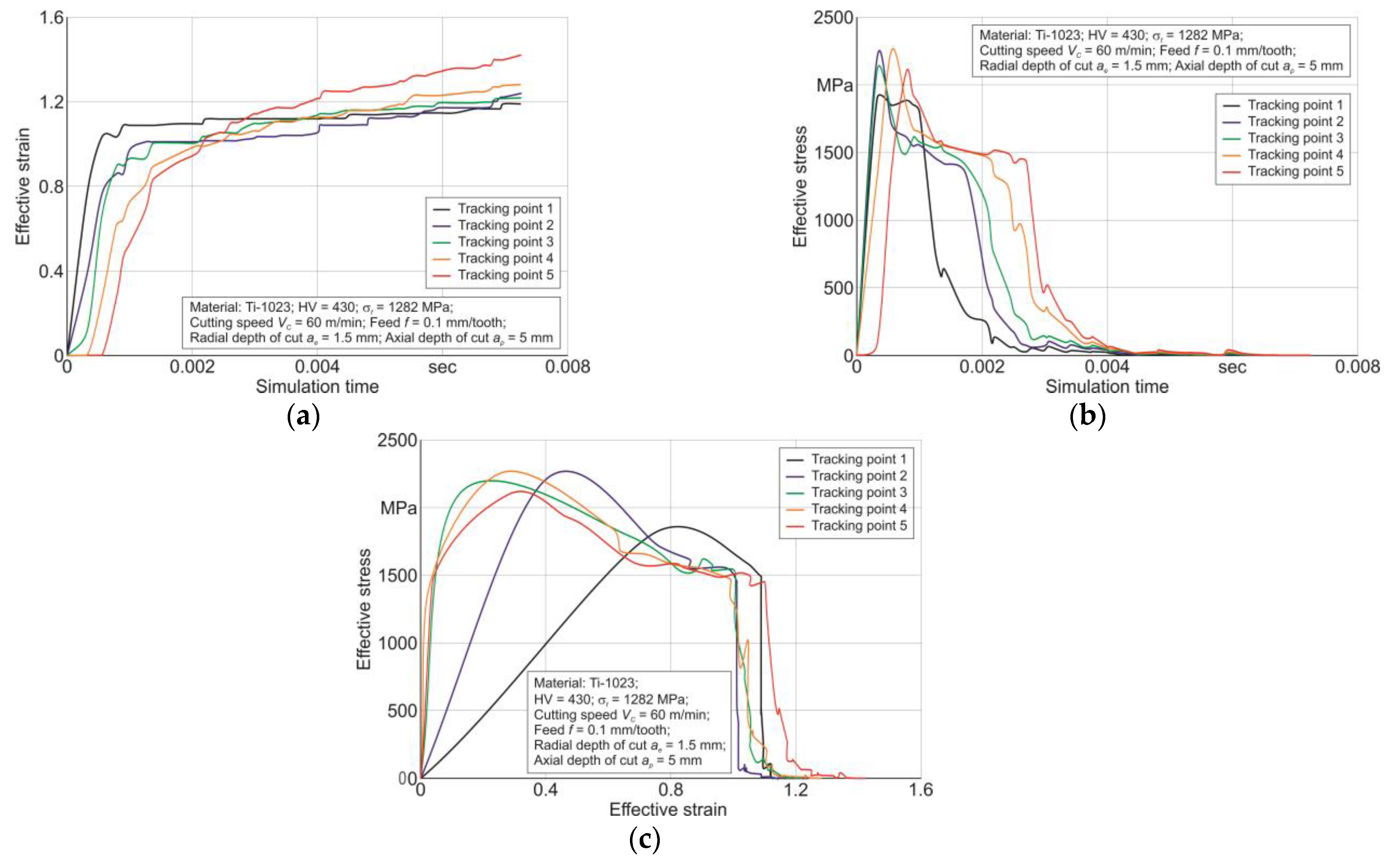
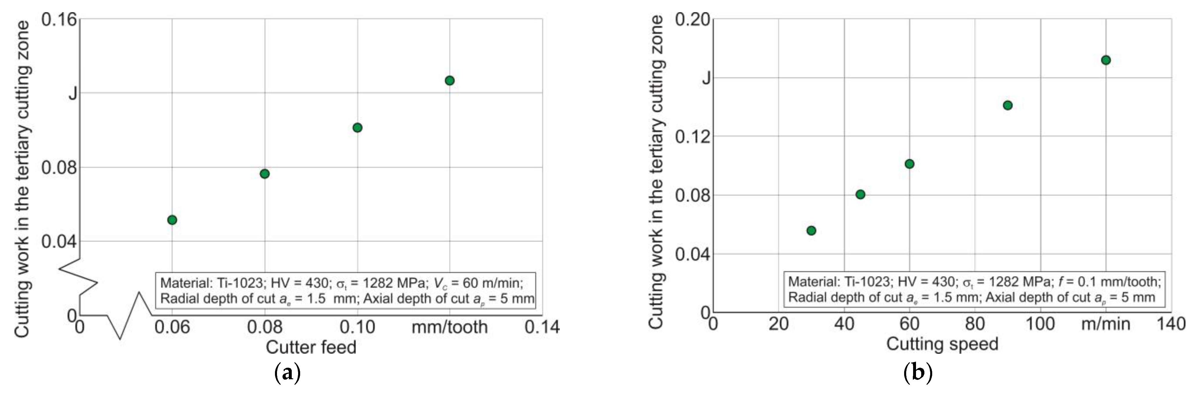
- The cutting work in the tertiary cutting zone increases both with increasing cutter feed and with increasing cutting speed.
Author Contributions
Funding
Institutional Review Board Statement
Informed Consent Statement
Data Availability Statement
Acknowledgments
Conflicts of Interest
References
- Sagapuram, D.; Udupa, A.; Viswanathan, K.; Mann, J.B.; M’saoubi, R.; Sugihara, T.; Chandrasekar, S. On the Cutting of Metals: A Mechanics Viewpoint. ASME J. Manuf. Sci. Eng. 2020, 142, 110808. [Google Scholar] [CrossRef]
- Guo, Y.; Saldana, C.; Compton, W.D.; Chandrasekar, S. Controlling deformation and microstructure on machined surfaces. Acta Mater. 2011, 59, 4538–4547. [Google Scholar] [CrossRef]
- Bag, R.; Panda, A.; Sahoo, A.K.; Kumar, R. A Perspective Review on Surface Integrity and Its Machining Behavior of AISI 4340 Hardened Alloy Steel. Mater. Today Proc. 2019, 18, 3532–3538. [Google Scholar] [CrossRef]
- Soori, M.; Arezoo, B. A Review in Machining-Induced Residual Stress. J. New Technol. Mater. 2022, 12, 64–83. Available online: https://hal.science/hal-03679993 (accessed on 11 February 2024).
- Saptaji, K.; Afiqah, S.; Ramdan, R. A Review on Measurement Methods for Machining Induced Residual Stress. Indonesian J. Comput. Eng. Des. (IJoCED) 2019, 1, 106–120. [Google Scholar] [CrossRef]
- Pan, Z.; Feng, Y.; Liang, S. Material microstructure affected machining: A review. Manuf. Rev. 2017, 4, 5. [Google Scholar] [CrossRef]
- Luo, L.; Pang, J.; Song, Y.; Liu, S.; Yin, G.; Peng, H.; Pu, C.; Lin, Y.; Li, J.; Shi, X. Microstructure Evolution Mechanism of AISI 1045 Steel under High Speed Deformation. Arch. Metall. Mater. 2023, 68, 1525–1531. [Google Scholar] [CrossRef]
- M’Saoubi, R.; Outeiro, J.C.; Chandrasekaran, H.; Dillon, O.W., Jr.; Jawahir, I.S. A review of surface integrity in machining and its impact on functional performance and life of machined products. Int. J. Sustain. Manuf. 2008, 1, 203–236. [Google Scholar] [CrossRef]
- Malakizadi, A.; Bertolini, R.; Ducobu, F.; Kilic, Z.; Magnanini, M.C.; Shokrani, A. Recent advances in modelling and simulation of surface integrity in machining—A review. Procedia CIRP 2022, 115, 232–240. [Google Scholar] [CrossRef]
- Davim, J.P. Machining of Complex Sculptured Surfaces; Springer: London, UK, 2012; 258p. [Google Scholar] [CrossRef]
- Babichev, D.; Storchak, M. Synthesis of cylindrical gears with optimum rolling fatigue strength. Prod. Eng. Res. Dev. 2015, 9, 87–97. [Google Scholar] [CrossRef]
- Ulutan, D.; Ozel, T. Machining induced surface integrity in titanium and nickel alloys: A review. Int. J. Mach. Tools Manuf. 2011, 51, 250–280. [Google Scholar] [CrossRef]
- Kanaev, A.T.; Ramazanova, Z.M.; Biizhanov, S.K. Study of plasma-hardened wheel steel using nanoindentation. Industrial laboratory. Diagn. Mater. 2020, 86, 56–60. (In Russian) [Google Scholar] [CrossRef]
- Oila, A.; Bull, S.J. Nanoindentation testing of gear steels. Int. J. Mater. Res. 2003, 94, 793–797. [Google Scholar] [CrossRef]
- Randall, N.X. The current state-of-the-art in scratch testing of coated systems. Surf. Coat. Technol. 2019, 380, 125092. [Google Scholar] [CrossRef]
- Li, J.; Beres, W. Scratch Test for Coating/Substrate Systems—A Literature Review. Can. Metall. Q. 2007, 46, 155–173. [Google Scholar] [CrossRef]
- Storchak, M. Mechanical Characteristics Generation in the Workpiece Subsurface Layers through Cutting. Crystals 2023, 13, 761. [Google Scholar] [CrossRef]
- Sinha, M.K.; Pal, A.; Kishore, K.; Singh, A.; Archana; Sansanwal, H.; Sharma, P. Applications of sustainable techniques in machinability improvement of superalloys: A comprehensive review. Int. J. Interact. Des. Manuf. 2023, 17, 473–498. [Google Scholar] [CrossRef]
- Dai, X.; Zhuang, K.; Pu, D.; Zhang, W.; Ding, H. An Investigation of the Work Hardening Behavior in Interrupted Cutting Inconel 718 under Cryogenic Conditions. Materials 2020, 13, 2202. [Google Scholar] [CrossRef]
- Ren, X.; Liu, Z. Influence of cutting parameters on work hardening behavior of surface layer during turning superalloy Inconel 718. Int. J. Adv. Manuf. Technol. 2016, 86, 2319–2327. [Google Scholar] [CrossRef]
- Xu, D.; Ding, L.; Liu, Y.; Zhou, J.; Liao, Z. Investigation of the Influence of Tool Rake Angles on Machining of Inconel 718. J. Manuf. Mater. Process. 2021, 5, 100. [Google Scholar] [CrossRef]
- Lu, X.; Jia, Z.; Wang, H.; Feng, Y.; Liang, S.Y. The effect of cutting parameters on micro-hardness and the prediction of Vickers hardness based on a response surface methodology for micro-milling Inconel 718. Measurement 2019, 140, 56–62. [Google Scholar] [CrossRef]
- Xavior, A.; Manohar, M.; Madhukar, P.M.; Jeyapandiarajan, P. Experimental investigation of work hardening, residual stress and microstructure during machining Inconel 718. J. Mech. Sci. Technol. 2017, 31, 4789–4794. [Google Scholar] [CrossRef]
- Suárez, A.; Veiga, F.; Polvorosa, R.; Artaza, T.; Holmberg, J.; de Lacalle, L.L.; Wretland, A. Surface integrity and fatigue of non-conventional machined Alloy 718. J. Manuf. Process. 2019, 48, 44–50. [Google Scholar] [CrossRef]
- Hou, G.; Li, A. Effect of Surface Micro-Hardness Change in Multistep Machining on Friction and Wear Characteristics of Titanium Alloy. Appl. Sci. 2021, 11, 7471. [Google Scholar] [CrossRef]
- Mathoho, I.; Akinlabi, E.T.; Mybiayi, M.P.; Mbohwa, C. Effect of milling parameters on microhardness and microstructure during dry and flood milling of Ti-6Al-4V. IOP Conf. Ser. Mater. Sci. Eng. 2018, 423, 012161. [Google Scholar] [CrossRef]
- Monka, P.P.; Monkova, K.; Vasina, M.; Kubisova, M.; Korol, M.; Sekerakova, A. Effect of Machining Conditions on Temperature and Vickers Microhardness of Chips during Planing. Metals 2022, 12, 1605. [Google Scholar] [CrossRef]
- Wang, X. Intelligent Prediction of Surface Micro-hardness after Milling Based on Smooth Support Vector Regression. In Proceedings of the International Symposium on Knowledge Acquisition and Modeling, Wuhan, China, 21–22 December 2008; pp. 728–731. [Google Scholar] [CrossRef]
- Dos Santos, C.E.; Carneiro, J.R.G.; da Silva, G.C.; Brito, P.P.; dos Santos, B.; Campos, T.R. Residual stress and surface microhardness post-milling in 2205 duplex steel. Int. J. Adv. Manuf. Technol. 2021, 113, 3445–3455. [Google Scholar] [CrossRef]
- Rangasamy, N.; Rakurty, C.S.; Balaji, A.K. A Multiscale Study on Machining Induced Surface Integrity in Ti-6Al-4V Alloy. Procedia CIRP 2022, 108, 787–792. [Google Scholar] [CrossRef]
- Wang, Z.-Y.; Ren, J.-X.; Zhou, J.-H.; Cai, J. Correlation analysis of microstructure evolution on microhardness and residual stress for cutting Ti-6Al-4V titanium alloy. Proc. Inst. Mech. Eng. Part B J. Eng. Manuf. 2023, 237, 885–898. [Google Scholar] [CrossRef]
- Mendas, M.; Benayoun, S.; Miloud, M.H.; Zidane, I. Microhardness model based on geometrically necessary dislocations for heterogeneous material. J. Mater. Res. Technol. 2021, 15, 2792–2801. [Google Scholar] [CrossRef]
- Ameri, A.A.H.; Elewa, N.N.; Ashraf, M.; Escobedo-Diaz, J.P. General methodology to estimate the dislocation density from microhardness measurements. Mater. Charact. 2017, 131, 324–330. [Google Scholar] [CrossRef]
- Alijani, A.; Amini, R.; Ghaffari, M.; Alizadeh, M.; Okyay, A.K. Effect of milling time on the structure, micro-hardness, and thermal behavior of amorphous/nanocrystalline TiNiCu shape memory alloys developed by mechanical alloying. Mater. Des. 2014, 55, 373–380. [Google Scholar] [CrossRef]
- Chen, Z.; Huang, C.; Li, B.; Jiang, G.; Tang, Z.; Niu, J.; Liu, H. Experimental study on surface integrity of Inconel 690 milled by coated carbide inserts. Int. J. Adv. Manuf. Technol. 2022, 121, 3025–3042. [Google Scholar] [CrossRef]
- Haddag, B.; Yameogo, D.; Nouari, M.; Makich, H. Multi-Physics Analysis of Machining Ti-6Al-4V Alloy: Experimental Characterization and a New Material Behavior Modeling. Metals 2022, 12, 581. [Google Scholar] [CrossRef]
- da Silva, R.H.L.; Schoop, J.; Hassui, A.; Jawahir, I.S. Inconel 625 sustainable milling surface integrity and the dependence on alloy processing route. Int. J. Adv. Manuf. Technol. 2024, 130, 4493–4512. [Google Scholar] [CrossRef]
- Rajguru, R.R.; Vasudevan, H. A study of micro hardness in the machining of Inconel 625 using TiAlSiN coated tools under dry cutting conditions. Adv. Mater. Process. Technol. 2022, 8, 120–130. [Google Scholar] [CrossRef]
- Harun, S.; Burhanuddin, Y.; Ibrahim, G.A. The Effect of Cutting Parameters on Surface Roughness and Morphology of Ti-6Al-4V ELI Titanium Alloy during Turning with Actively Driven Rotary Tools. J. Manuf. Mater. Process. 2022, 6, 105. [Google Scholar] [CrossRef]
- Pharr, G.M. Recent advances in small-scale mechanical property measurement by nanoindentation. Curr. Opin. Solid State Mater. Sci. 2015, 19, 315–316. [Google Scholar] [CrossRef]
- Fischer-Cripps, A.C. Critical review of analysis and interpretation of nanoindentation test data. Surf. Coat. Technol. 2006, 200, 4153–4165. [Google Scholar] [CrossRef]
- Li, X.; Bhushan, B. A review of nanoindentation continuous stiffness measurement technique and its applications. Mater. Charact. 2002, 48, 11–36. [Google Scholar] [CrossRef]
- Wredenberg, F.; Larsson, P.-L. Scratch testing of metals and polymers: Experiments and numerics. Wear 2009, 266, 76–83. [Google Scholar] [CrossRef]
- Kolawole, O.; Ispas, I. Evaluation of geomechanical properties via scratch tests: Where are we and where do we go from here? SN Appl. Sci. 2020, 2, 1633. [Google Scholar] [CrossRef]
- Atkins, A.G.; Tabor, D. Plastic Indentation in Metals with Cones. J. Mech. Phys. Solids 1965, 13, 149–164. [Google Scholar] [CrossRef]
- Doerner, M.; Nix, W. A method for interpreting the data from depth-sensing indentation instruments. J. Mater. Res. 1986, 1, 601–609. [Google Scholar] [CrossRef]
- Oliver, W.C.; Pharr, G.M. An improved technique for determining hardness and elastic modulus using load and displacement sensing indentation experiments. J. Mater. Res. 1992, 7, 1564–1583. [Google Scholar] [CrossRef]
- Pethica, J.B.; Hutchings, R.; Oliver, W.C. Hardness Measurement at Penetration Depths as Small as 20 nm. Philos. Mag. A 1983, 48, 593–606. [Google Scholar] [CrossRef]
- Fischer-Cripps, A.C. Nanoindentation, 2nd ed.; Springer: Berlin/Heidelberg, Germany, 2011; 276p. [Google Scholar] [CrossRef]
- Lin, C.K.; Berndt, C.C. Measurement and analysis of adhesion strength for thermally sprayed coatings. J. Therm. Spray Technol. 1994, 3, 75–104. [Google Scholar] [CrossRef]
- Bull, S.J. Failure modes in scratch adhesion testing. Surf. Coat. Technol. 1991, 50, 25–32. [Google Scholar] [CrossRef]
- Zivic, F.; Babic, M.; Adamovic, D.; Mitrovic, S.; Todorovic, P.; Favaro, G.; Pantić, M. Influence of the surface roughness on adhesion of chrome coatings on alloy tool steel x165crmov12. J. Balk. Tribol. Assoc. 2012, 18, 228–237. [Google Scholar]
- Sousa, F.J.P.; Tridapalli, D.; Pereira, M.; Flesch, C.A.; Alarcon, O.E. Evaluation of measurement uncertainties for a scratching tester. Measurement 2006, 39, 594–604. [Google Scholar] [CrossRef]
- Yildiz, F.; Asaran, A. Multi-pass scratch test behavior of modified layer formed during plasma nitriding. Tribol. Int. 2010, 43, 1472–1478. [Google Scholar] [CrossRef]
- Storchak, M.; Zakiev, I.; Träris, L. Mechanical properties of subsurface layers in the machining of the titanium alloy Ti10V2Fe3Al. J. Mech. Sci. Technol. 2018, 32, 315–322. [Google Scholar] [CrossRef]
- Li, Z.; Herrmann, K.; Pohlenz, F. A comparative approach for calibration of the depth measuring system in a nanoindentation instrument. Measurement 2006, 39, 547–552. [Google Scholar] [CrossRef]
- Peng, G.; Xu, F.; Chen, J.; Hu, Y.; Wang, H.; Zhang, T. A cost-effective voice coil motor-based portable micro-indentation device for in situ testing. Measurement 2020, 165, 108105. [Google Scholar] [CrossRef]
- Ding, K.; Zhang, Y.; Birnbaum, A.J.; Michopoulos, J.G.; McDowell, D.L.; Zhu, T. Strain gradient plasticity modeling of nanoindentation of additively manufactured stainless steel. Extrem. Mech. Lett. 2021, 49, 101503. [Google Scholar] [CrossRef]
- Fritz, R.; Kiener, D. Development and application of a heated in-situ SEM micro-testing device. Measurement 2017, 110, 356–366. [Google Scholar] [CrossRef]
- Vargas, A.L.M.; Blando, E.; Hübler, R. Elasto—Plastic materials behavior evaluation according to different models applied in indentation hardness tests. Measurement 2019, 139, 134–139. [Google Scholar] [CrossRef]
- Kang, J.J.; Becker, A.A.; Wen, W.; Sun, W. Extracting elastic-plastic properties from experimental loading-unloading indentation curves using different optimization techniques. Int. J. Mech. Sci. 2018, 144, 102–109. [Google Scholar] [CrossRef]
- Guillonneau, G.; Kermouche, G.; Bec, S.; Loubet, J.-L. Determination of mechanical properties by nanoindentation independently of indentation depth measurement. J. Mater. Res. 2012, 27, 2551–2560. [Google Scholar] [CrossRef]
- Harsono, E.; Swaddiwudhipong, S.; Liu, Z.S. The effect of friction on indentation test results. Model. Simul. Mater. Sci. Eng. 2008, 16, 065001. [Google Scholar] [CrossRef]
- Wang, Y. Effects of indenter angle and friction on the mechanical properties of film materials. Results Phys. 2016, 6, 509–514. [Google Scholar] [CrossRef][Green Version]
- Sivaram, S.; Jayasinghe, J.A.S.C.; Bandara, C.S. Qualitative Study on Pile-up Effect on Hardness Test by Nano-Indentation. Eng. J. Inst. Eng. 2021, 54, 47–55. [Google Scholar] [CrossRef]
- Farayibi, P.K.; Hankel, J.; Hassend, F.v.G.; Blüm, M.; Weber, S.; Röttger, A. Tribological characteristics of sintered martensitic stainless steels by nano-scratch and nanoindentation tests. Wear 2023, 512–513, 204547. [Google Scholar] [CrossRef]
- Tsybenko, H.; Farzam, F.; Dehm, G.; Brinckmann, S. Scratch hardness at a small scale: Experimental methods and correlation to nanoindentation hardness. Tribol. Int. 2021, 163, 107168. [Google Scholar] [CrossRef]
- England, J.; Uddin, M.J.; Ramirez-Cedillo, E.; Karunarathne, D.; Nasrazadani, S.; Golden, T.D.; Siller, H.R. Nanoindentation Hardness and Corrosion Studies of Additively Manufactured 316 L Stainless Steel. J. Mater. Eng. Perform. 2022, 31, 6795–6805. [Google Scholar] [CrossRef]
- Moon, J.; Kim, S.; Jang, J.; Lee, J.; Lee, C. Orowan strengthening effect on the nanoindentation hardness of the ferrite matrix in microalloyed steels. Mater. Sci. Eng. A 2008, 487, 552–557. [Google Scholar] [CrossRef]
- Li, C.; Zhao, H.; Sun, L.; Yu, X. In situ nanoindentation method for characterizing tensile properties of AISI 1045 steel based on mesomechanical analysis. Adv. Mech. Eng. 2019, 11, 1687814019862919. [Google Scholar] [CrossRef]
- Paul, V.; Ameyama, K.; Ota-Kawabata, M.; Ohmura, T. Evaluation of Deformation and Fracture Behavior in 304 L Austenitic Steel Harmonic Structures through Nanoindentation. Steel Res. Int. 2023, 94, 2200354. [Google Scholar] [CrossRef]
- Yang, L.; Sun, K.; Peng, W.; Li, X.; Zhang, L. Effects of Grain Boundary Angles on Initial Deformation of 304 Austenitic Stainless Steel under Nanoindentation: A Molecular Dynamics Simulation. Crystals 2022, 12, 58. [Google Scholar] [CrossRef]
- Zhou, G.; Guo, J.; Zhao, J.; Tang, Q.; Hu, Z. Nanoindentation Properties of 18CrNiMo7-6 Steel after Carburizing and Quenching Determined by Continuous Stiffness Measurement Method. Metals 2020, 10, 125. [Google Scholar] [CrossRef]
- Dean, J.; Aldrich-Smith, G.; Clyne, T.W. Use of nanoindentation to measure residual stresses in surface layers. Acta Mater. 2011, 59, 2749–2761. [Google Scholar] [CrossRef]
- Wang, H.; Zhu, L.; Xu, B. Residual Stresses and Nanoindentation Testing of Films and Coatings; Springer Nature Singapore Pte Ltd.: Singapore; Science Press: Beijing, China, 2018; 207p, ISBN 978-981-10-7840-8. [Google Scholar] [CrossRef]
- Zhang, W.; Wang, X.; Hu, Y.; Wang, S. Predictive modelling of microstructure changes, micro-hardness and residual stress in machining of 304 austenitic stainless steel. Int. J. Mach. Tools Manuf. 2018, 130–131, 36–48. [Google Scholar] [CrossRef]
- Aurich, J.C.; Steffes, M. Single Grain Scratch Tests to Determine Elastic and Plastic Material Behavior in Grinding. Adv. Mater. Res. 2011, 325, 48–53. [Google Scholar] [CrossRef]
- Fan, P.; Katiyar, N.K.; Zhou, X.; Goel, S. Uniaxial pulling and nano-scratching of a newly synthesised high entropy alloy. APL Mater. 2022, 10, 111118. [Google Scholar] [CrossRef]
- Pratap, A.; Divse, V.; Goel, S.; Joshi, S.S. Understanding the surface generation mechanism during micro-scratching of Ti-6Al-4V. J. Manuf. Process. 2022, 82, 543–558. [Google Scholar] [CrossRef]
- Liu, H.; Xu, X.; Zhang, J.; Liu, Z.; He, Y.; Zhao, W.; Liu, Z. The state of the art for numerical simulations of the effect of the microstructure and its evolution in the metal-cutting processes. Int. J. Mach. Tools Manuf. 2022, 177, 103890. [Google Scholar] [CrossRef]
- Bezyazychnyy, V.F.; Prokofev, M.A.; Vinogradova, N.V. Research of the Influence of Technological Machining Conditions on the Accumulation of Latent Energy Deformation in the surface Parts. Bull. PNIPU Aerosp. Eng. 2015, 43, 131–144. [Google Scholar] [CrossRef]
- Yamamoto, M.; Tanaka, M.; Furukimi, O. Hardness–Deformation Energy Relationship in Metals and Alloys: A Comparative Evaluation Based on Nanoindentation Testing and Thermodynamic Consideration. Materials 2021, 14, 7217. [Google Scholar] [CrossRef] [PubMed]
- Wang, Q.; Liu, Z.; Wang, B.; Song, Q.; Wan, Y. Evolutions of grain size and micro-hardness during chip formation and machined surface generation for Ti-6Al-4V in high-speed machining. Int. J. Adv. Manuf. Technol. 2016, 82, 1725–1736. [Google Scholar] [CrossRef]
- Storchak, M.; Stehle, T.; Möhring, H.-C. Numerical Modeling of Titanium Alloy Ti10V2Fe3Al Milling Process. J. Manuf. Mater. Process. 2023, 7, 132. [Google Scholar] [CrossRef]
- Material Property Data. Available online: http://www.matweb.com (accessed on 19 April 2019).
- Storchak, M.; Jiang, L.; Xu, Y.; Li, X. Finite element modeling for the cutting process of the titanium alloy Ti10V2Fe3Al. Prod. Eng. Res. Dev. 2016, 10, 509–517. [Google Scholar] [CrossRef]
- Storchak, M.; Stehle, T.; Möhring, H.-C. Determination of thermal material properties for the numerical simulation of cutting processes. Int. J. Adv. Manuf. 2021, 118, 1941–1956. [Google Scholar] [CrossRef]
- Zorev, N.N. Metal Cutting Mechanics; Pergamon Press GmbH: Frankfurt am Main, Germany, 1966; 526p, ISBN 978-0080107233. [Google Scholar]
- Oxley, P.L.B. Development and Application of a Predictive Machining Theory. Mach. Sci. Technol. 1998, 2, 165–189. [Google Scholar] [CrossRef]
- Kushner, V.; Storchak, M. Modelling the Material Resistance to Cutting. Int. J. Mech. Sci. 2017, 126, 44–54. [Google Scholar] [CrossRef]
- Heisel, U.; Kushner, V.; Storchak, M. Effect of machining conditions on specific tangential forces. Prod. Eng. 2012, 6, 621–629. [Google Scholar] [CrossRef]
- Tsekhanov, J.; Storchak, M. Development of analytical model for orthogonal cutting. Prod. Eng. Res. Dev. 2015, 9, 247–255. [Google Scholar] [CrossRef]
- Johnson, G.R.; Cook, W.H. A constitutive model and data for metals subjected to large strains, high strain and high temperatures. In Proceedings of the 7th International Symposium on Ballistics, The Hague, The Netherlands, 19–21 April 1983; pp. 541–547. [Google Scholar]
- Heisel, U.; Krivoruchko, D.V.; Zaloha, W.A.; Storchak, M.; Stehle, T. Thermomechanical material models in the modeling of cutting processes. ZWF Z. Fuer Wirtsch. Fabr. 2009, 104, 482–491. [Google Scholar] [CrossRef]
- Heisel, U.; Krivoruchko, D.V.; Zaloha, W.A.; Storchak, M.; Stehle, T. Thermomechanical exchange effects in machining. ZWF Z. Fuer Wirtsch. Fabr. 2009, 104, 263–272. [Google Scholar] [CrossRef]
- Storchak, M.; Möhring, H.-C.; Stehle, T. Improving the friction model for the simulation of cutting processes. Tribol. Int. 2022, 167, 107376. [Google Scholar] [CrossRef]
- Heisel, U.; Krivoruchko, D.V.; Zaloha, W.A.; Storchak, M.; Stehle, T. Breakage models for the modeling of cutting processes. ZWF Z. Fuer Wirtsch. Fabr. 2009, 104, 330–339. [Google Scholar] [CrossRef]
- Cockroft, M.G.; Latham, D.J. Ductility and workability of metals. J. Inst. Met. 1968, 96, 33–39. [Google Scholar] [CrossRef]
- Kushner, V.; Storchak, M. Determining mechanical characteristics of material resistance to deformation in machining. Prod. Eng. Res. Dev. 2014, 8, 679–688. [Google Scholar] [CrossRef]
- Kushner, V.; Storchak, M. Determination of Material Resistance Characteristics in Cutting. Procedia CIRP 2017, 58, 293–298. [Google Scholar] [CrossRef]
- Storchak, M.; Kushner, V.; Möhring, H.-C.; Stehle, T. Refinement of temperature determination in cutting zones. J. Mech. Sci. Technol. 2021, 35, 3659–3673. [Google Scholar] [CrossRef]


Disclaimer/Publisher’s Note: The statements, opinions and data contained in all publications are solely those of the individual author(s) and contributor(s) and not of MDPI and/or the editor(s). MDPI and/or the editor(s) disclaim responsibility for any injury to people or property resulting from any ideas, methods, instructions or products referred to in the content. |
© 2024 by the authors. Licensee MDPI, Basel, Switzerland. This article is an open access article distributed under the terms and conditions of the Creative Commons Attribution (CC BY) license (https://creativecommons.org/licenses/by/4.0/).
Share and Cite
Storchak, M.; Hlembotska, L.; Melnyk, O. Generation of Mechanical Characteristics in Workpiece Subsurface Layers through Milling. Materials 2024, 17, 1552. https://doi.org/10.3390/ma17071552
Storchak M, Hlembotska L, Melnyk O. Generation of Mechanical Characteristics in Workpiece Subsurface Layers through Milling. Materials. 2024; 17(7):1552. https://doi.org/10.3390/ma17071552
Chicago/Turabian StyleStorchak, Michael, Larysa Hlembotska, and Oleksandr Melnyk. 2024. "Generation of Mechanical Characteristics in Workpiece Subsurface Layers through Milling" Materials 17, no. 7: 1552. https://doi.org/10.3390/ma17071552
APA StyleStorchak, M., Hlembotska, L., & Melnyk, O. (2024). Generation of Mechanical Characteristics in Workpiece Subsurface Layers through Milling. Materials, 17(7), 1552. https://doi.org/10.3390/ma17071552