1. Introduction
Due to the excellent physical properties of graphene, graphene-based nano-reinforcements are identified as a kind of promising candidate for the reinforcement phases of polymer matrix nanocomposites [
1]. An increasing number of scientists are working to apply them to the design of micro/nanoscale devices, including nanosensors, nanoactuators, nanotransducers, and biosensors [
2,
3,
4,
5]. Of all of the graphene-based nanofillers, graphene nanoplates (GPLs), with their high specific surface area and high surface-to-mass ratio, provide several special advantages to develop high performance advanced nanocomposites with a wide range of possible applications [
6,
7]. The mechanical performances of nanocomposites can be substantially improved by dispersing a low content of GPLs. The elastic modulus and tensile strength of the pure epoxy can be improved by 31% and 53%, respectively, through adding GPLs [
8]. In addition, the benefits of GPLs are critically dependent on the GPL distribution pattern within the matrix. Under the development of functionally graded materials (FGMs), functionally graded GPL-reinforced nanocomposites (FG-GPLRCs) are created as an exclusive category of advanced non-homogeneous nanocomposites [
9,
10]. Kitipornchai et al. [
11] carried out an analysis of the elastic buckling and free vibration of FG-GPLRC porous beams. Feng et al. [
9] studied the nonlinear bending of non-uniformly distributed GPL-reinforced polymer nanocomposite beams. Wu et al. [
12] performed the dynamic stability analysis of FG-GPLRC beams. Yang et al. [
13] analyzed the buckling/postbuckling of FG-GPLRC multilayer beams. In addition, the static and dynamic characteristics of FG-GPLRC plate- [
14,
15], shell- [
16,
17], and arche-like [
18,
19] structures were examined carefully.
Upon reviewing the aforementioned research, there has been a significant focus on incorporating GPL content grading in the structural thickness direction. However, axially functionally graded (AFG) beams are extensively used in a variety of engineering fields, e.g., the automotive industry, helicopter rotor blades, MEMS, and turbine blades. The AFG-GPLRCs will allow a novel tailored fit to control the mechanical responses of nanocomposite structures, such as the buckling resistance and dynamic behaviors over a pre-specified level. It can be anticipated that the combination of both axial and thickness directions for beam-like structures will yield the best functional grading. Hein and Feklistova [
20] showed the results of a free vibration of the AFGM beam using the method of Haar wavelets. Rokni et al. [
21] focused on the optimal multi-walled carbon nanotubes (MWCNTs) distribution within a polymer composite microbeam to maximize its dynamic behaviors while using a fixed amount of MWCNTs. Their findings revealed that a non-uniform axial dispersion of MWCNTs resulted in higher natural frequencies compared to that of a uniform distribution pattern. This suggests that carefully controlling the dispersion pattern of MWCNTs can significantly enhance the performance of microbeams in terms of their vibrational characteristics. El-Ashmawy and Xu [
22] demonstrated that the axially graded CNTs led to notable improvements in mechanical properties such as stiffness, strength, and durability. Rezaiee-Pajand et al. [
23] introduced the Hencky bar-chain model to investigate the buckling behavior of AFG-composite beams, considering the axially graded distribution of carbon nanotubes. It should be noted that, the analyses for AFG beams have become more complicated because of the governing equation with variable coefficients, and great efforts have been made to try to solve the four-order differential equations as mentioned above. Liang et al. [
24] established linear and nonlinear isogeometric finite element models of an AFG-GPLRC curved beam within the framework of the third-order shear deformation beam theory and von-Karman’s nonlinear geometric relation. Recently, Liu et al. [
25] developed the state-space method to examine the impact of an axially varying dispersion of GPLs on the stability and dynamic behaviors of AFG-GPLRC beams subjected to edge (compressive) loads.
Thin beams have indeed found significant applications in micro-electro-mechanical systems (MEMS), such as those in vibration shock sensors, biosensors, etc. In those applications, the beam mostly falls within the size of microns and sub-microns, and it is common to observe a size-dependent behavior in the deformation [
26]. Nateghi et al. [
27] revealed that the size dependency of FG microbeams is much higher than that of macro-beams. Wang et al. [
28] employed the modified couple stress theory (MCST) and the von Karman nonlinearity for the vibration analysis of microbeams. Allahkarami and Tohidi [
29] applied MCST into checking the geometrically nonlinear vibration of multilayer FG-GPLRC microbeam. Yin et al. [
30] put forward an analytical solution and employed an isogeometric approach for a comprehensive investigation of the buckling analysis of size-dependent microbeams. Nguyen et al. [
31] developed a Chebyshev–Ritz solution to investigate bending, vibration, and buckling responses of porous microbeams. Soltani et al. [
32] investigated the comprehensive study of the vibration control of multi-layer sandwich composite piezoelectric microbeams.
Indeed, most of the buckling studies on beams often consider the presence of end compressive loads. However, in real-world scenarios, beams often experience axially varying compressive loads along the beam length. This variation in compressive load can be due to factors such as distributed loads, bending moments, or other external forces acting on the beam. Karamanli and Aydogdu [
33] focused on studying the elastic buckling behavior of beams made of isotropic materials, laminated composites, and sandwich structures subjected to various axially varying in-plane loads. Eltaher et al. [
34] used a differential quadrature method (DQM) to examine the static stability and mode-shapes of axially varying in-plane loaded composite laminated beams. Masjedi and Weaver [
35] derived an analytical solution for three-dimensional static deflection of composite beams that experience non-uniformly distributed axial loads. Howaon and Williams [
36] presented a dynamic stiffness matrix analysis on the vibration of a beam-column with axially loaded Timoshenko members. Naguleswaran [
37] examined the transverse vibration of beams under linearly varying axial force. Bargozini et al. [
38] studied the critical buckling load for a sandwich composite beam reinforced with carbon nanorods in the bottom and top layers under variable axial forces based on the sinusoidal shear deformation theory.
As indicated by the literature review, there has been a significant amount of research dedicated to FG-GPLRC structures. However, based on the available literature, it appears that the static and dynamic behaviors of AFG-GPLRC microbeams subjected to axially varying loads have not been extensively studied or clearly addressed. For axially graded microbeams, similar problems become more complicated because of the governing equation with variable coefficients, which is quite difficult to solve analytically or numerically. So far, few solutions are found for arbitrary gradient change due to the difficulty of the mathematical treatment of the problem, save certain special gradients. The objective of the present paper is to discuss the buckling and vibration characteristics of axially functionally graded (AFG) graphene platelets reinforced (GPLRC) nanocomposite microbeams subjected to different types of axially varying loads (AVLs). The GPL nano-reinforcements are dispersed into an epoxy matrix throughout the beam length in the uniform and non-uniform patterns, while the non-uniform distributions of GPLs yield the axially functionally graded nanocomposites. In the meantime, the linear and nonlinear forms of AVLs are taken into consideration. By combining the improved Halpin–Tsai model and the rule of mixtures, the effective material properties of AFG-GPLRCs are calculated. The governing equations are derived on the assumptions of the Euler–Bernoulli beam theory, and the MSCT is adopted to capture the scale effect of microbeams. The state-space method is developed to derive the governing equation of the eigenvalue problems, and a first-order differential equation in matrix form is obtained. To solve the governing equation with variable coefficients, the length-direction discrete model composed of equilong segmentations is employed. The characteristic equations are finally established for various boundary conditions by using the continuous conditions of the fictitious interfaces of the discrete model, and are solved numerically. To examine the synergetic influences of the axial grading of GPLs and AVLs on the size-dependence buckling and dynamic characteristics, numerical studies are carried out in terms of the small scale, distribution patterns, and geometric parameters of GPLs, and various types of AVLs.
3. Solution Procedure
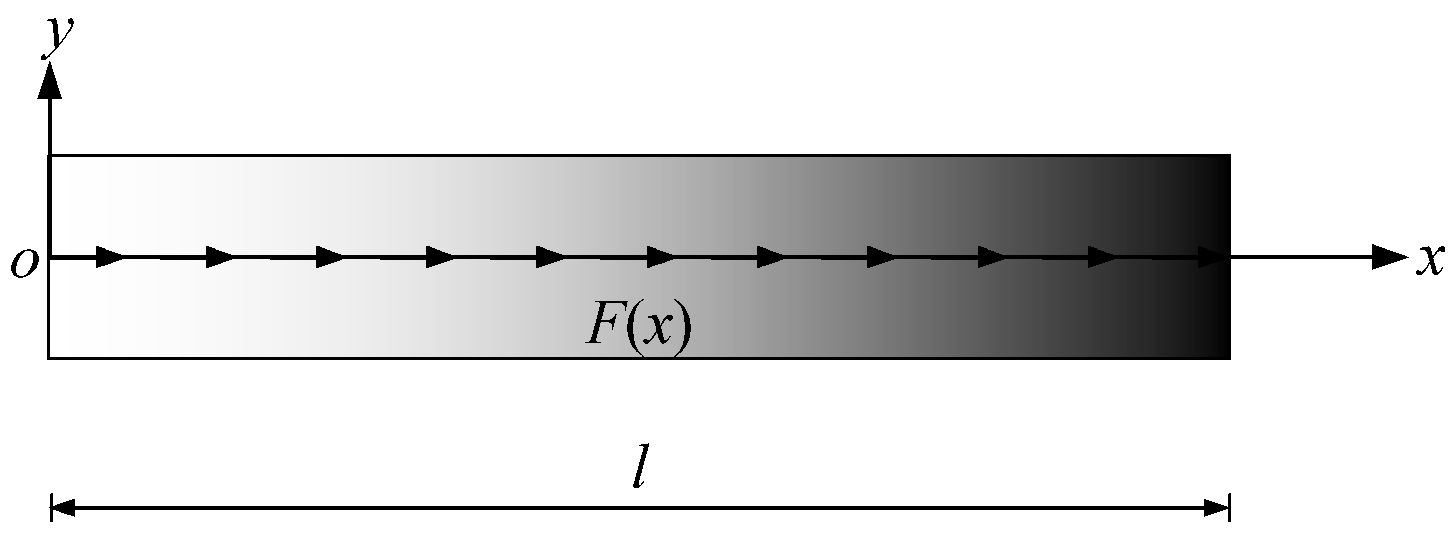
The governing Equation (17) is a variable-coefficient ordinary differential equation, and is quite difficult to solve analytically. To facilitate the numerical calculations, the microbeam is split into a series of identical length segments
along its length direction with a large enough value of
N, as shown in
Figure 5. The material properties of each sufficiently short segment are thought of as constant, resulting in matrix
independent of
ξ.
For the
jth segment, the governing equation, Equation (17), is
where
and
represent contiguous coordinates of the segment, and
. The solution for Equation (19) is
Setting
leads to
The continuity conditions of adjacent segments yield
in which
and
are the state vectors of the microbeam’s two ends, respectively, and
denotes the microbeam transfer matrix.
Three typical end boundary conditions of the microbeams, namely simply supported (S), clamped (C), and free (F) ends, are herein considered as
, simply supported end;
, clamped end;
, free end.
For the SS microbeam, Equation (22) gives
in which
is the element of the global transfer matrix
R. The non-zero solution for the first and third equations in Equation (23) requires
which is the characteristic equation of SS microbeams.
Similarly, the corresponding characteristic equation for the CC microbeam is
The characteristic equation for the CF microbeam gives
Equations (24)–(27) show two eigenvalue problems which lead to the calculation of vibration frequencies and buckling loads for the AFG-PLRC microbeams, and can be solved with numerical methods.
4. Numerical Results
In this section, the present formulations are applied herein to examine the stability and vibration characteristics of AFG-GPLRC microbeams. Firstly, numerical examples are carried out to validate the accuracy and convergence of the present method. Then the buckling load and vibration frequency of AFG-GPLRC microbeams with AVLs are studied. In the calculations, the parameters in
Table 2 are used.
Unless otherwise indicated, the geometrical parameters of GPL nano-reinforcements are fixed as: , , and , respectively. The slenderness ratio of the microbeam is set to be , and the GPL weight fraction is preferred as WGPL = 1%. The number N of segments is taken as 200 to maintain sufficient convergence.
Equations (24)–(27) are transcendental equations about the nondimensional vibration frequency Ω, and the critical buckling loads can be calculated by setting Ω = 0 for the corresponding boundary conditions. In the present study, the bisection method with the aid of Matlab R2022a is conducted to find the roots of the transcendental equation.
4.1. Validation
Furthermore, to validate the present model, a unit-length beam consisting of AFGMs without considering size effects, i.e.,
, are examined. The Young’s modulus
E of the AFGM beam [
37] takes the form of
, while the mass density
ρ is chosen as
.
Table 3 lists the parameters for the frequency
of the AFGM beams, and compares these to the existing results from the literature. It shows good agreement between our results and the available previous results.
The validations of the free vibration and buckling load calculations of a linearly axial-loaded isotropic beam were also conducted. The vibration frequency and buckling parameters predicted by the proposed model match well, as shown in
Table 4 and
Table 5, in which the parameters in the tables can be found in Ref. [
36].
4.2. Buckling Analysis of AFG-GPLRC Microbeams
The influence of the material length scale, axial distribution pattern of GPLs, types of axially varying load, and boundary condition on the critical buckling load
of AFG-GPLRC microbeams are presented in
Table 6,
Table 7,
Table 8 and
Table 9. For comparison, the results of pure epoxy microbeams are also given. It is discovered that the buckling resistance of the nanocomposite microbeams could be greatly increased by a low percentage of GPL nanofillers. With a dispersion of 1% weight fraction of GPLs in AFG-O SS microbeams, it is over five times higher than the buckling load of a pure-epoxy case. This is because the presence of GPL nanofillers enhances the effective material properties, resulting in increased flexural beam stiffness. Additionally, the axially graded pattern of GPLs significantly influences the buckling resistance. The table results show that GPL nanofillers have a significant enhancing impact on various types of axial load distributions. Among the studied GPL distributions, the AFG-V pattern for CC beams reaches a higher buckling load for the symmetric parabolic load, in which the axial distributions of GPLs and the applied load are nearly coincident along beam length. Among all of the axially varying loads, the AFG-O SS microbeams exhibit the highest buckling resistance, except for in the parabolic case. For the same GPL patterns, the buckling load increases as
. It is as a result of this that, for the symmetric parabolic axial load, the load magnitude is located at the min-span of the microbeam, and the GPL content is also higher at the same position for the AFG-O pattern. This increased stiffness helps to resist buckling under the higher load magnitude at the mid-span of the microbeam, resulting in improved buckling resistance for the AFG-O pattern in this specific case. However, the CC and CF microbeams with the pattern UD under the axial constant load
yield the highest buckling load. The effects of the material length scale parameter on the buckling loads of the AFG-GPLRC microbeams are also listed in
Table 9,
Table 10,
Table 11 and
Table 12. As can be observed, the critical buckling loads by the MCST are significantly different with the classical ones (
ζ/
h = 0), and the buckling resistance of the microbeam with size effects increases as the material length scale parameter takes higher values for all of the studied cases. As expected, the CC boundary conditions yield the highest buckling load for a given GPL pattern and axially applied load. It can be concluded that the synergetic influence of the nature of the axial gradation of GPLs, axially applied load, and material length scale, as well as the boundary condition, on the buckling resistance of the AFG-GPLRC microbeam are intricate. Generally, the synchronized axial distributions of GPLs and applied load throughout the beam length could improve the buckling resistance more powerfully.
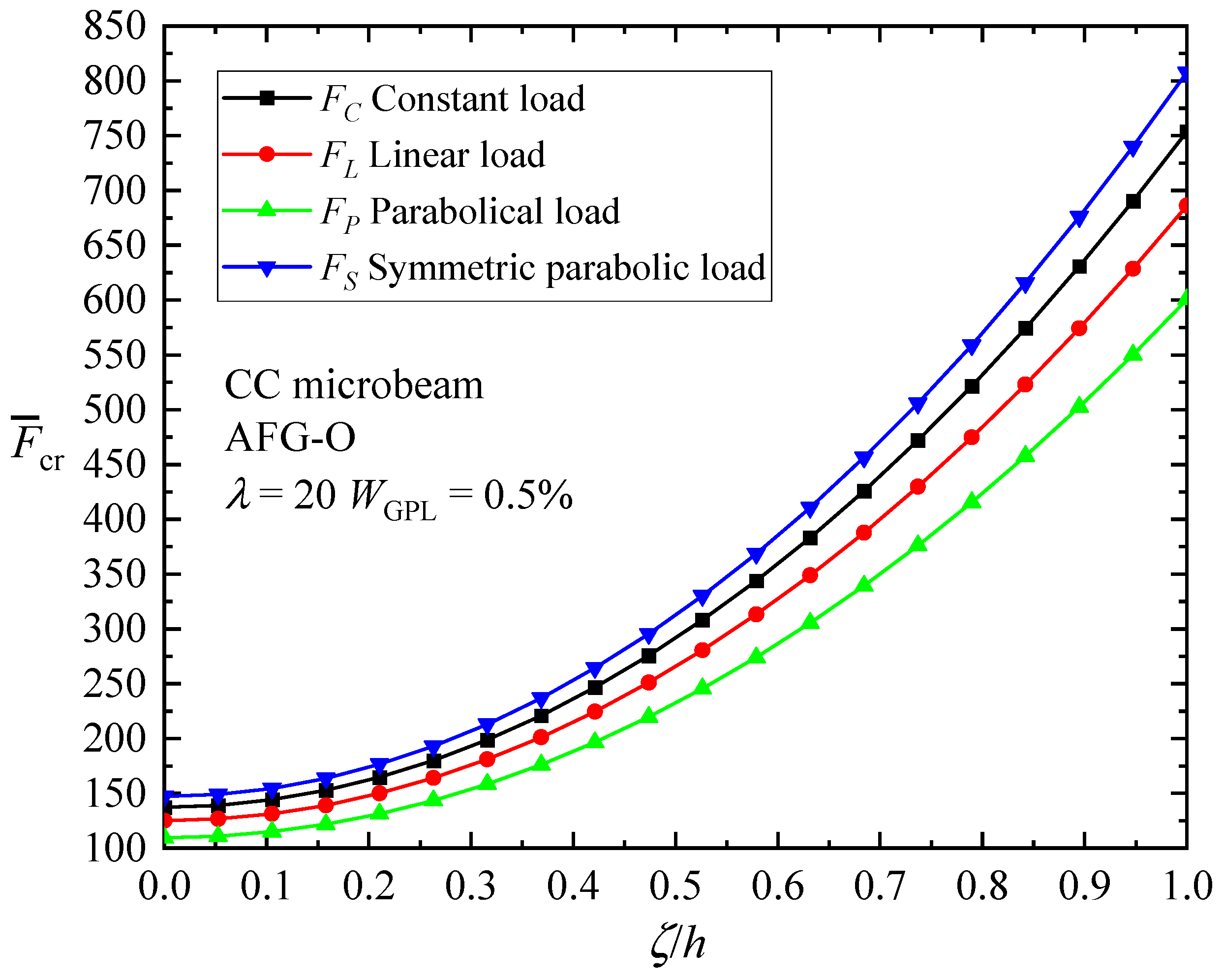
To further examine the size effect of AFG-GPLRC microbeams, the critical buckling loads with respect to material length scale parameter to thickness ratio
for CC microbeams are presented in
Figure 6. It is observed again that the material length scale enhances the buckling load, i.e., the intrinsic size dependence of the microbeam increases the bending stiffness, leading to increased values of critical buckling load, which confirms the stiffening effect of the length scale parameter.
Figure 7 plots the change in the critical buckling load of the AFG-O CC beam with respect to GPL geometry parameters, considering the change in the length-to-thickness ratio
and aspect ratio
of GPLs, as well as in the material length scale parameter
. The length of GPLs is held constant (
) in the figure. The buckling load firstly increases quickly as
increases, and then increases slowly for higher
ratios. It is concluded that nanofillers consisting of a smaller number of monolayer graphene sheets are expected to provide superior enhancing effects. In the meantime, it is seen that the increase in the width of GPLs leads to a rise in the value of the critical buckling load, which indicates that an increase in the area of the GPLs leads to a higher bending stiffness of the GPL-reinforced microbeams.
Figure 7 shows again the hardening effect of a micro-scaled beam due to the intrinsic material length.
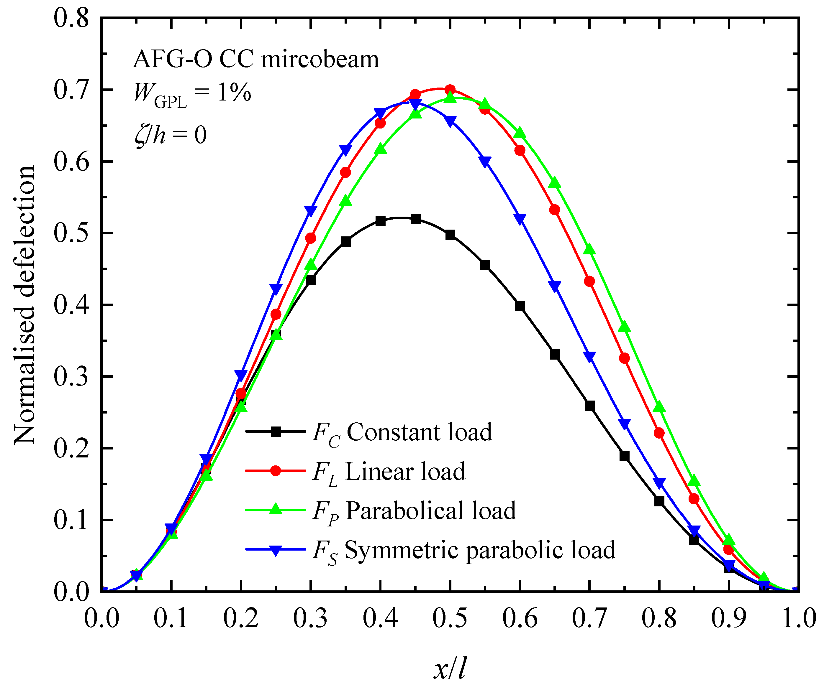
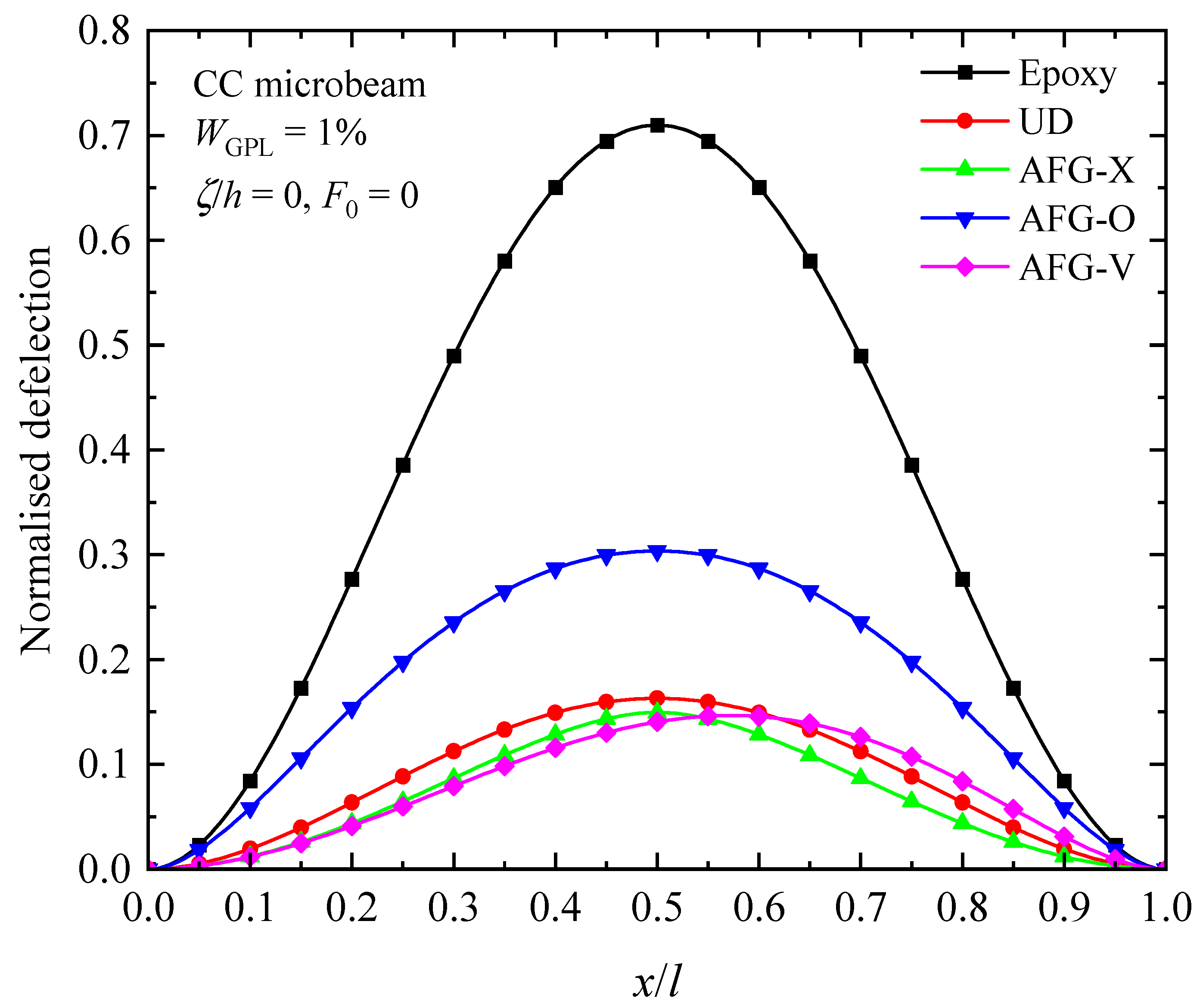
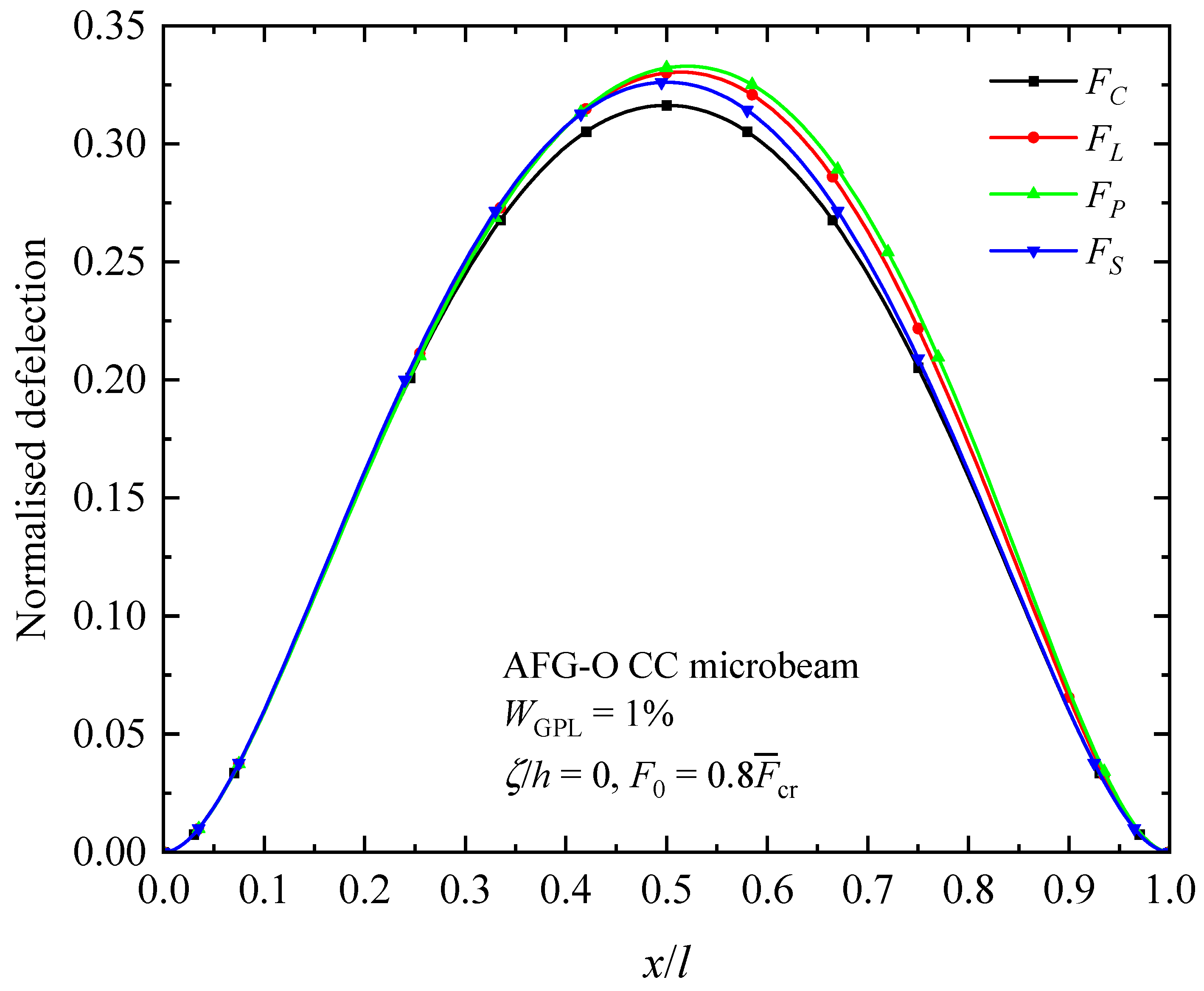
The influence of the nature of axially varying loads, axially graded dispersion of GPL nanofillers, and material intrinsic length scale on the fundamental buckling mode of the AFG-GPLRC CC microbeam are presented in
Figure 8,
Figure 9 and
Figure 10. From the figures, the buckling mode shapes of the microbeam under an axially applied load is asymmetric along the microbeam length in spite of symmetric boundary condition, symmetric GPL dispersion pattern and symmetric axially applied load. This can be interpreted due to the accumulation of the axially applied load. Meantime, it can be found that the distribution of axial load has a critical impact on the shape of buckling mode. For a given axially varying load, the buckling mode varies sensitively with axial distribution pattern of GPLs, as seen in
Figure 9. The GPL nano-reinforcements dispersed into epoxy matrix can observably improve the bending stiffness, and hence decreases the transverse deflection of AFG-GPLRC microbeams. For the given axially applied load, the AFG-X pattern holds the lowest peak value in the buckling mode. From
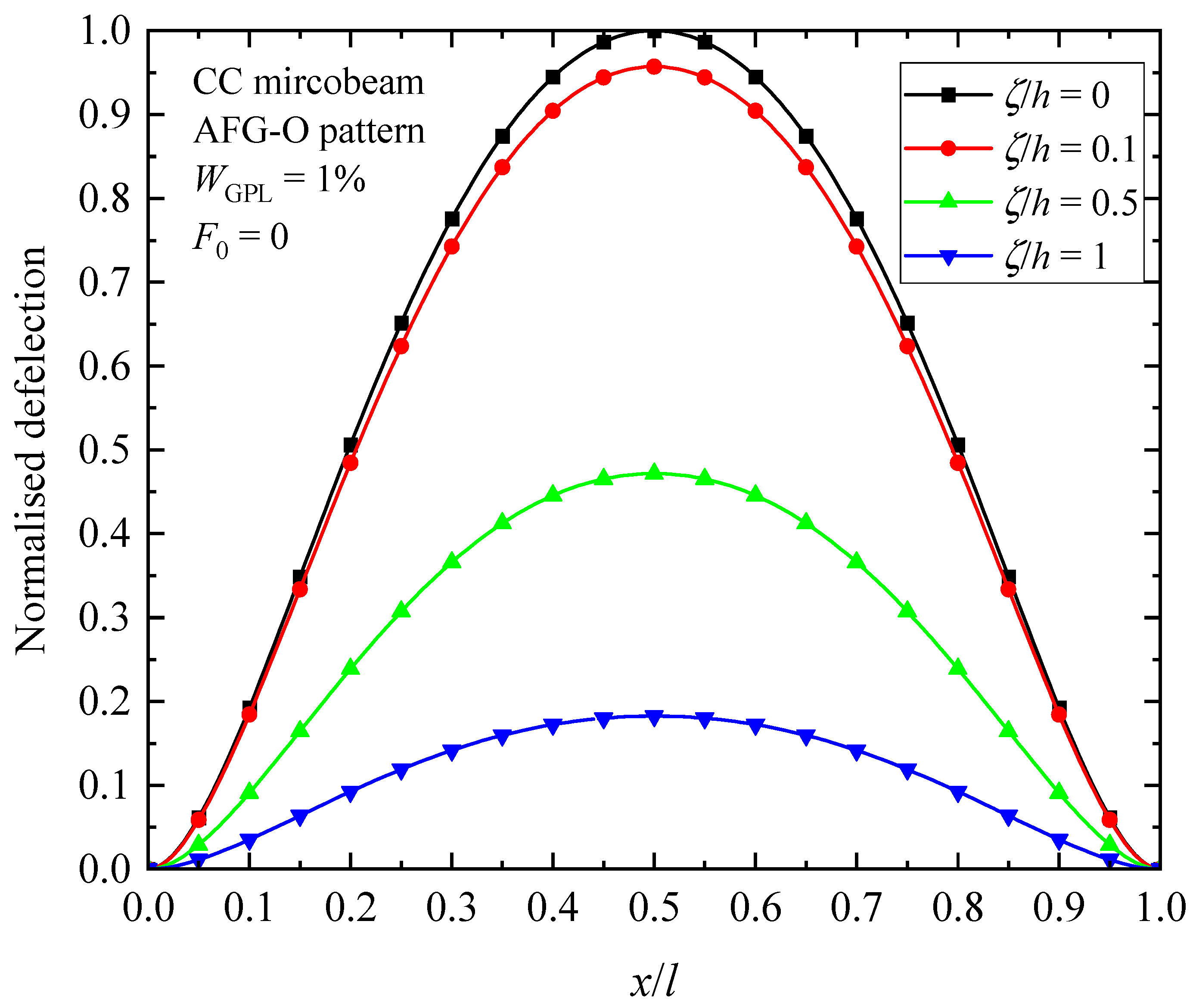
Figure 10, it demonstrates that the transverse deflection of AFG-GPLRC microbeams decreases with the increase in the material length scale parameter. This means that the microbeam having a larger stiffness when considering size effect has a less transverse displacement.
4.3. Free Vibration of AFG-GPLRC Microbeams
To investigate the vibration behaviors of AFG-GPLRC microbeams,
Table 10 lists the dimensionless fundamental frequency parameter
involved in axial GPL distribution patterns, boundary conditions, and the material length scale parameter to thickness ratios. It is seen from the table that the microbeam frequency rises significantly by adding GPL nano-reinforcements regardless of the GPL distribution pattern. As can be expected, the dispersion of GPLs leads to an increase in the microbeam bending stiffness. Similar tendencies found in the buckling study also apply to the reinforcing effects of GPL nanofillers on microbeam vibration performances, which rely on the boundary condition. It is important to note that the frequency increment is determined by both the boundary condition and the GPL distribution pattern. In other words, these two factors work together to influence the increase in frequency. This observation highlights the interplay between the microbeam boundary conditions and the GPL distribution pattern, both of which contribute to the changes in vibration frequencies. For instance, the AFG-O pattern exhibits a more pronounced enhancement in the vibration frequency of SS microbeams. On the other hand, the UD pattern yields the highest frequencies for microbeams with other boundary conditions. This suggests that the choice of GPL distribution pattern can have a significant impact on the vibration frequencies of microbeams, with different patterns showing varying degrees of enhancement depending on the specific boundary conditions. The size-dependent fundamental frequencies of the microbeams are also listed in
Table 13. It can be found that the frequencies increase monotonously as the material length scale parameter
ζ increases. It is due to this that the increasing
ζ yields a more powerful small-scale effect that makes the microbeams stiffer.
Table 10.
Fundamental frequency of the AFG-GPLRC microbeam without considering axial load.
Table 10.
Fundamental frequency of the AFG-GPLRC microbeam without considering axial load.
| B.C. | ζ/h | Epoxy | UD | AFG-X | AFG-O | AFG-V |
|---|
| SS | 0 | 9.8696 | 20.6166 | 15.2374 | 22.6759 | 19.6099 |
| 0.1 | 10.0881 | 21.0737 | 15.5750 | 23.1788 | 20.0446 |
| 0.5 | 14.3683 | 30.0243 | 22.1860 | 33.0263 | 28.5569 |
| 1.0 | 23.0991 | 48.2773 | 35.6698 | 53.1070 | 45.9167 |
| CC | 0 | 22.3733 | 46.7355 | 45.9273 | 38.9470 | 42.3031 |
| 0.1 | 22.8687 | 47.7716 | 46.9459 | 39.8104 | 43.2410 |
| 0.5 | 32.5714 | 68.0616 | 66.8905 | 56.7173 | 61.6064 |
| 1.0 | 52.3631 | 109.4392 | 107.5613 | 91.1966 | 99.0593 |
| CF | 0 | 3.5160 | 7.3446 | 7.2080 | 5.6277 | 8.7530 |
| 0.1 | 3.5939 | 7.5074 | 7.3678 | 5.7524 | 8.9472 |
| 0.5 | 5.1187 | 10.6960 | 10.4969 | 8.1942 | 12.7495 |
| 1.0 | 8.2290 | 17.1986 | 16.8782 | 13.1745 | 20.5026 |
| CS | 0 | 15.4182 | 32.2070 | 29.5869 | 29.9310 | 27.6900 |
| 0.1 | 15.7596 | 32.9211 | 30.2429 | 30.5946 | 28.3038 |
| 0.5 | 22.4461 | 46.9036 | 43.0883 | 43.5895 | 40.3227 |
| 1.0 | 36.0852 | 75.4183 | 69.2839 | 70.0900 | 64.8343 |
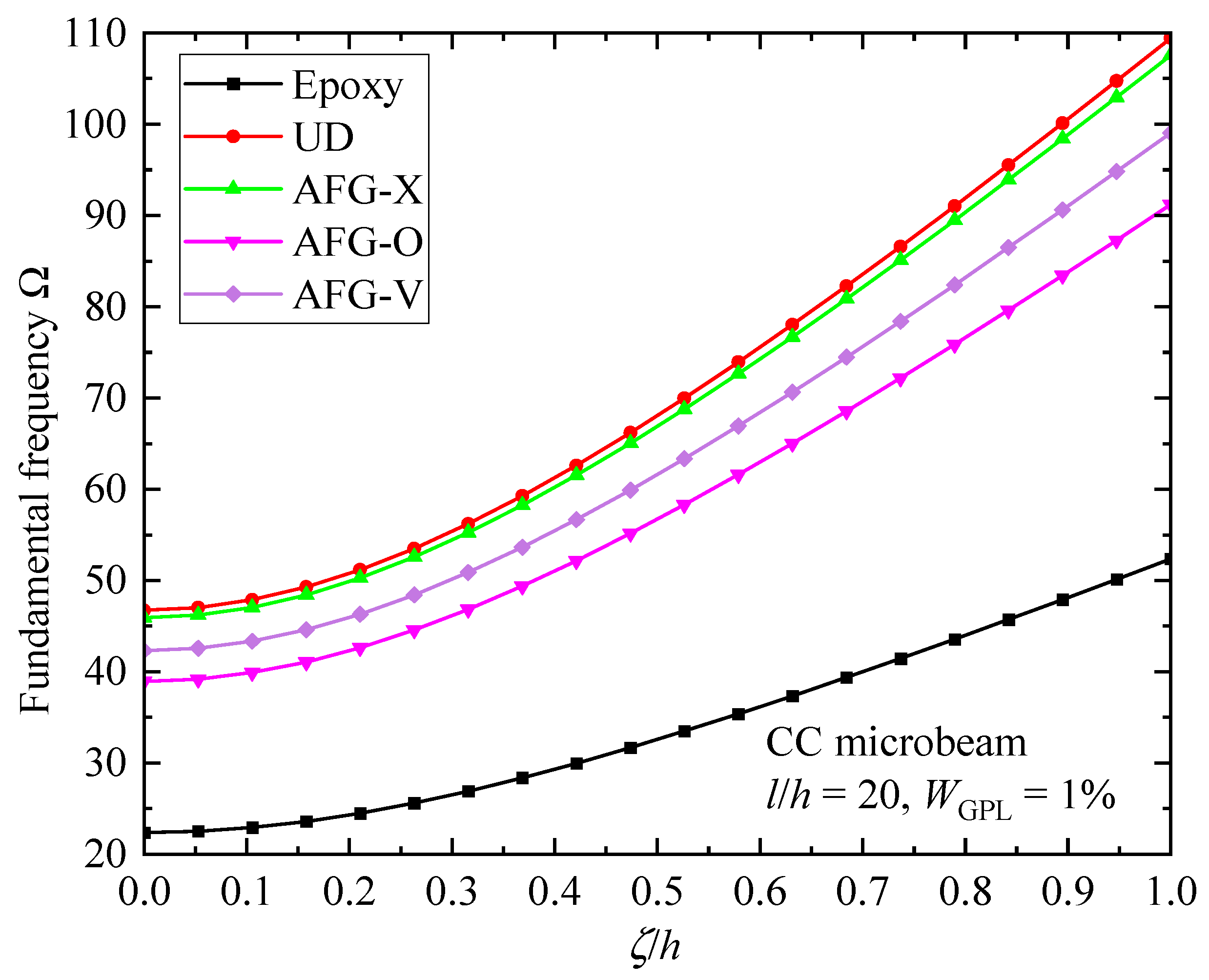
To further illustrate the impacts of the GPL enhancement effect and micro-size effect,
Figure 11 depicts the fundamental frequency parameter
of the AFG-GPLRC CC microbeams against the material length scale parameter. As can be observed, as the parameter
ζ increases, the fundamental frequency consistently and monotonously increases. Compared with pure epoxy, the fundamental frequency of the AFG-GPLRC microbeam exhibits a sharper increase, which indicates that the GPL incremental effect on the fundamental frequency is strengthened by size effects. However, the incremental effect depends on the GPL distribution pattern. For the CC microbeams, the UD pattern produces the highest fundamental frequency, followed by AFG-X, AFG-V, and AFG-O patterns. It should, again, be pointed out that the enhancement of GPL nanofillers is determined by both the GPL distribution patterns and boundary conditions.
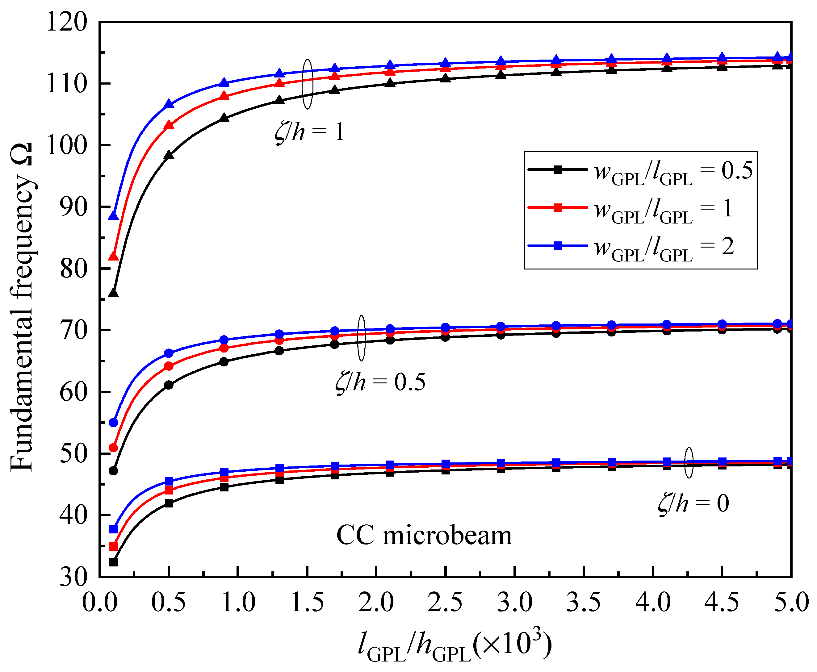
Figure 12 studies the fundamental frequency variation versus the size and geometry of GPLs for the UD CC microbeams against different material length scale parameters. A constant GPL length
lGPL = 2.5 μm is kept during analysis. As shown in
Figure 12, the frequency first increases very fast, and then slowly increases for larger
lGPL/
hGPL. It can be noted here that the GPL nano-reinforcements contain fewer graphene layers for a larger value of
lGPL/
hGPL, and hence improve the microbeam frequencies more effectively. It is also seen that the microbeams reinforced by GPLs with larger
wGPL/
lGPL produce larger frequencies. This means that the larger surface area of GPL nano-reinforcements provided a more superior reinforcement effect.
Table 11,
Table 12,
Table 13 and
Table 14 reveal the influence of axial variations in the GPL distribution pattern and applied load on the fundamental frequency
of the AFG-GPLRC microbeam, respectively. It is noted the material length scale effect is not considered in these tables, i.e.,
, and
denotes the buckling load of a pure epoxy microbeam. To maintain consistency with the previous discussion, the positive values of
denote compressive loads and the negative ones represent tensional loads. From the tables, the dimensionless natural frequency descends with an increase in axial compression force. On the other hand, it rises with an enlarging of the axial tension force. These trends highlight the influence of axially applied loads on the vibration of microbeams and provide insights into the relationship between axially applied loads and natural frequencies. However, the synergetic dependences of the fundamental frequency on the GPL distribution pattern, axially applied load, and boundary condition are quite complex. It has been observed that the AFG-O pattern consistently yields the highest frequency for all given axially applied loads. In contrast, the UD microbeam gives the largest value of frequency for CC and CS boundary conditions, while AFG-V is the most effective in enhancing the vibration frequency of CF microbeams. For a given GPL distribution pattern and average value of applied load
, the type of axially applied load can also critically influence the vibration performance. For instance, the AFG-O SS microbeams under a symmetric parabolic load
hold the highest natural frequency regardless of compressive or tensional load. However, the AFG-V CF microbeam under a parabolical load
and constant load
yields the highest ones for tensional and compressive loads, respectively.
Table 11.
Dimensionless fundamental frequency for the AFG-GPLRC SS microbeam ().
Table 11.
Dimensionless fundamental frequency for the AFG-GPLRC SS microbeam ().
| AVLs | | Epoxy | UD | AFG-X | AFG-O | AFG-V |
|---|
| FC | | 12.5834 | 22.0467 | 17.1536 | 23.9985 | 21.1403 |
| 10.6133 | 20.9832 | 15.7385 | 23.0137 | 20.0037 |
| 9.0651 | 20.2433 | 14.7192 | 22.3329 | 19.2078 |
| 6.0396 | 19.0796 | 13.0410 | 21.2706 | 17.9466 |
| FL | | 12.5092 | 22.0361 | 17.1426 | 23.9839 | 21.3487 |
| 10.6073 | 20.9825 | 15.7377 | 23.0127 | 20.0633 |
| 9.0577 | 20.2425 | 14.7184 | 22.3319 | 19.1422 |
| 5.8383 | 19.0666 | 13.0257 | 21.2529 | 17.6418 |
| FP | | 12.7911 | 22.2372 | 17.3180 | 24.2204 | 21.6802 |
| 10.7110 | 21.0382 | 15.7883 | 23.0784 | 20.1579 |
| 8.9153 | 20.1827 | 14.6620 | 22.2612 | 19.0381 |
| 4.6089 | 18.7977 | 12.7545 | 20.9349 | 17.1521 |
| FS | | 11.7775 | 21.6072 | 16.7620 | 23.4757 | 20.6275 |
| 10.3850 | 20.8693 | 15.6343 | 22.8789 | 19.8699 |
| 9.3214 | 20.3603 | 14.8286 | 22.4706 | 19.3458 |
| 7.4025 | 19.5682 | 13.5194 | 21.8411 | 18.5274 |
Table 12.
Dimensionless fundamental frequency for the AFG-GPLRC CC microbeam ().
Table 12.
Dimensionless fundamental frequency for the AFG-GPLRC CC microbeam ().
| AVLs | | Epoxy | UD | AFG-X | AFG-O | AFG-V |
|---|
| FC | | 29.1182 | 50.3587 | 50.1791 | 42.7745 | 46.3175 |
| 24.2563 | 47.6698 | 47.0344 | 39.9395 | 43.3458 |
| 20.2974 | 45.7801 | 44.7869 | 37.9276 | 41.2308 |
| 11.8556 | 42.7733 | 41.1347 | 34.6842 | 37.8099 |
| FL | | 28.9486 | 50.3328 | 50.1586 | 42.7218 | 46.9863 |
| 24.2417 | 47.6680 | 47.0330 | 39.9358 | 43.5401 |
| 20.2780 | 45.7782 | 44.7854 | 37.9236 | 41.0141 |
| 11.1889 | 42.7396 | 41.1075 | 34.6091 | 36.7696 |
| FP | | 28.7431 | 50.2761 | 49.8635 | 42.9003 | 47.3501 |
| 24.2113 | 47.6575 | 46.9548 | 39.9955 | 43.6537 |
| 20.2810 | 45.7857 | 44.8671 | 37.8511 | 40.8807 |
| 10.6588 | 42.7482 | 41.4612 | 34.2189 | 36.0722 |
| FS | | 28.9878 | 50.6885 | 50.6827 | 42.2585 | 46.1296 |
| 24.2701 | 47.6850 | 47.1846 | 39.8086 | 43.3033 |
| 20.2281 | 45.7590 | 44.6167 | 38.0601 | 41.2699 |
| 10.6099 | 42.6462 | 40.3016 | 35.2266 | 37.9410 |
Table 13.
Dimensionless fundamental frequency for the AFG-GPLRC CF microbeam ().
Table 13.
Dimensionless fundamental frequency for the AFG-GPLRC CF microbeam ().
| AVLs | | Epoxy | UD | AFG-X | AFG-O | AFG-V |
|---|
| FC | | 4.2112 | 7.7101 | 7.6807 | 6.0174 | 9.0995 |
| 3.7061 | 7.4381 | 7.3301 | 5.7280 | 8.8415 |
| 3.3117 | 7.2495 | 7.0829 | 5.5253 | 8.6631 |
| 2.5763 | 6.9541 | 6.6888 | 5.2038 | 8.3850 |
| FL | | 4.3737 | 7.8196 | 7.8649 | 6.0920 | 9.2236 |
| 3.7627 | 7.4680 | 7.3812 | 5.7490 | 8.8752 |
| 3.2383 | 7.2178 | 7.0278 | 5.5026 | 8.6274 |
| 2.0713 | 6.8150 | 6.4395 | 5.1006 | 8.2284 |
| FP | | 4.4156 | 7.8617 | 7.9465 | 6.1139 | 9.2781 |
| 3.7842 | 7.4803 | 7.4055 | 5.7560 | 8.8913 |
| 3.2035 | 7.2040 | 7.0004 | 5.4942 | 8.6095 |
| 1.7028 | 6.7496 | 6.3059 | 5.0579 | 8.1436 |
| FS | | 4.2511 | 7.7287 | 7.6887 | 6.0421 | 9.1046 |
| 3.7158 | 7.4427 | 7.3318 | 5.7344 | 8.8425 |
| 3.3023 | 7.2449 | 7.0815 | 5.5188 | 8.6624 |
| 2.5404 | 6.9360 | 6.6848 | 5.1770 | 8.3837 |
Table 14.
Dimensionless fundamental frequency for the AFG-GPLRC CS microbeam ().
Table 14.
Dimensionless fundamental frequency for the AFG-GPLRC CS microbeam ().
| AVLs | | Epoxy | UD | AFG-X | AFG-O | AFG-V |
|---|
| FC | | 18.6890 | 33.9065 | 31.5551 | 31.6508 | 33.7410 |
| 16.3024 | 32.6408 | 30.0920 | 30.3707 | 32.3107 |
| 14.4760 | 31.7669 | 29.0723 | 29.4842 | 31.3144 |
| 11.1458 | 30.4055 | 27.4662 | 28.0985 | 29.7461 |
| FL | | 19.3101 | 34.3092 | 31.9563 | 32.0265 | 34.4657 |
| 16.5106 | 32.7496 | 30.2006 | 30.4751 | 32.5097 |
| 14.2120 | 31.6520 | 28.9573 | 29.3719 | 31.1015 |
| 9.4039 | 29.9047 | 26.9615 | 27.5933 | 28.7957 |
| FP | | 19.7778 | 34.6448 | 32.2076 | 32.4312 | 35.0244 |
| 16.6835 | 32.8427 | 30.2712 | 30.5901 | 32.6702 |
| 13.9726 | 31.5517 | 28.8806 | 29.2458 | 30.9239 |
| 7.3098 | 29.4526 | 26.6104 | 27.0079 | 27.9525 |
| FS | | 18.0867 | 33.5910 | 31.4111 | 31.1437 | 33.2416 |
| 16.1384 | 32.5600 | 30.0565 | 30.2398 | 32.1809 |
| 14.6534 | 31.8492 | 29.1075 | 29.6181 | 31.4480 |
| 11.9970 | 30.7445 | 27.6048 | 28.6542 | 30.3061 |
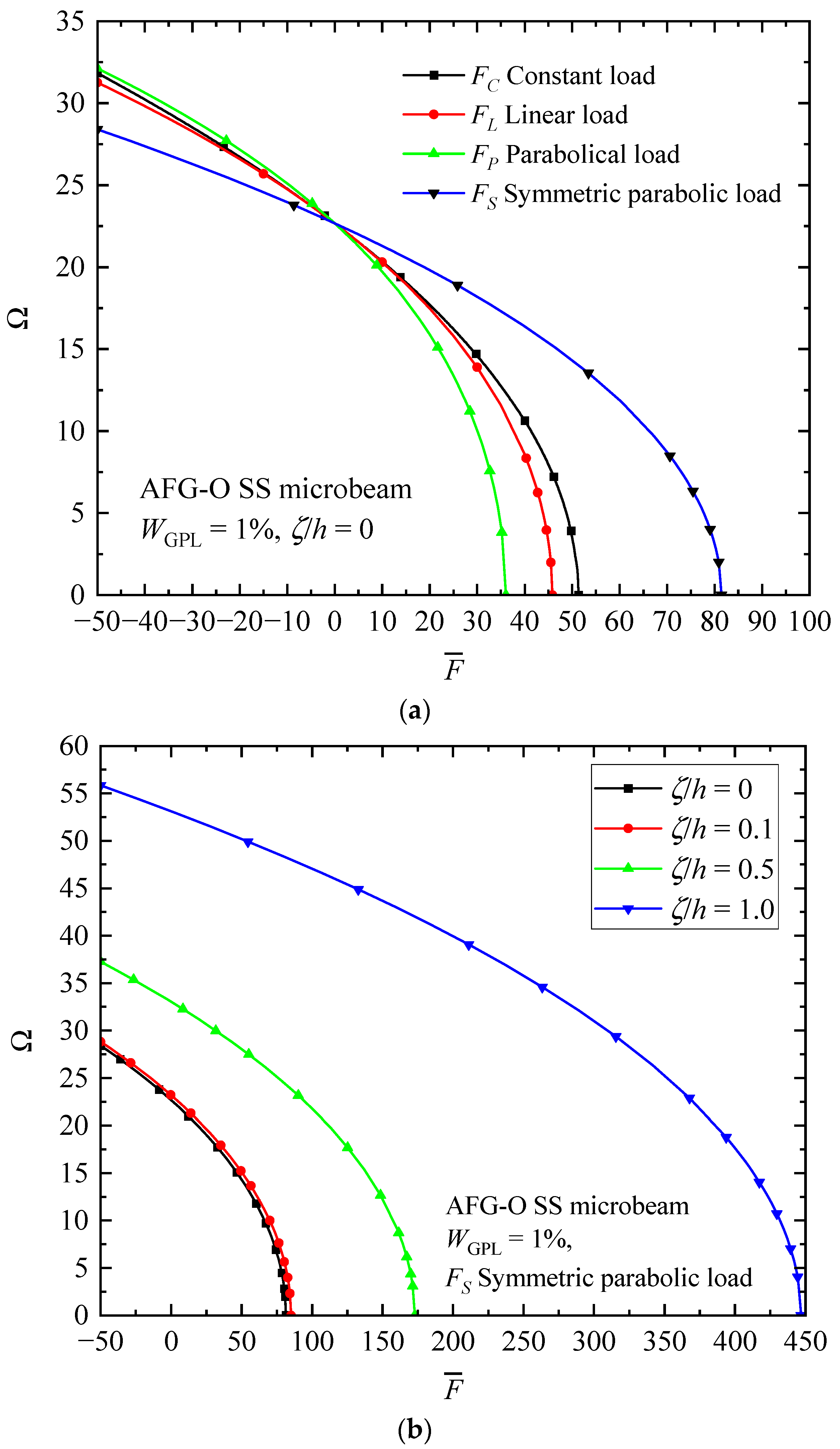
Figure 13 reveals the relationship between an axially applied load
and the fundamental frequency
of AFG-GPLRC microbeams. For the sake of brevity, only the simply supported AFG-O microbeam is analyzed under different types of axially variable loads and/or material length scale parameters. It is seen that the fundamental frequency decreases sharply with the promotion of the compressive load (
). The fundamental frequency tends to approach zero when the axial load applied reaches the buckling load
. In contrast, the frequency raises with tension loading (
). Therefore, the compressive axial load decreases the beam stiffness, while the tensional load imposes an opposite influence. From the figure, it is again certified that the intrinsic size effect could dramatically promote the stiffness of the size-dependent microbeams, which, in turn, increases the vibration frequency and critical buckling load.
Figure 14,
Figure 15 and
Figure 16 illustrate the changes in the shape of the fundamental vibration mode with respect to the axial GPL distribution, axially applied load, and material length scale parameters, respectively. Due to the comparability, only the CC microbeam is considered. It should be noticed that the axially graded distribution of GPL nanofillers plays a critical role in deciding the deflection of the AFG-GPLRC microbeams. The dispersion of GPLs increases the stiffness of the microbeam powerfully, and hence reduces the deformation. From
Figure 12, it is seen that the deflection is symmetric except in the case of AFG-V, where the axial load is without consideration. However,
Figure 13 shows that the vibration modes of microbeams with AVLs are asymmetric, even with a symmetric GPL distribution and boundary condition. This is because of the accumulation of axially applied loads like the buckling mode.
Figure 14 demonstrates again that the size effect could promote the bending stiffness of the microbeams and decrease the peak of the vibration mode shape.


