
Research Progress on Surface Damage and Protection Strategies of Armature–Rail Friction Pair Materials for Electromagnetic Rail Launch

Abstract
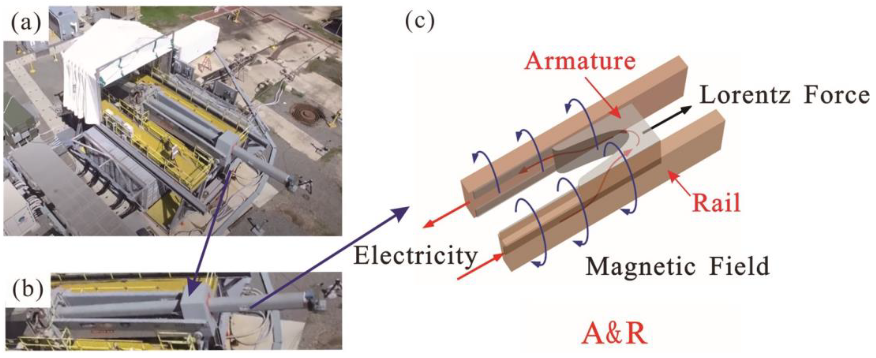
1. Introduction
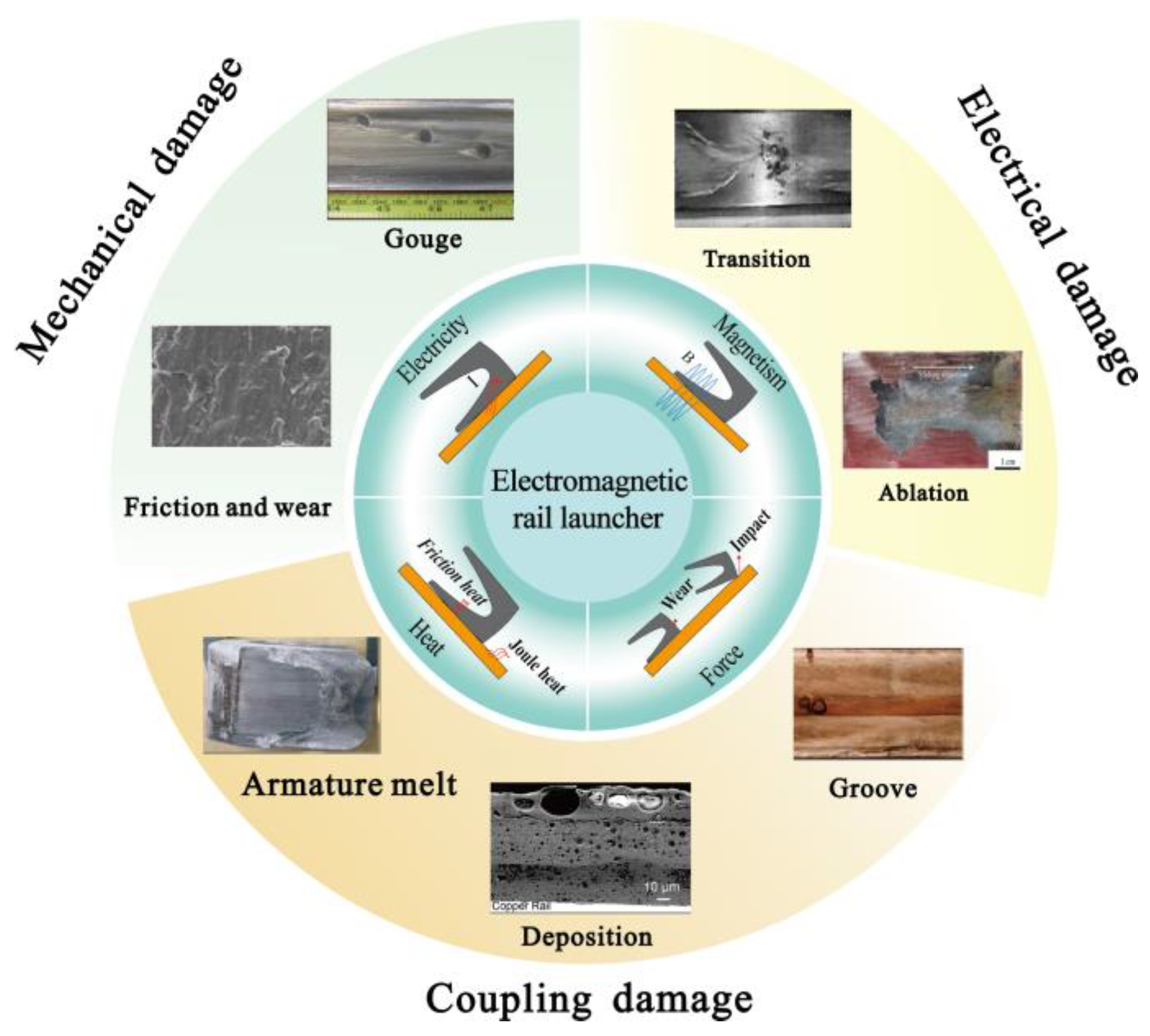
2. Surface Damage of A&R
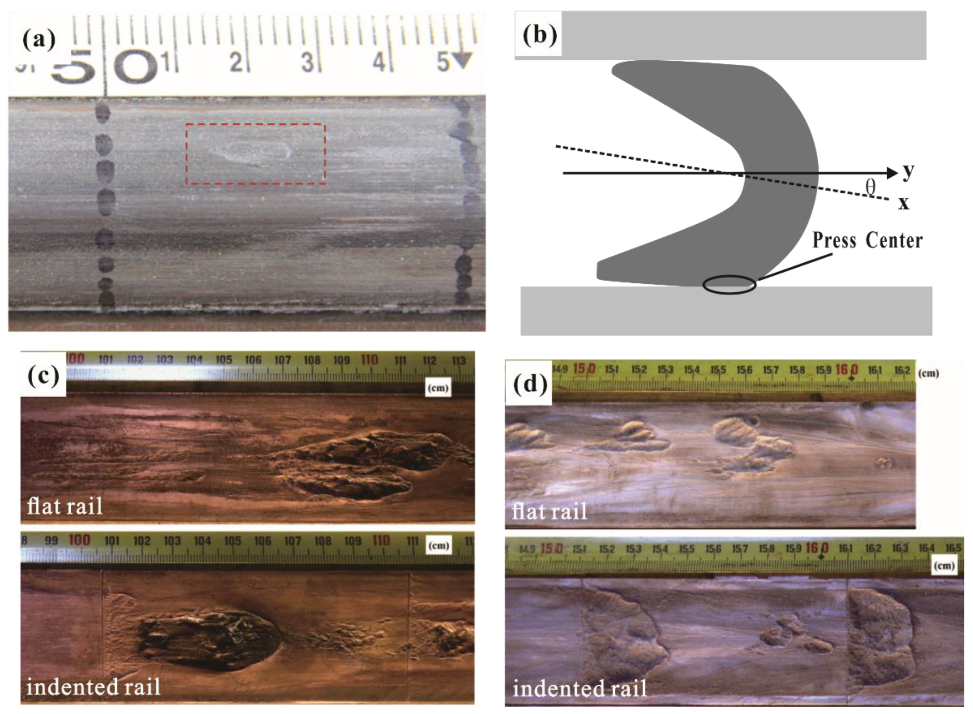
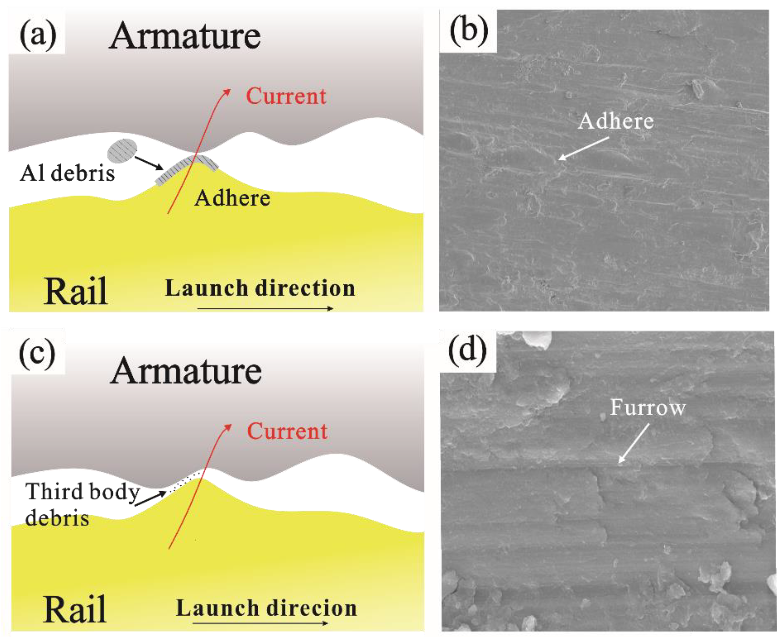
2.1. Mechanical Damage
2.2. Electrical Damage
2.3. Coupling Damage
2.4. Summary of Surface Damage
3. Protection Strategies for Surface Damage
3.1. Material Improvement
3.2. Surface Treatment Technology
3.2.1. Structural Coating for Wear Resistance
3.2.2. Functional Coating for Ablation and Melt Resistance
3.3. Summary of Protection Strategies for Surface Damage
4. Conclusions and Outlook
- (1)
- In terms of material, more severe environments result in higher requirements for the A&R materials. High strength and conductivity and wear resistance are the goals of A&R materials. The research on new material systems and combined treatment technology are the direction of the future development of A&R materials.
- (2)
- In terms of coating and preparation technology, large-area uniform coating preparation technology and new materials with high conductivity, wear resistance, ablative resistance, and strong binding forces should be explored to further optimize the quality of the coating.
- (3)
- In terms of the friction pair system, most current research has been aimed at separating the armature from the rail, and different pairing mechanisms should be considered during material development.
- (4)
- In terms of material testing, due to the relatively large cost of electromagnetic emissions, it is necessary to develop material-equivalent test methods to evaluate whether new materials meet actual emission requirements.
- (5)
- In terms of the mechanism of wear and ablation, the understanding of conductive wear resistance and ablation resistance should be deepened. Research on the mechanism of current-carrying tribology and the arc ablation under extreme conditions is highly required.
Author Contributions
Funding
Institutional Review Board Statement
Informed Consent Statement
Data Availability Statement
Conflicts of Interest
References
- Ma, W.M.; Lu, J.Y. Thinking and Study of Electromagnetic Launch Technology. IEEE Trans. Plasma Sci. 2017, 45, 1071–1077. [Google Scholar] [CrossRef]
- Fair, H.D. The science and technology of electric launch. IEEE Trans. Magn. 2001, 37, 25–32. [Google Scholar] [CrossRef]
- Ma, W.; Lu, J.; Liu, Y. Research progress of electromagnetic launch technology. IEEE Trans. Plasma Sci. 2019, 47, 2197–2205. [Google Scholar] [CrossRef]
- Gao, X.; Liu, F.; Feng, Y.; Zhang, H.; Zhan, Z. Wear Characteristics of Rail–Armature Under the Action of Interference Fit and Lorentz Force. IEEE Trans. Plasma Sci. 2020, 48, 2261–2265. [Google Scholar] [CrossRef]
- Praneeth, S.N.; Singh, B. Finite Element-Boundary Element Method Based Simulations of Electromagnetic Railgun in Augmented Configurations. IEEE J. Multiscale Multiphys. Comput. Tech. 2022, 7, 320–327. [Google Scholar] [CrossRef]
- Xu, W.D.; Yuan, W.Q.; Sun, Y.H.; Yan, P.; Li, J. Research on the Sliding Electrical Contact of the Rapid Fire Railgun. IEEE Trans. Plasma Sci. 2013, 41, 1542–1546. [Google Scholar]
- Motes, D.; Keena, J.; Womack, K.; Stefani, F.; Crawford, M. Thermal Analysis of High-Energy Railgun Tests. IEEE Trans. Plasma Sci. 2012, 40, 124–130. [Google Scholar] [CrossRef]
- Bayati, M.S.; Keshtkar, A.; Keshtkar, A. Thermal computation in railgun by hybrid time domain technique 3-D-FEM-IEM. IEEE Trans. Plasma Sci. 2010, 39, 18–21. [Google Scholar] [CrossRef]
- Xie, H.B.; Yang, H.Y.; Yu, J.; Gao, M.Y.; Shou, J.D.; Fang, Y.T.; Liu, J.B.; Wang, H.T. Research progress on advanced rail materials for electromagnetic railgun technology. Def. Technol. 2021, 17, 429–439. [Google Scholar] [CrossRef]
- Dutta, I.; Delaney, L.; Cleveland, B.; Persad, C. Electric Current Induced Liquid Al Deposition, Reaction and Flow on Cu Rails at Rail-Armature Contacts in Railguns. In Proceedings of the 2008 14th Symposium on Electromagnetic Launch Technology, Victoria, BC, Canada, 10–13 June 2008. [Google Scholar]
- Stefani, F.; Merrill, R. Experiments to measure melt-wave erosion in railgun armatures. IEEE Trans. Magn. 2003, 39, 188–192. [Google Scholar] [CrossRef]
- Stonkus, R.; Račkauskas, J.; Schneider, M.; Kačianauskas, R. Structural mechanics of railguns with open barrels and elastic supports: The influence of multishot operation. IEEE Trans. Plasma Sci. 2015, 43, 1510–1515. [Google Scholar] [CrossRef]
- Wild, B.; Schuppler, C.; Alouahabi, F.; Schneider, M.; Hoffman, R. The influence of the rail material on the multishot performance of the rapid fire railgun. IEEE Trans. Plasma Sci. 2015, 43, 2095–2099. [Google Scholar] [CrossRef]
- Gnegy-Davidson, C.; Wetz, D.; Wong, D.; Horton, D. The effect of salt-water corrosion on copper alloy rail claddings in a small railgun. IEEE Trans. Plasma Sci. 2017, 45, 1419–1428. [Google Scholar] [CrossRef]
- Watt, T.J.; Clay, C.E.; Bassett, P.M.; Bourell, D.L. The effect of surface indentations on gouging in railguns. Wear 2014, 310, 41–50. [Google Scholar] [CrossRef]
- Barber, J.P.; Bauer, D.P. Contact phenomena at hypervelocities. Wear 1982, 78, 163–169. [Google Scholar] [CrossRef]
- Persad, C.; Prabhu, G.; White, G.; Yeoh, A.; Eliezer, Z. Characterization of hypervelocity gouge craters in rail conductors. IEEE Trans. Magn. 1997, 33, 401–405. [Google Scholar] [CrossRef]
- Lin, Q. Armature dynamics—An aspect of rail gouging mechanisms in electromagnetic railgun. Int. J. Appl. Electromagn. Mech. 2022, 70, 33–54. [Google Scholar] [CrossRef]
- Wu, J.G.; Tang, B.; Lin, Q.H.; Li, H.Y.; Li, B.M. 3D numerical simulation and analysis of railgun gouging mechanism. Def. Technol. 2016, 12, 90–95. [Google Scholar] [CrossRef]
- Brown, L.; Xu, D.; Ravi-Chandar, K.; Satapathy, S. Coefficient of Friction Measurement in the Presence of High Current Density. IEEE Trans. Magn. 2007, 43, 334–337. [Google Scholar] [CrossRef]
- Stefani, F.; Parker, J.V. Experiments to measure wear in aluminum armatures. IEEE Trans. Magn. 1999, 35, 100–106. [Google Scholar] [CrossRef]
- Wu, J.; Wan, G.; Cheng, N.; Li, L.; Li, B. Research on Armature’s Wearing and Dynamic Interior Ballistic of A Railgun. IEEE Trans. Plasma Sci. 2017, 45, 1202–1207. [Google Scholar] [CrossRef]
- Ren, S.; Feng, G.; Liu, S. Study on Wear of Electromagnetic Railgun. IEEE Access 2022, 10, 100955–100963. [Google Scholar] [CrossRef]
- James, T.E.; James, D.C. Contact pressure distribution and transition in solid armatures [EM launchers]. IEEE Trans. Magn. 2001, 37, 81–85. [Google Scholar] [CrossRef]
- Barber, J.; Bauer, D.; Jamison, K.; Parker, J.; Stefani, F.; Zielinski, A. A survey of armature transition mechanisms. IEEE Trans. Magn. 2003, 39, 47–51. [Google Scholar] [CrossRef]
- Woods, L.C. The current melt-wave model. IEEE Trans. Magn. 1997, 33, 152–156. [Google Scholar] [CrossRef]
- Stefani, F.; Merrill, R.; Watt, T. Numerical modeling of melt-wave erosion in two-dimensional block armatures. IEEE Trans. Magn. 2005, 41, 437–441. [Google Scholar] [CrossRef]
- Sun, J.; Cheng, J.; Wang, Q.; Xiong, L.; Cong, Y.; Wang, Y. Numerical Simulation of Melt-Wave Erosion in 2-D Solid Armature. IEEE Trans. Plasma Sci. 2022, 50, 1032–1039. [Google Scholar] [CrossRef]
- Stefani, F.; Levinson, S. Electrodynamic Transition in Solid Armature Railguns. IEEE Trans. Magn. 2001, 37, 101–105. [Google Scholar] [CrossRef]
- Robert, M.; Stefani, F.; Watt, T. Magnetic Repulsive Forces on Armature Contacts. IEEE Trans. Magn. 2007, 43, 384–387. [Google Scholar]
- Satapathy, S.; Vanicek, H. Down-Slope Contact Transition in Railguns. IEEE Trans. Magn. 2006, 43, 402–407. [Google Scholar] [CrossRef]
- Tang, B.; Xu, Y.; Lin, Q.; Li, B. Synergy of melt-wave and electromagnetic force on the transition mechanism in electromagnetic launch. IEEE Trans. Plasma Sci. 2017, 45, 1361–1367. [Google Scholar] [CrossRef]
- Zhang, Q.; Li, J.; Li, S.; Liu, P.; Jin, L.; Liu, G. Causes of damage at electromagnetic railgun’s initial position and corresponding improvement measures. IEEE Trans. Plasma Sci. 2019, 47, 4184–4188. [Google Scholar] [CrossRef]
- Barber, J.P.; Dreizin, Y.A. Model of contact transitioning with “realistic” armature-rail interface. IEEE Trans. Magn. 1995, 31, 96–100. [Google Scholar] [CrossRef]
- Li, S.; Li, J.; Wang, X.; Zhang, Q.; Liu, P. Research on Segmentation Evaluation Model of Sliding Electrical Contact Performance of Electromagnetic Railgun. IEEE Trans. Plasma Sci. 2019, 47, 2424–2430. [Google Scholar] [CrossRef]
- Che, Y.; Yuan, W.; Yuan, W.; Wang, Z.; Hao, W.; Zhao, Y.; Yan, P. Analysis of Sliding Contact of Armature Inside the Vertical Curved Rails in Electromagnetic Railgun. IEEE Trans. Plasma Sci. 2023, 51, 1357–1363. [Google Scholar] [CrossRef]
- Cai, X.; Tan, S.; Lu, J.; Zhang, X.; Li, B.; Zhang, J. Simulation and analysis of muzzle arc of electromagnetic rail launch. IEEE Trans. Plasma Sci. 2021, 49, 3016–3021. [Google Scholar] [CrossRef]
- Xia, S.; Hu, Y.; Chen, L.; He, J.; Yuan, Z.; He, H.; Yan, P.; Li, J. Experimental Studies on Melt Erosion at Rail-Armature Contact of Rail Launcher in Current Range of 10–20 kA/mm. IEEE Trans. Plasma Sci. 2017, 45, 1667–1672. [Google Scholar] [CrossRef]
- Zhang, H.; Gao, X.; Huang, L.; Lu, T.; Liu, F. Mechanism of Butterfly-Shaped Failure Interface Between Armature and Rails. IEEE Trans. Plasma Sci. 2020, 48, 2280–2286. [Google Scholar] [CrossRef]
- Li, B.; Ma, W.; Lu, J.; Tan, S.; Zhang, Y.; Cai, X. Effects of Supply Current and Armature Structure on Melting Characteristics of Armature Surface in Sliding Electric Contact. IEEE Trans. Plasma Sci. 2019, 47, 721–728. [Google Scholar] [CrossRef]
- Li, C.; Chen, L.; Wang, Z.; Ruan, J.; Xia, S. Influence of Armature Movement Velocity on the Magnetic Field Distribution and Current Density Distribution in Railgun. IEEE Trans. Plasma Sci. 2020, 48, 2308–2315. [Google Scholar] [CrossRef]
- Huang, W.; Yang, L.; Shi, G.; Liu, X.; Chen, Z.; Tian, K. Surface microstructure evolution of CuCrZr alloy under current-carrying friction. Chin. J. Rare Metals 2020, 44, 687–696. [Google Scholar]
- Persad, C.; Castro, Z. Railgun tribology: Characterization and control of multishot wear debris. IEEE Trans. Magn. 2006, 43, 173–177. [Google Scholar] [CrossRef]
- Meger, R.A.; Cooper, K.; Jones, H.; Neri, J.; Qadri, S.; Singer, I.L.; Sprague, J.; Wahl, K.J. Analysis of rail surfaces from a multishot railgun. In Proceedings of the Symposium on Electromagnetic Launch Technology, Snowbird, UT, USA, 25–28 May 2004. [Google Scholar]
- Cooper, K.P.; Jones, H.N.; Meger, R.A. Analysis of railgun barrel material. IEEE Trans. Magn. 2006, 43, 120–125. [Google Scholar] [CrossRef]
- Machado, B.; Murr, L.; Martinez, E.; Gaytan, S.; Satapathy, S. Materials characterization of railgun erosion phenomena. Mater. Sci. Eng. A 2011, 528, 7552–7559. [Google Scholar] [CrossRef]
- Watt, T.; Stefani, F.; Crawford, M.; Mark, H.; Parker, J. Investigation of Damage to Solid-Armature Railguns at Startup. IEEE Trans. Magn. 2007, 43, 214–218. [Google Scholar] [CrossRef]
- Zielinski, A.; Watt, T.; Motes, D. Disrupting armature ejecta and its effects on rail damage in solid-armature railguns. IEEE Trans. Plasma Sci. 2011, 39, 941–946. [Google Scholar] [CrossRef]
- Gee, R.M.; Persad, C. The response of different copper alloys as rail contacts at the breech of an electromagnetic launcher. IEEE Trans. Magn. 2001, 37, 263–268. [Google Scholar] [CrossRef]
- Hsieh, K.T. Numerical study on groove formation of rails for various materials. IEEE Trans. Magn. 2005, 41, 380–382. [Google Scholar] [CrossRef]
- Cote, P.; Johnson, M.; Smith, S.; Truszkowska, K.; Vottis, P. Erosion mechanisms in the MCL-20 rail gun liners. Intern. Rep. 2005; in press. [Google Scholar]
- Geng, Y.; Yuan, J.; Li, J. Main Cause of Groove Formation on Rails Might be Local Electro-Explosion Phenomenon. IEEE Trans. Plasma Sci. 2017, 45, 1629–1634. [Google Scholar] [CrossRef]
- Persad, C.; Marshall, R.; Alien, R.; Barton, A.; Wright, D.; Eliezer, Z. A comparison of the wear behaviors of six elemental wire conductors. IEEE Trans. Magn. 1995, 31, 746–751. [Google Scholar] [CrossRef]
- Day, M.; Baker, M.C.; Grant, G. HERA railgun facility at Texas Tech University. IEEE Trans. Magn. 1993, 29, 787–791. [Google Scholar] [CrossRef]
- Persad, C.; Lund, C.; Eliezer, Z.; Peterson, D.; Hahne, J.; Zowarka, R. Wear of conductors in railguns: Metallurgical aspects. IEEE Trans. Magn. 1989, 25, 433–437. [Google Scholar] [CrossRef]
- Liu, J.; Jiang, Y.; Su, Z.; Ye, W.; Zhang, T.; Wang, W. Parametric analysis and design of the initial contact state of a 400kA pulsed current C-armature. J. Phys. Conf. Ser. 2023, 2478, 092003. [Google Scholar] [CrossRef]
- Praneeth, S.N.; Singh, B. Influence of filleting and tapering of rails on railgun parameters. IEEE Trans. Plasma Sci. 2020, 48, 721–726. [Google Scholar] [CrossRef]
- Chemerys, V.T. Key Problems of Railgun: New Concept for their Resolution. Procedia Eng. 2013, 58, 377–383. [Google Scholar] [CrossRef][Green Version]
- Chemerys, V.T. Rail Accelerator as Continuous Commutation Process. IEEE Trans. Plasma Sci. 2015, 43, 869–877. [Google Scholar] [CrossRef]
- Polat, H.; Tosun, N.; Ceylan, D.; Keysan, O. Optimization of a Convex Rail Design for Electromagnetic Launchers. IEEE Trans. Plasma Sci. 2020, 48, 2266–2273. [Google Scholar] [CrossRef]
- Chen, L.; He, J.; Xia, S.; Xiao, Z.; Feng, D. Study on the Tail Structure of a C-Type Armature in the Nonequal-Cross-Section Cantilever Model. IEEE Trans. Plasma Sci. 2013, 41, 1498–1502. [Google Scholar] [CrossRef]
- Morozova, A.; Mishnev, R.; Belyakov, A.; Kaibyshev, R. Microstructure and properties of fine grained Cu-Cr-Zr alloys after termo-mechanical treatments. Rev. Adv. Mater. Sci. 2018, 54, 56–92. [Google Scholar] [CrossRef]
- Abe, Y.; Semboshi, S.; Masahashi, N.; Lim, S.H.; Choi, E.-A.; Han, S.Z. Mechanical Strength and Electrical Conductivity of Cu–In Solid Solution Alloy Wires. Metall. Mater. Trans. A 2023, 54, 928–938. [Google Scholar] [CrossRef]
- Wu, Y.; Li, Y.; Lu, J.; Tan, S.; Jiang, F.; Sun, J. Correlations between microstructures and properties of Cu-Ni-Si-Cr alloy. Mater. Sci. Eng. A 2018, 731, 403–412. [Google Scholar] [CrossRef]
- Botcharova, E.; Freudenberger, J.; Schultz, L. Mechanical and electrical properties of mechanically alloyed nanocrystalline Cu–Nb alloys. Acta Mater. 2006, 54, 3333–3341. [Google Scholar] [CrossRef]
- Sun, X.; Jie, J.; Wang, P.; Qin, B.; Ma, X.; Wang, T.; Li, T. Effects of Co and Si additions and cryogenic rolling on structure and properties of Cu–Cr alloys. Mater. Sci. Eng. A 2019, 740, 165–173. [Google Scholar] [CrossRef]
- Zeng, W.; Xie, J.; Zhou, D.; Fu, Z.; Zhang, D.; Lavernia, E.J. Bulk Cu-NbC nanocomposites with high strength and high electrical conductivity. J. Alloys Compd. 2018, 745, 55–62. [Google Scholar] [CrossRef]
- Chen, X.; Lu, L.; Lu, K. Electrical resistivity of ultrafine-grained copper with nanoscale growth twins. J. Appl. Phys. 2007, 102, 083708. [Google Scholar] [CrossRef]
- Wu, Y.; Li, Y.; Lu, J.; Tan, S.; Jiang, F.; Sun, J. Effects of pre-deformation on precipitation behaviors and properties in Cu-Ni-Si-Cr alloy. Mater. Sci. Eng. A 2019, 742, 501–507. [Google Scholar] [CrossRef]
- Wu, Z.; Hu, J.; Xin, Z.; Qin, L.; Jia, Y.; Jiang, Y. Microstructure and properties of Cu-Zn-Cr-Zr alloy treated by multistage thermo-mechanical treatment. Mater. Sci. Eng. A 2023, 870, 144679. [Google Scholar] [CrossRef]
- Shangina, D.V.; Terent’ev, V.F.; Prosvirnin, D.V.; Antonova, O.V.; Bochvar, N.R.; Gorshenkov, M.V.; Raab, G.I.; Dobatkin, S.V. Mechanical properties, fatigue life, and electrical conductivity of Cu–Cr–Hf alloy after equal channel angular pressing. Adv. Eng. Mater. 2018, 20, 1700536. [Google Scholar] [CrossRef]
- Wang, Y.; Fu, R.; Li, Y.; Zhao, L. A high strength and high electrical conductivity Cu-Cr-Zr alloy fabricated by cryogenic friction stir processing and subsequent annealing treatment. Mater. Sci. Eng. A 2019, 755, 166–169. [Google Scholar] [CrossRef]
- Lu, L.; Shen, Y.; Chen, X.; Qian, L.; Lu, K. Ultrahigh strength and high electrical conductivity in copper. Science 2004, 304, 422–426. [Google Scholar] [CrossRef] [PubMed]
- Zhang, B.; Tao, N.; Lu, K. A high strength and high electrical conductivity bulk Cu-Ag alloy strengthened with nanotwins. Scr. Mater. 2017, 129, 39–43. [Google Scholar] [CrossRef]
- Li, G.; Li, S.; Li, L.; Zhang, D.; Wang, J.; Tong, Y. A high strength and high electrical conductivity CuCrZr alloy prepared by aging and subsequent cryorolling. Vacuum 2021, 190, 110315. [Google Scholar] [CrossRef]
- Li, R.; Guo, E.; Chen, Z.; Kang, H.; Wang, W.; Zou, C.; Li, T.; Wang, T. Optimization of the balance between high strength and high electrical conductivity in CuCrZr alloys through two-step cryorolling and aging. J. Alloys Compd. 2019, 771, 1044–1051. [Google Scholar] [CrossRef]
- Sun, L.; Tao, N.; Lu, K. A high strength and high electrical conductivity bulk CuCrZr alloy with nanotwins. Scr. Mater. 2015, 99, 73–76. [Google Scholar] [CrossRef]
- Kulczyk, M.; Pachla, W.; Godek, J.; Smalc-Koziorowska, J.; Skiba, J.; Przybysz, S.; Wróblewska, M.; Przybysz, M. Improved compromise between the electrical conductivity and hardness of the thermo-mechanically treated CuCrZr alloy. Mater. Sci. Eng. A 2018, 724, 45–52. [Google Scholar] [CrossRef]
- Feng, H.; Jiang, H.; Yan, D.; Rong, L. Effect of continuous extrusion on the microstructure and mechanical properties of a CuCrZr alloy. Mater. Sci. Eng. A 2013, 582, 219–224. [Google Scholar] [CrossRef]
- Guo, T.; Gao, Y.; Tai, X.; Wang, J.; Feng, R.; Qian, D.; Ding, Y.; Jia, Z. Micro/nanostructure high strength and high conductivity CuCrZr alloy prepared through equal channel angular pressing and aging treatment. Mater. Today Commun. 2022, 33, 104381. [Google Scholar] [CrossRef]
- Watt, T.; Motes, D.T. The Effects of Surface Coatings on the Onset of Rail Gouging. IEEE Trans. Plasma Sci. 2011, 39, 168–173. [Google Scholar] [CrossRef]
- Lu, T.T.; Hua, D.P.; An, B.L.; Hafeez, M.A.; Pan, J.; Chen, L.X.; Lu, J.Y.; Zhou, Q.; Zhang, C.; Liu, L. Improved anti-adhesive wear performance of rail/armature pair via interfacial energy modulation for electromagnetic launching applications. Scr. Mater. 2023, 236, 115677. [Google Scholar] [CrossRef]
- Siopis, M.J.; Neu, R.W. Materials Selection Exercise for Electromagnetic Launcher Rails. IEEE Trans. Magn. 2013, 48, 4831–4838. [Google Scholar] [CrossRef]
- James, T. Performance criteria for EM rail launchers with solid or transition armatures and laminated rails. IEEE Trans. Magn. 1991, 27, 482–487. [Google Scholar] [CrossRef]
- Harding, J.; Kaplan, R.; Pierson, H.; Tuffias, R.; Upshaw, J. Chemically vapor deposited materials for railguns. IEEE Trans. Magn. 1986, 22, 1506–1509. [Google Scholar] [CrossRef]
- Colombo, G.R.; Otooni, M.; Evangelisti, M.P.; Colon, N.; Chu, E. Application of coatings for electromagnetic gun technology. IEEE Trans. Magn. 1995, 31, 704–708. [Google Scholar] [CrossRef]
- Hsu, L.S.; Huang, P.C.; Chou, C.C.; Hou, K.H.; Ger, M.D.; Wang, G.L. Effect of Nickel–Phosphorus and Nickel–Molybdenum Coatings on Electrical Ablation of Small Electromagnetic Rails. Coatings 2020, 10, 1082. [Google Scholar] [CrossRef]
- Liu, G.M.; Yang, Z.X.; Zang, Y.F.; Yan, T.; Wei, M. Research on Microstructure and Properties of Supersonic Plasma Sprayed Mo Coating based on Orthogonal Experiment. Acta. Aema 2016, 37, 1489–1496. [Google Scholar]
- Tao, Y.; Gui-Min, L.; Hang, W.U.; Shuo, Z.; Ming, L. Mechanical Properties of Mo-W Coatings Prepared by Supersonic Plasma Spraying. China Surf. Eng. 2017, 30, 107–114. [Google Scholar]
- Zhou, P.; Li, B. Numerical calculation of magnetic–thermal coupling and optimization analysis for velocity skin effect. IEEE Trans. Plasma Sci. 2021, 49, 3994–4001. [Google Scholar] [CrossRef]
- Singer, I.L.; Veracka, M.J.; Boyer, C.N.; Neri, J.M. Wear behavior of lubricant-conditioned copper rails and armatures in a railgun. IEEE Trans. Plasma Sci. 2010, 39, 138–143. [Google Scholar] [CrossRef]
- Du, C.; Lei, B.; Lv, Q.; Xing, Y.; Zhang, Q. Influence of Graphene Coating on Sliding Electrical Contact in Electromagnetic Railgun. J. Gun. Launch. Con. 2018, 39, 1–5. [Google Scholar]
- Hsieh, P.Y.-M. Liquid Metal Boundary Lubrication of Sliding Electrical Contacts. Ph.D. Thesis, Northwestern University, Evanston, IL, USA, 2008. [Google Scholar]


| Processing | σUTS (MPa) | Cond. (%IACS) | Ref. |
|---|---|---|---|
| Aging + cryorolling | 712 | 70.2 | [75] |
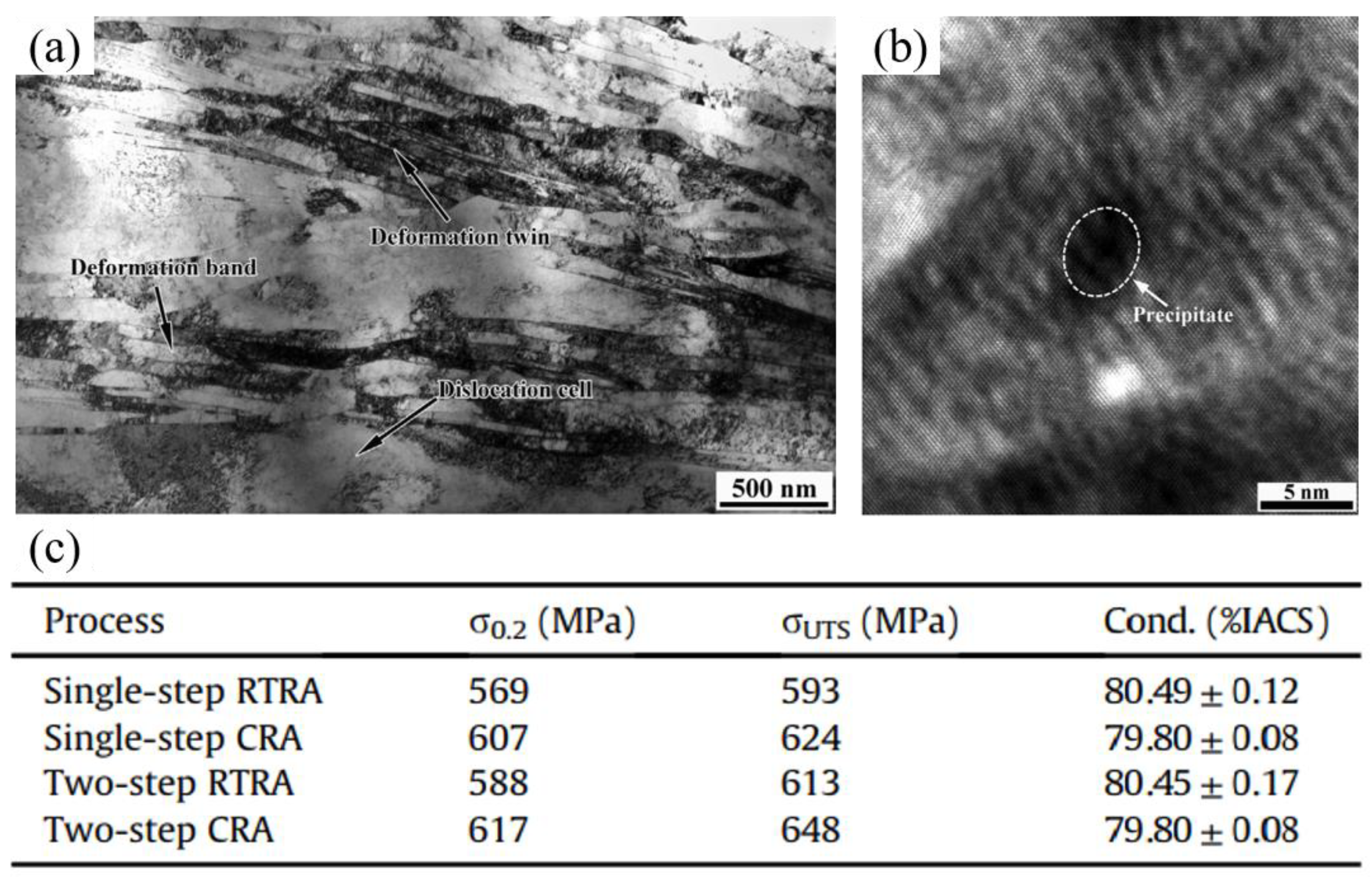
| Two-step cryorolling + aging | 648 | 79.8 | [76] |
| Annealing + LNT-DPD a | 700 | 98.5 | [77] |
| ST b + ECAP c × 2 + HE d + aging | 625 | 78.0 | [78] |
| ST b + HE d + aging | 630 | 79.0 | [78] |
| ST + CEF e + drawing + aging | 590 | 77.6 | [79] |
| ST + cold drawing + aging | 550 | 78.7 | [79] |
| ST + ECAP × 4 + aging | 577 | 78.5 | [80] |
Disclaimer/Publisher’s Note: The statements, opinions and data contained in all publications are solely those of the individual author(s) and contributor(s) and not of MDPI and/or the editor(s). MDPI and/or the editor(s) disclaim responsibility for any injury to people or property resulting from any ideas, methods, instructions or products referred to in the content. |
© 2024 by the authors. Licensee MDPI, Basel, Switzerland. This article is an open access article distributed under the terms and conditions of the Creative Commons Attribution (CC BY) license (https://creativecommons.org/licenses/by/4.0/).
Share and Cite
Wang, X.; Yao, P.; Zhou, H.; Fan, K.; Deng, M.; Kang, L.; Yuan, Z.; Lin, Y. Research Progress on Surface Damage and Protection Strategies of Armature–Rail Friction Pair Materials for Electromagnetic Rail Launch. Materials 2024, 17, 277. https://doi.org/10.3390/ma17020277
Wang X, Yao P, Zhou H, Fan K, Deng M, Kang L, Yuan Z, Lin Y. Research Progress on Surface Damage and Protection Strategies of Armature–Rail Friction Pair Materials for Electromagnetic Rail Launch. Materials. 2024; 17(2):277. https://doi.org/10.3390/ma17020277
Chicago/Turabian StyleWang, Xing, Pingping Yao, Haibin Zhou, Kunyang Fan, Minwen Deng, Li Kang, Zihao Yuan, and Yongqiang Lin. 2024. "Research Progress on Surface Damage and Protection Strategies of Armature–Rail Friction Pair Materials for Electromagnetic Rail Launch" Materials 17, no. 2: 277. https://doi.org/10.3390/ma17020277
APA StyleWang, X., Yao, P., Zhou, H., Fan, K., Deng, M., Kang, L., Yuan, Z., & Lin, Y. (2024). Research Progress on Surface Damage and Protection Strategies of Armature–Rail Friction Pair Materials for Electromagnetic Rail Launch. Materials, 17(2), 277. https://doi.org/10.3390/ma17020277