Communication

Numerical Study on a Ductile Fracture Model in Pre-Cracked Tension Tests of SUS304L

1
Department of Marine Mobility, Tongmyong University, Busan 48520, Republic of Korea
2
Open Grid Laboratory, Busan 48520, Republic of Korea
3
Korea Research Institute of Ships and Ocean Engineering, Daejeon 34103, Republic of Korea
4
LS Cable & System, Gunpo 15845, Republic of Korea
*
Authors to whom correspondence should be addressed.
Materials 2024, 17(2), 276; https://doi.org/10.3390/ma17020276
Submission received: 5 December 2023 / Revised: 29 December 2023 / Accepted: 3 January 2024 / Published: 5 January 2024

Abstract

:
The effectiveness of a ductile fracture model in accurately predicting fracture initiation has been demonstrated. In this study, we concentrate on applying the ductile fracture model to pre-cracked structures constructed from SUS304L stainless steel with experimental and numerical analyses. The Swift hardening law was employed to extend the plastic behavior beyond the onset of necking. Additionally, the Hosford–Coulomb model, integrated with a damaged framework, was utilized to predict ductile fracture behavior, particularly under non-proportional loading conditions. Tension tests were conducted on various specimens designed to illustrate various fracture modes resulting from geometric effects. Numerical analyses were conducted to explore the loading histories, utilizing an optimization process to calibrate fracture model parameters. The proposed fracture model is validated against pre-cracked structures detailed in a reference paper. The results convincingly demonstrate that the fracture model effectively predicts both fracture initiation and propagation in pre-cracked structures.

1. Introduction

The prediction of ductile fracture initiation holds a central position in the domains of structural engineering and materials science, exerting profound influence over the safety, dependability, and functionality of engineering components and structures. In the shipbuilding industry, fracture analysis is crucial for assessing the behavior of structures under large deformations caused by extreme loads, such as ship collisions, grounding, and explosions. Ductile fracture, characterized by its gradual deformation and energy-absorbing properties, stands in stark contrast to brittle fracture, which has the potential to culminate in abrupt and catastrophic failures. In numerous engineering applications, the ramifications of structural failure can be extraordinarily severe, encompassing not only substantial economic repercussions but, of even greater consequence, threats to human safety. The ability to predict ductile fracture empowers engineers with the means to evaluate precisely when and under what circumstances a material or component might approach its deformation limits. This, in turn, furnishes invaluable insights for averting catastrophic failures and underpins the foundations of safety within the realm of engineering.
Researchers have dedicated considerable effort over the past few decades to explore and develop various fracture models to elucidate the behavior of ductile fractures. These models can be broadly categorized as either uncoupled or coupled fracture models [1]. Uncoupled models are expressed by the function of critical value in terms of the stress and strain fields. For instance, Rice and Tracey presented a damage model with a hydrostatic stress term grounded in the theory of void development [2]. It posits that, under tensile loading, macroscopic fracture initiation occurs when voids expand and contract until they reach critical void volume friction. The model employs a critical stress triaxiality value to estimate the point at which void coalescence occurs. The modified Mohr–Coulomb (MMC) model was expressed by the stress-based Mohr–Coulomb criterion into stress and strain fields [3,4]. The Hosford–Coulomb (HC) model, developed based on the Hosford yield criteria, was expressed as mixed stress–strain fields [5]. These models find frequent use in addressing ductile fracture-related challenges, owing to their simplicity in parameter calibration [6,7,8,9,10,11,12,13,14]. The Bressan–Williams-Hill (BWH) criterion was developed based on Hill’s localized necking criterion to introduce a stress-based Forming Limit Curve (FLC) that could be used to predict fracture initiation with shell elements [15]. Subsequently, an extended strain-based version of the BWH model was derived [16,17]. Cerick et al. Lou and Huh [18,19,20] introduced a Lou-Huh ductile fracture model for predicting sheet metals, a model subsequently validated by numerous researchers [21,22,23,24]. Park et al. [25] conducted a comparative study to assess the accuracy of different fracture models (Maximum shear stress, Johnson–Cook [26], Lou–Huh [18], modified Mohr–Coulomb [4], Hosford–Coulomb [5]) in predicting fractures in DH36-grade steel. The findings of this paper indicate that recent fracture models (Lou–Huh, modified Mohr–Coulomb, Hosford–Coulomb), which explicitly incorporate stress triaxiality and lode angle parameters, exhibit superior performance.
Pre-existing cracks within a structure can arise due to various factors, including fatigue, manufacturing imperfections, corrosion, and impacts. These pre-cracks pose significant concerns, particularly in critical applications, as they can compromise structural integrity and safety. Understanding the origin and behavior of these pre-cracks is of the utmost importance for structural assessment and risk mitigation. This study explored the utilization of ductile fracture locus models for predicting complex failure modes in pre-cracked structures, utilizing an engineering aluminum alloy specimen with a side notch and pre-crack [27]. Their study demonstrates the effectiveness of the numerical approach, which combines the fracture locus theory and local damage modeling in accurately predicting failure processes using the ductile fracture model. A computational approach was employed, incorporating a unified elastoviscoplastic-damage model, and the presented model was validated through pre-crack tests [28]. A numerical approach was conducted to simulate a ductile fracture in cracked pipes, employing small punch test data and a multi-axial fracture strain energy density model [29].
Park et al. [25] conducted fracture tests and simulations on EH36-grade steel, and the loading history effect was taken into account by assessing the average values of stress triaxiality and the lode angle parameter. Cerik et al. [30] explored ductile crack formation in DH36-grade steel. While there has been substantial research on the fracture behavior of marine steel, there is a noticeable lack of research on materials relevant to shipbuilding and marine equipment, such as hydrogen tanks. This paper focuses on examining the plastic and ductile fracture characteristics of stainless steel SUS304L used for the hydrogen storage tank. In this pursuit, we employed the Swift hardening law to characterize plasticity behavior, which was complemented by adopting the Hosford–Coulomb model augmented with a damaged framework for simulating ductile fracture. To fine-tune and identify the model parameters, we subjected the specimens to quasi-static tests and conducted finite element analysis under various failure modes. Furthermore, we rigorously validated the presented fracture model, particularly in pre-cracked structure scenarios, by undertaking fracture simulations for the double-edge cracked tension test. The validation process involved meticulously comparing the model predictions with the results obtained from numerical simulations.

2. Experiment and Plasticity Model

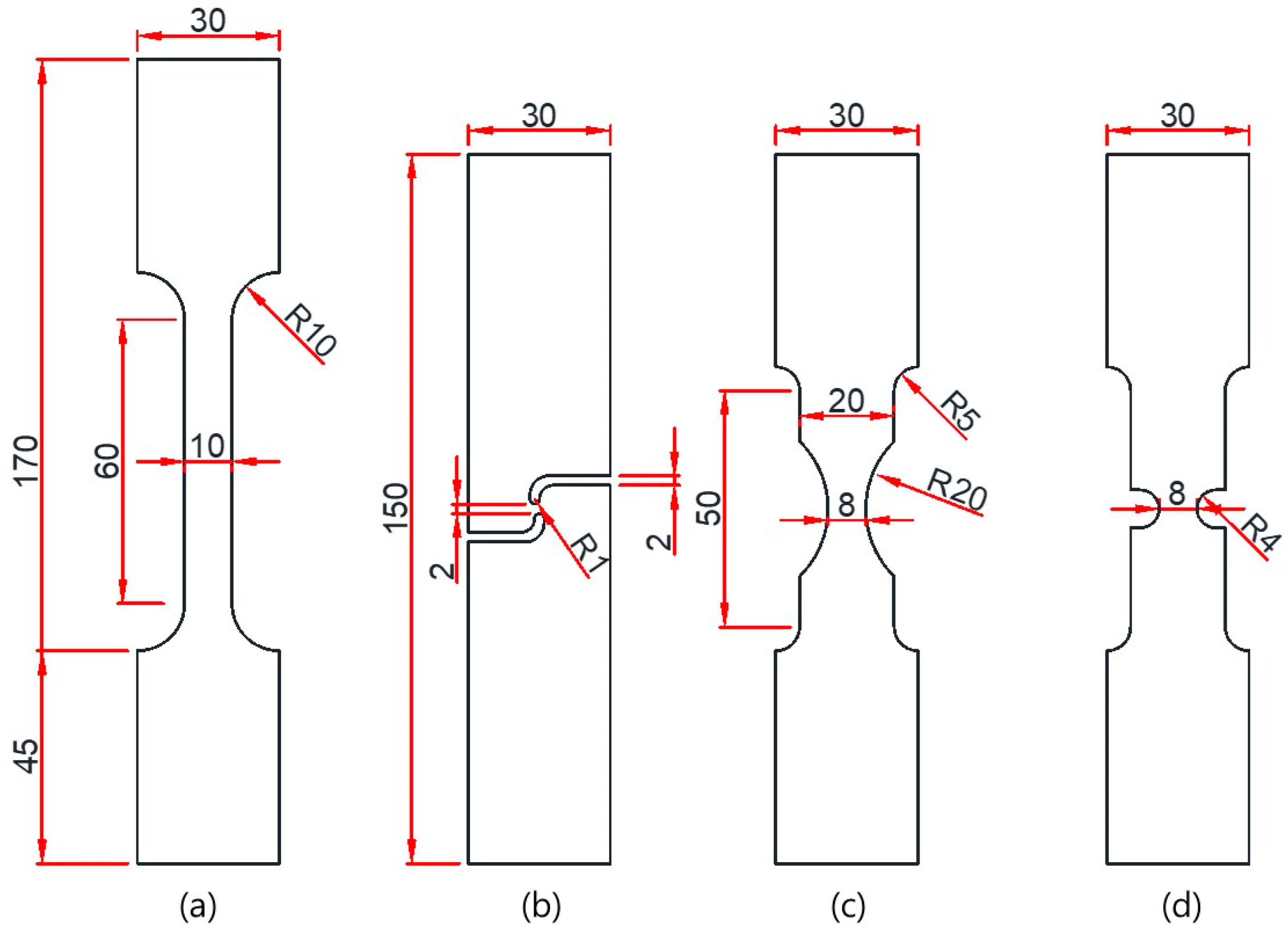
2.1. Fracture Experiment

Quasi-static tests were performed to investigate the plasticity characteristics and fracture model parameters of SUS304L. The chemical composition of this material is provided in Table 1. Figure 1 illustrates the dimensions and labels of the uniaxial tension specimens specifically designed to induce different fracture modes. All specimens had a thickness of 2.0 mm. The standard flat bar type specimen (FB) with a 60.0 mm gauge length and 10.0 mm gauge section was specifically designed to obtain mechanical properties in compliance with ASTM E08 standards [31]. The notch tension specimen (NT) featured a circular cut-out with a 20.0 mm radius for the notch. The plane strain tension specimen (PST) had a 4.0 mm radius for the notch. The shear specimen (SH) was specially designed to occur pure shear in the uniaxial tension test. Uniaxial tension tests were conducted using a servo-mechanical loading frame (Samyeon Tech, Daegu, Republic of Korea) with a 50 mm extensometer (Epsilon Tech, Jackson, WY, USA). The testing speed was set at 2.0 mm/min, and all tests were performed at room temperature.

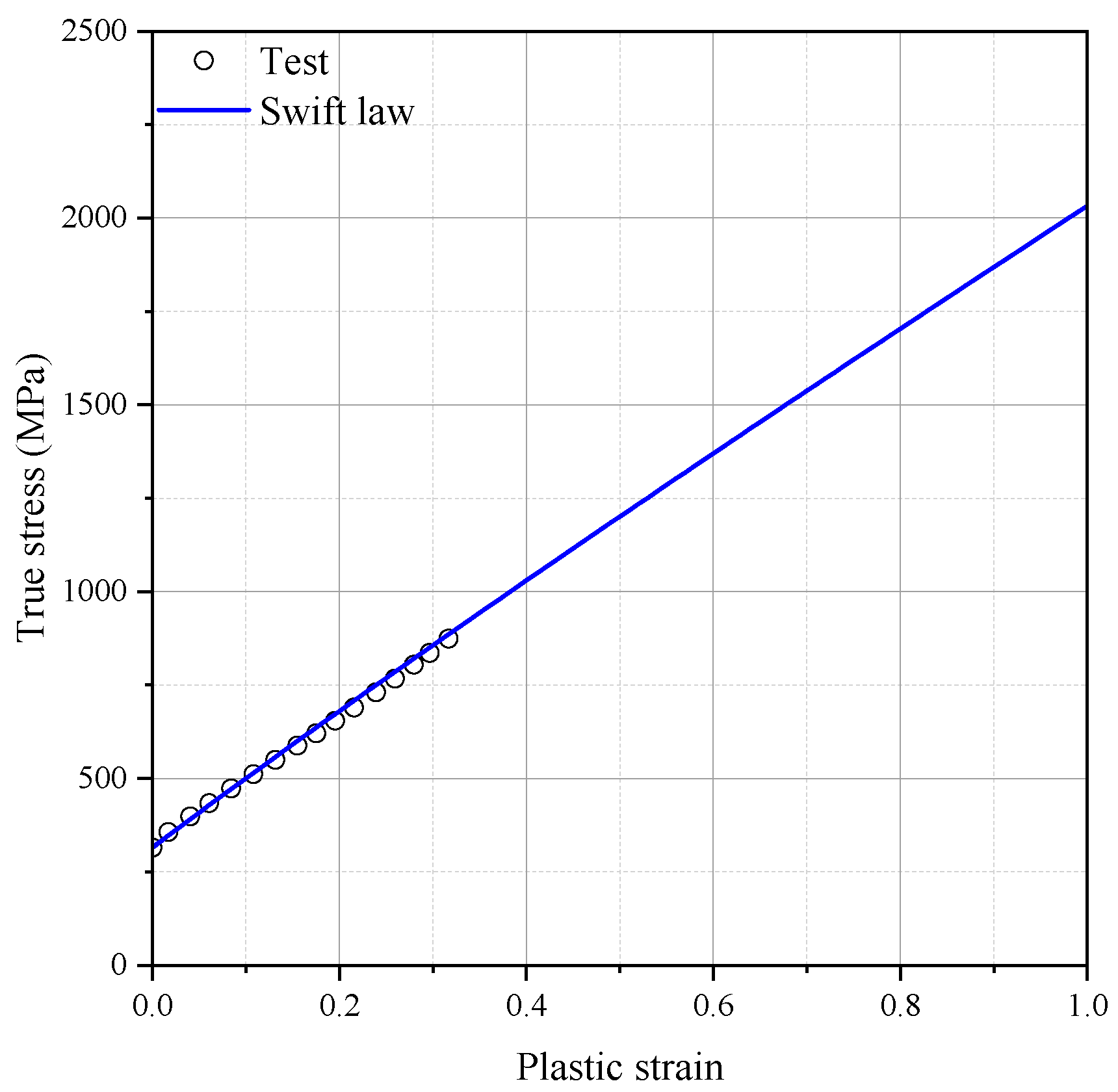
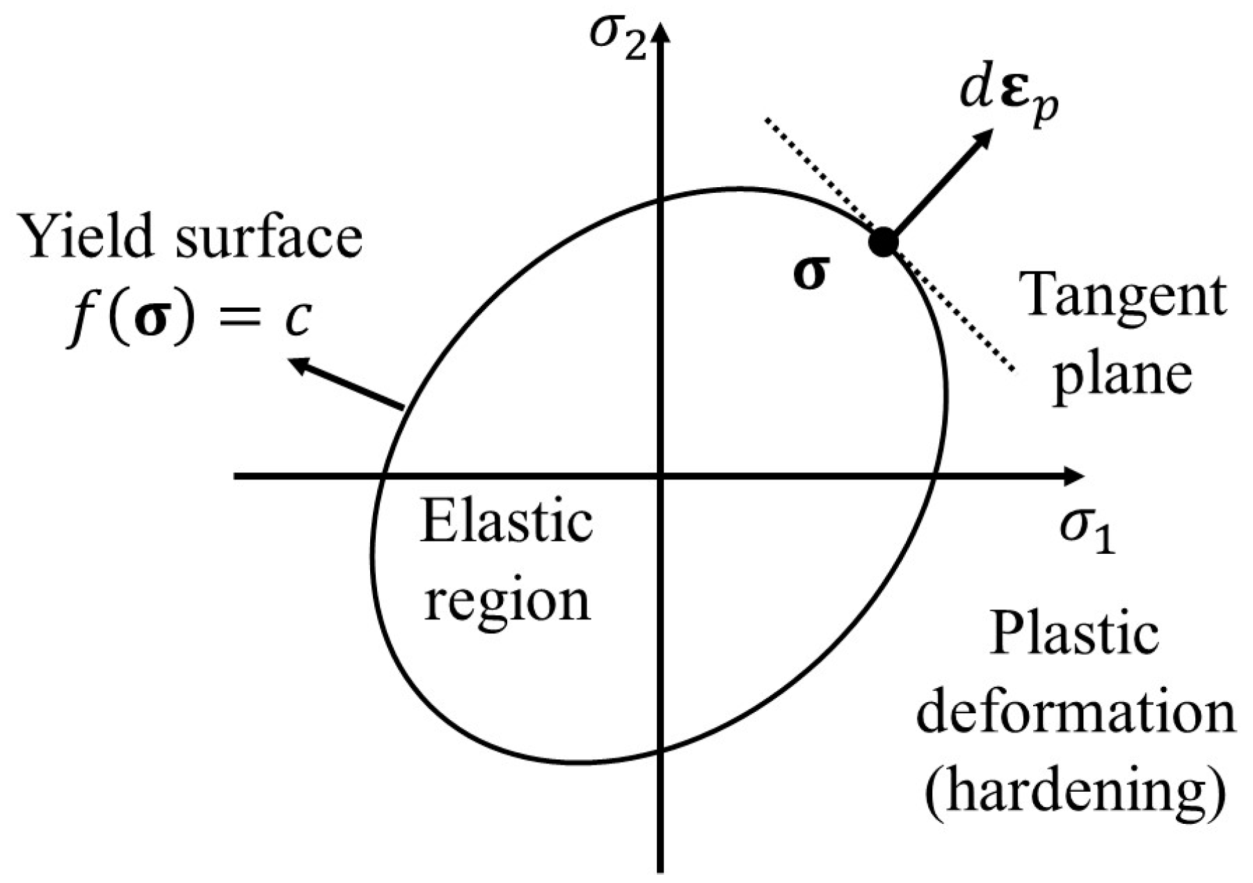
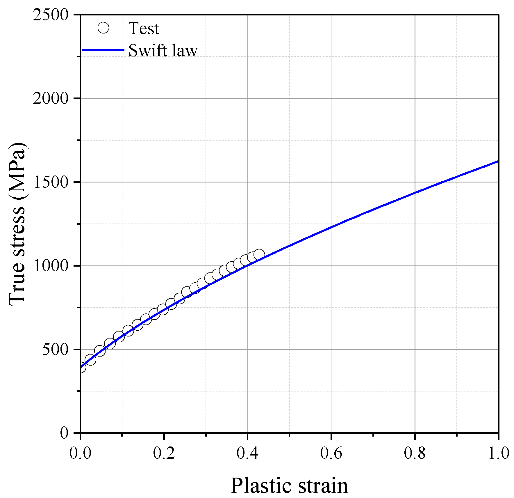
2.2. Plasticity Model

The exact flow stress information during plastic deformation is essential to improve the accuracy of fracture simulation. The yield stress criterion f of isotropic material is expressed by the von Mises equivalent stress σ ¯ and deformation resistance k :
f σ , k = σ ¯ k ε ¯ p = 0
The σ ¯ is a scalar value computed from the Cauchy stress tensor, σ . ε ¯ p is the equivalent plastic strain. An associated flow rule follows the plastic potential theory as shown below:
d ε p = d λ f σ
As shown in Figure 2, plastic deformation occurs when σ exceeds the surface yield. The plastic multiplier d λ > 0 is described using the hardening parameter. In this study, the Swift isotropic hardening law was adopted to describe the stress–strain relationship over the onset of necking:
k ε ¯ p = A ε 0 + ε ¯ p n
The Swift isotropic hardening law is defined by three parameters ε 0 ,   A ,   n .

2.3. Plasticity Model Calibration

Before the onset of necking, the flow stress was obtained from the tensile test for the FB specimen. The hardening model parameters are determined by an iterative approach based on experimental and numerical results for the FB and NT specimens. The stress–strain curves before the onset of necking were obtained using standard tension tests on flat bar specimens, and the flow stress beyond the large plastic strain region was extrapolated using the hardening law. The presented hardening model parameters were verified through numerical analysis for the cases of NT, PST, and SH. The detailed calibration procedure was introduced in a previous study [6]. Figure 3 illustrates the finite element (FE) model, which includes one-eighth of the gauge section and was created using eight-node solid elements (C3D8R). The element size of 0.1 mm was determined through a convergence test, i.e., ten elements were meshed at half thickness. Figure 4 shows the hardening curves of the tension test for FB and extrapolated flow stress using the MATLAB curve fitting tool (Natick, MA, USA) with the Swift hardening equation and the test result. The identified Swift hardening model parameters were A = 1778.0 , ε 0 = 0.1514 , n = 0.928 , respectively.

3. Fracture Model Calibration

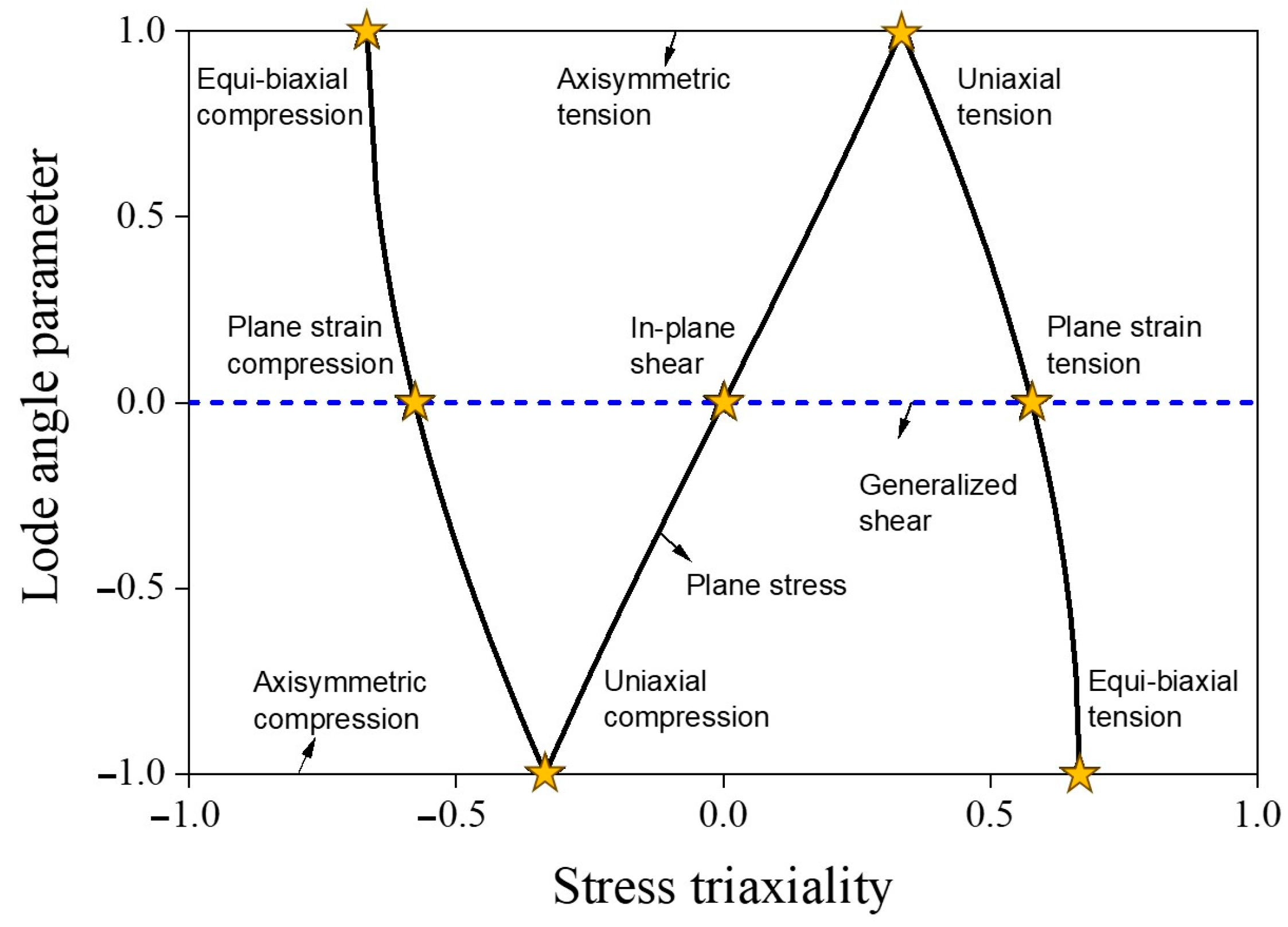
3.1. Characterization of Stress State

The stress state of an isotropic ductile material can be elucidated through dimensionless parameters as follows: stress triaxiality denoted as η and the lode angle parameter represented as θ ¯ . These two stress state parameters can be represented in the plane stress state, as shown in Figure 5. These parameters are formulated based on the invariants of the Cauchy stress tensor and can be articulated as follows:
I 1 = t r σ
J 2 = 1 2 s : s
J 3 = d e t [ s ]
I 1 represents the first invariant of the Cauchy stress tensor, denoted as σ . J 2 and J 3 are the second and third invariants of the deviatoric stress tensor, referred to as s . They represent the combined influence of the magnitude and direction of shear stress. η and θ ¯ are expressed as follows:
η = I 1 3 3 J 2
θ ¯ = 1 2 π cos 1 3 3 2 J 3 J 2 3 2   = 1 2 π cos 1 27 2 J 3 σ ¯ 3  
σ ¯ means the equivalent von Mises stress:
σ ¯ = 3 J 3 = 1 2 σ 1 σ 2 2 + σ 2 σ 3 2 + σ 3 σ 1 2  
The principal stresses σ 1 , σ 2 , σ 3 can be written as η and θ ¯ :
σ 1 = σ ¯ η + 2 3 cos π 6 1 θ ¯
σ 2 = σ ¯ η + 2 3 cos π 6 3 + θ ¯
σ 3 = σ ¯ η 2 3 cos π 6 1 + θ ¯

3.2. Hosford–Coulomb Fracture Model

The Hosford–Coulomb (HC) model with the damaged framework is widely used to predict the onset of the fracture initiation of ductile material under non-proportional loading. The Hosford–Coulomb model was represented by the Tresca equivalent stress with the Hosford equivalent stress, σ H C :
σ H C + c σ 1 + σ 3 = b
σ H C = 1 2 σ 1 σ 2 a + σ 2 σ 3 a + σ 1 σ 3 a 1 a
where b is the material-dependent constant and c is the friction coefficient. σ H C is expressed in terms of the modified Haigh–Westergaard coordinates σ ¯ , η , θ ¯ using Equations (10)–(12):
σ ¯ = σ f η , θ ¯ = b 1 2 f 1 f 2 a + f 2 f 3 a + f 1 f 3 a 1 a + c 2 η + f 1 + f 3
where σ ¯ f is the von Mises equivalent stress at fracture under proportional loading. The lode angle parameter function f 1 , f 2 , f 3 is expressed as follows:
f 1 θ ¯ = 2 3 cos π 6 1 θ ¯
f 2 θ ¯ = 2 3 cos π 6 3 + θ ¯
f 3 θ ¯ = 2 3 cos π 6 1 + θ ¯
Derived from the isotropic power law, ε ¯ p = k 1 σ ¯ , the fracture strain of the Hosford–Coulomb model for a proportional loading path, ε ¯ H C p r can be reformulated in a mixed stress/strain space η , θ ¯ , ε ¯ H C p r as follows:
ε ¯ H C p r η ,   θ ¯ = b 1 + c 1 / n H C     g η ,   θ ¯
g η ,   θ ¯ = 1 2 f 1 f 2 a + f 2 f 3 a + f 1 f 3 a 1 a + c 2 η + f 1 + f 3 1 n H C
The coefficient, n H C , is generally set to 0.1 for general ductile steel [18,19]. Finally, the Hosford–Coulomb model consists of three parameters a , b , c . The damage framework is used to consider the non-proportional loading effect. In this study, the linear damage accumulation law is adopted with the HC model [20]. The damage indicator, D 0 , 1 , is expressed by the equivalent plastic strain, ε ¯ p , f , and the integration of the weighting function, ε ¯ H C p r η , θ ¯ along the loading history, as follows:
D = 0 ε ¯ p , f d ε ¯ p ε ¯ H C p r η ,   θ ¯

3.3. Fracture Model Parameter Identification

The commercial finite element analysis software Abaqus 2023 was used to investigate the history of the stress state to fracture initiation. The accuracy of the numerical simulation was verified by comparing it to the test results, as illustrated in Figure 6. Determining the fracture initiation displacement is challenging, especially if it occurs inside the specimen, even when measured using a monitoring device. Fracture initiation was assumed to take place at the element where the maximum equivalent plastic strain was observed during fracture displacement. Figure 7 displays the contour plots obtained from finite element analysis with equivalent plastic strain. In the notch tension specimen, fracture initiation occurred at the center of the notch, while in the plain strain tension specimen, it was observed at the side of the notch. For the shear specimen, a fracture occurred at the center of the notch. Figure 8 displays the loading history leading to fracture, with the lowest ductility observed in the shear fracture mode.
Optimization was carried out to calibrate the HC model parameters a , b , c using the objective function f χ . The linear damage model was used for the optimization procedure described as follows:
f χ = i = 1 3 0 ε ¯ f d ε ¯ p ε ¯ f p r η , θ 1 2
Therefore, the optimization problem is expressed as
χ = a r g m i n χ f χ
The index i indicates the number of experiments for calibration. In this study, three tests, NT, PST, and SH were used for calibration. The optimization procedure was conducted using MATLAB, and the calibrated HC model parameters were a = 1.3358 , b = 0.8047 , c = 0.0002 . Figure 9a illustrates 3D fracture loci with a red line representing the plane stress condition, while Figure 9b shows the fracture loci under the plane stress condition. The ductility limit of SUS304L was dependent on the lode angle parameter. A change in stress triaxiality did not significantly affect the variation in fracture strain. It is worth noting that the fracture locus exhibited the lowest ductility in the plane strain tension state.

4. Application to Pre-Cracked Tension Test

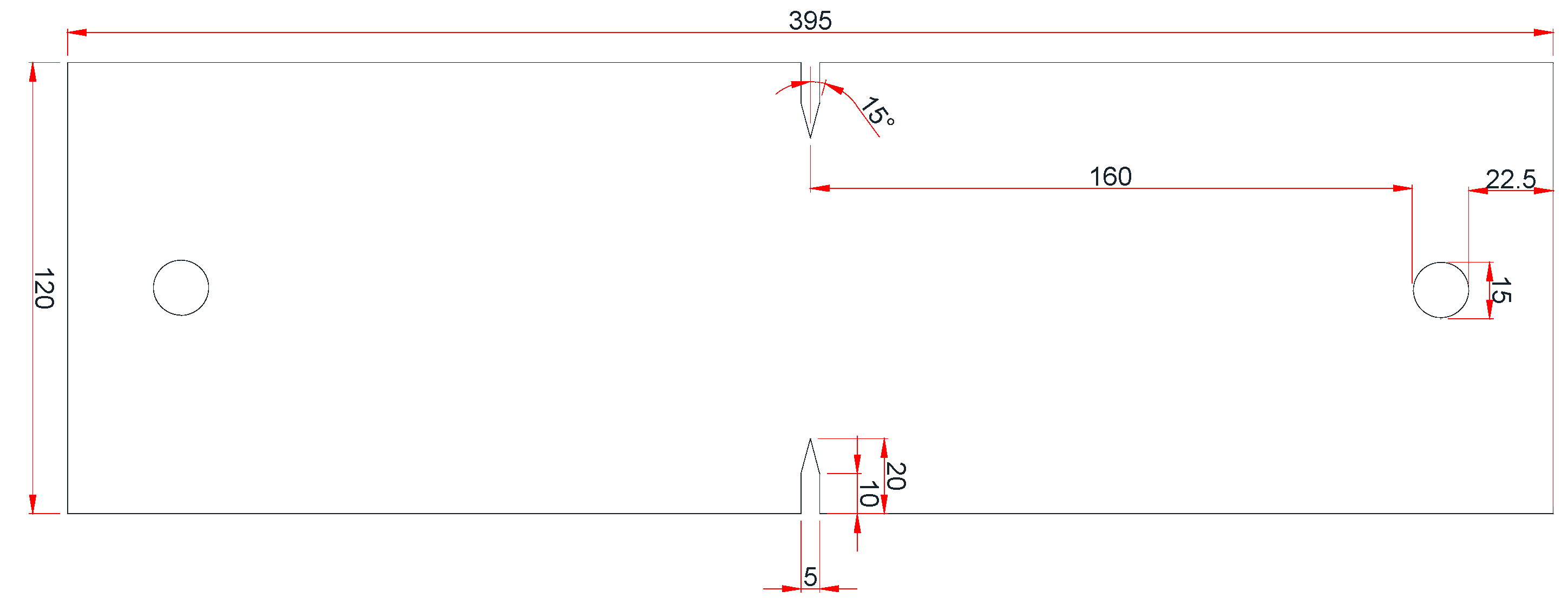
4.1. Description of Reference Test

Tension tests were conducted on SUS304L specimens with an initial crack, named the double-edge cracked tension test (DECT) [28]. These experiments were specifically designed to resemble structures with an initial crack. Figure 10 illustrates the specimen’s geometry, with a thickness of 1.2 mm. Furthermore, standard dog bone-type specimens were subjected to tensile tests to acquire the mechanical properties of SUS304L. In all cases, the tests continued until fracture took place at a consistent loading rate of 1 mm/min.

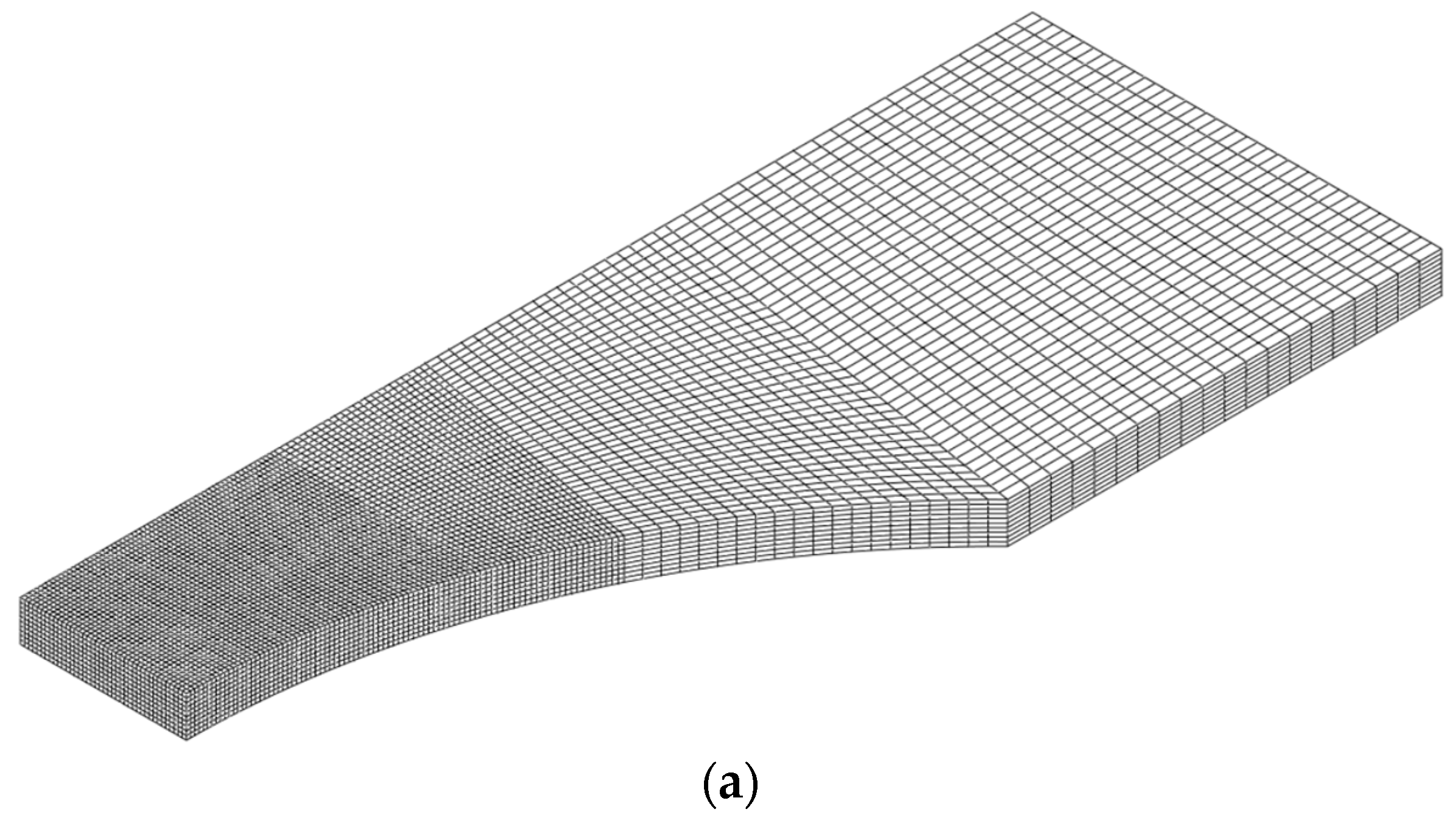
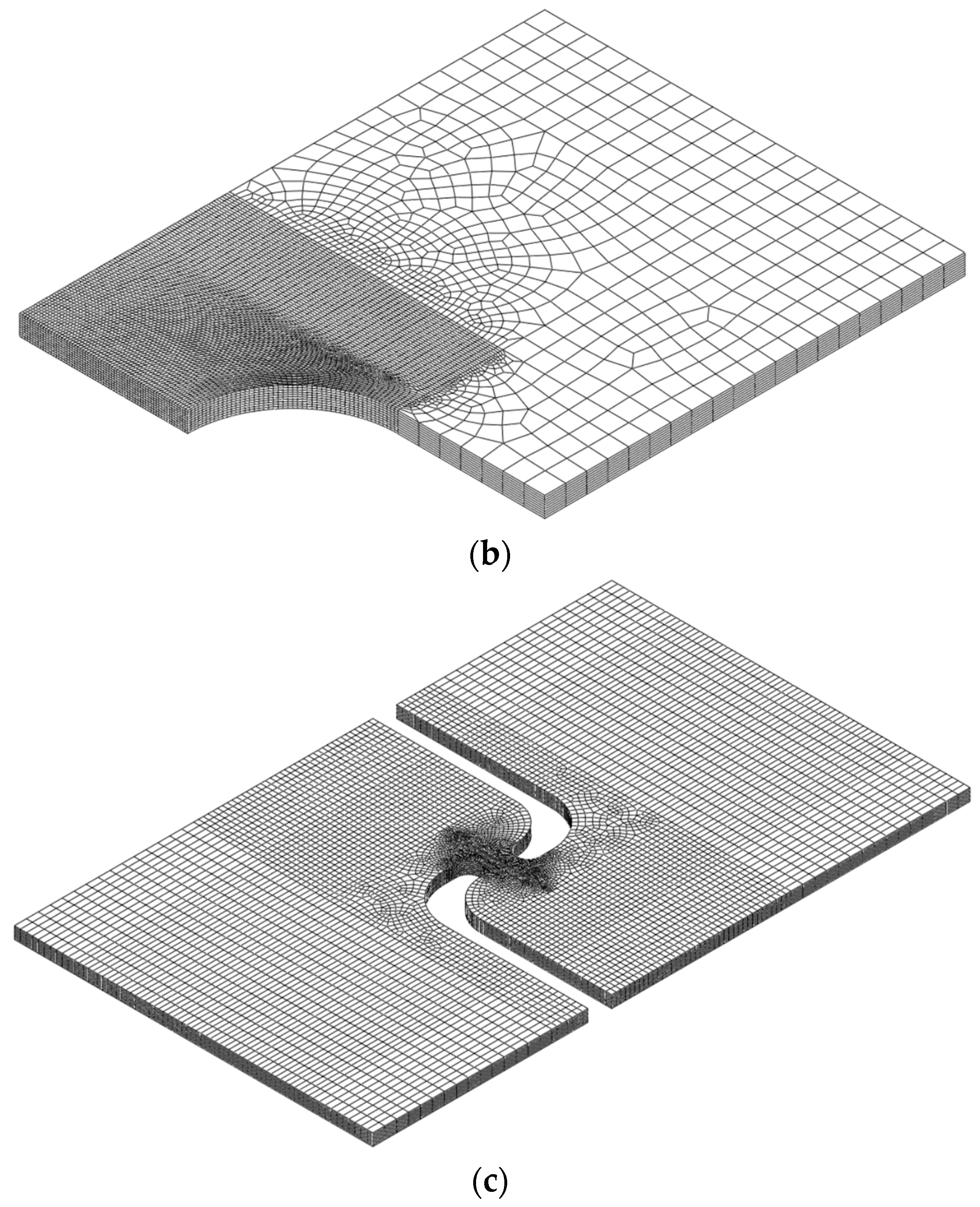
4.2. FE Model and Fracture Simulation

To perform fracture simulation using the proposed HC model for SUS304L, a quarter finite element (FE) model of DECT was created. The model used a reduced integration-type solid element (C3D8R in Abaqus). as illustrated in Figure 11. The finite element model was created under 1/8 of the symmetric conditions for length, width, and thickness. The model was meshed with six elements in half of its thickness. The enforced displacement was applied at the top node. Mesh sensitivity issues near the crack tip line were addressed in a previous study, and the element length around the crack tip was determined to be 0.1 mm [22]. The ABAQUS/explicit user-defined subroutine VUMAT was developed to define the damage indicator at every Gauss point in finite element analysis [6]. This element experienced a loss of stiffness when the damage indicator reached a value of one.
Swift model parameters were re-modeled to improve the accuracy of numerical prediction and also address the effect of uncertainty in the material property ranges. As shown in Figure 12, the fracture simulation for DECT was performed with the newly identified Swift model parameters of A = 1517.0 , ε 0 = 0.1156 , n = 0.6265 . The accuracy of the fracture model was validated by comparing the force and displacement curves between the experiment and fracture simulation.
Figure 13 presents the test results and numerical results from the reference paper [28] alongside the fracture simulation results using the HC model. It is demonstrated that the error in terms of fracture displacement was reduced when utilizing the HC model compared to the viscoplastic-damage model presented in the previous study.

5. Conclusions

The research presented here focuses on the plasticity and ductile fracture models applicable to SUS304L steel, employing the Swift isotropic hardening law for plasticity and the Hosford–Coulomb model with a damaged framework for simulating ductile fracture. The results provide the below conclusions:
  • Quasi-static tensile tests were conducted on SUS304L, a material commonly used for structural steel and, more recently, in hydrogen tanks. The flow stress beyond the onset of necking was obtained for numerical analysis involving large deformation and fracture.
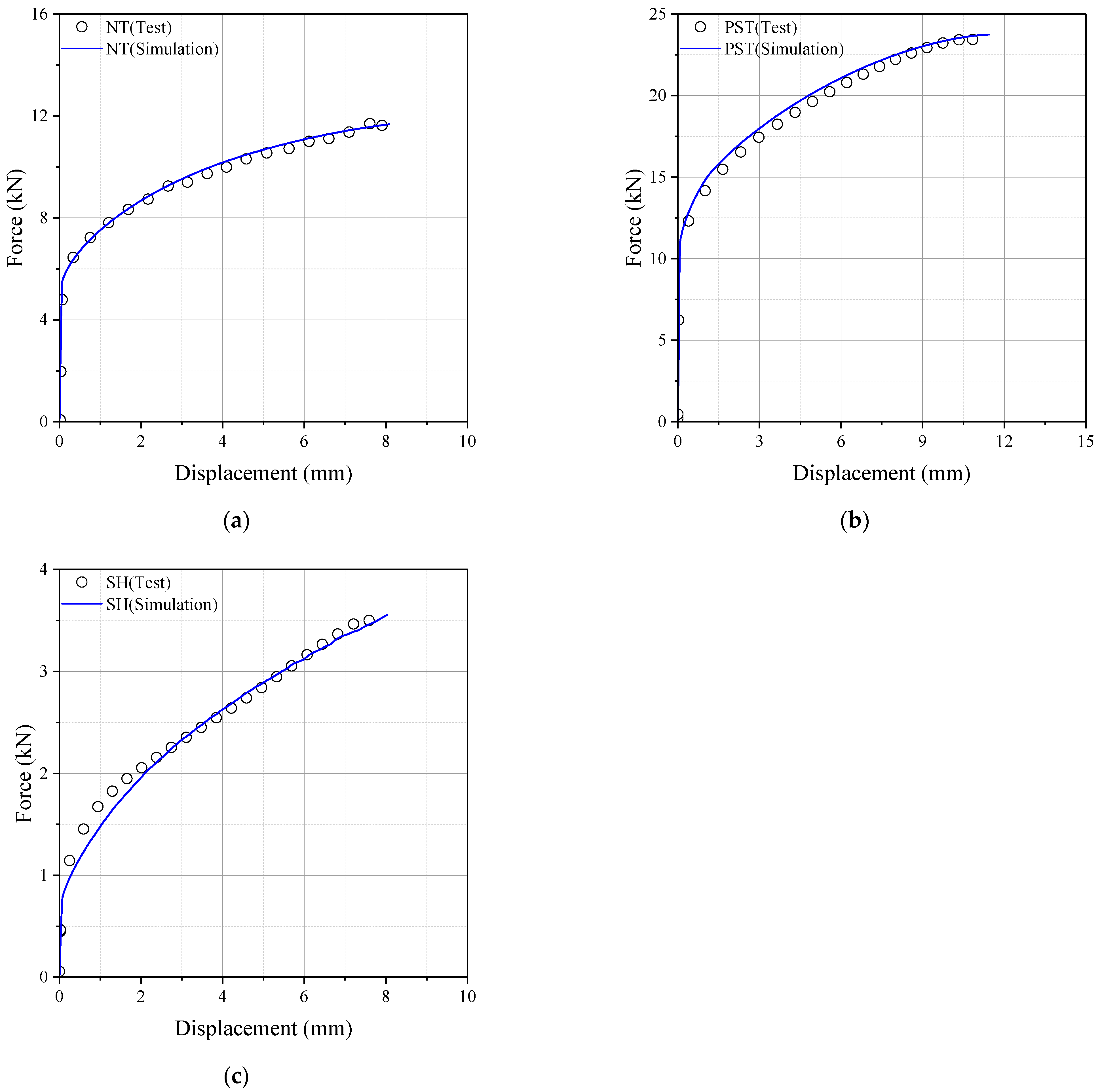
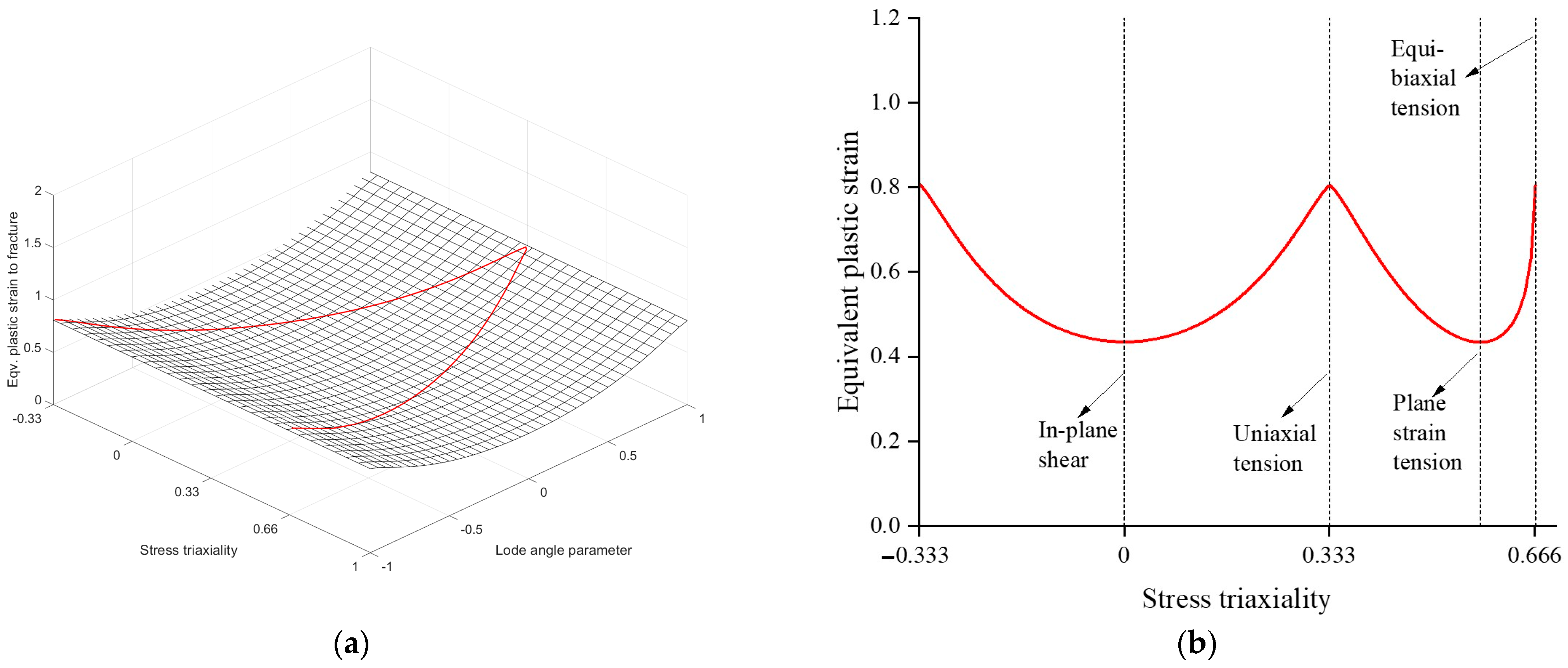
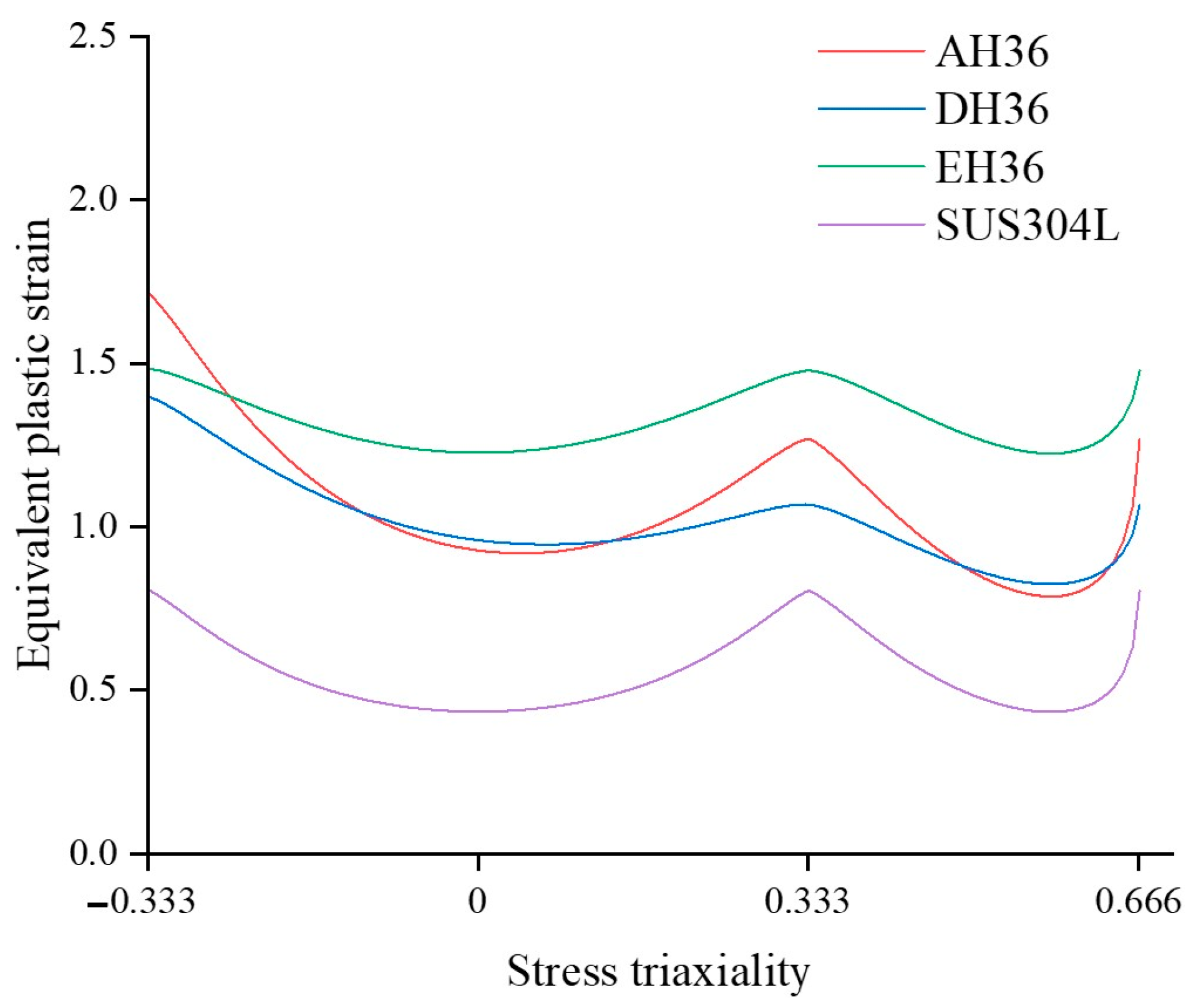
  • Numerical simulations were employed to obtain the loading history until the initiation of fracture, and the Hosford–Coulomb model parameters were determined using an optimization process within a damaged framework. Figure 14 illustrates the 2D ductile fracture loci of AH36, DH36, EH36, and SUS304L steel under plane stress conditions. In all fracture models, the lowest ductility was observed in the plane strain tension state. Notably, SUS304L steel exhibited lower ductility compared to other general shipbuilding steels.
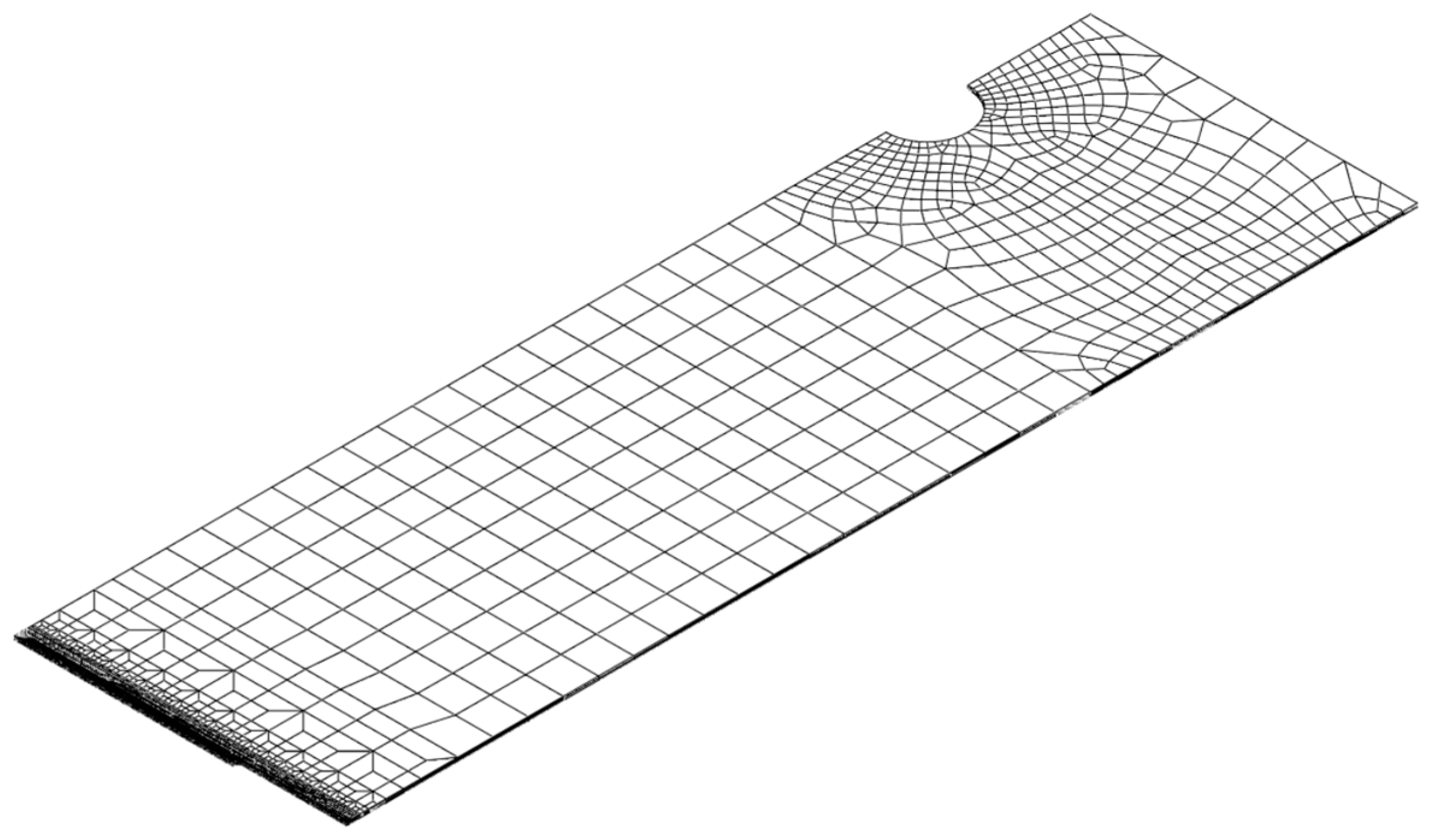
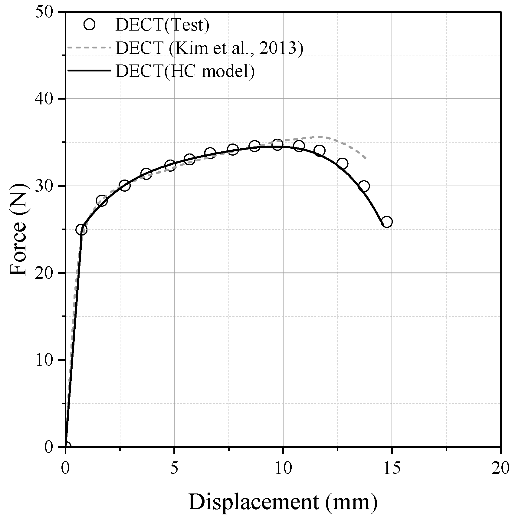
  • The proposed Hosford–Coulomb (HC) model underwent validation through numerical simulations of double-edge cracked tension tests. These results underscore the effectiveness of the HC model in reducing errors in fracture displacement predictions when compared to previous methods, thereby enhancing the accuracy of fracture simulations.
This work contributes to the understanding and prediction of ductile fracture behavior in pre-cracked structures, providing valuable insights for structural assessment, risk mitigation, and the development of safer engineering components and structures.

Author Contributions

Conceptualization, S.-J.P.; formal analysis, S.-J.P. and W.N.; investigation, B.P. and K.L.; methodology, S.-J.P. and B.P.; software, S.-J.P. and W.N.; validation, S.-J.P. and W.N.; visualization, S.-J.P. and K.K.; writing—original draft, S.-J.P.; writing—review and editing, W.N. All authors have read and agreed to the published version of the manuscript.

Funding

This research was supported by a grant from the Endowment Project of “Core Technology Development of Hydro-elasticity based Structural Damage Assessment for Offshore Structures considering Uncertainty (4/5)”, funded by the Korea Research Institute of Ships and Ocean Engineering (PES4770).

Institutional Review Board Statement

Not applicable.

Informed Consent Statement

Not applicable.

Data Availability Statement

Data are contained within the article.

Conflicts of Interest

Author Woongshik Nam was employed by the company LS Cable & System. The remaining authors declare that the research was conducted in the absence of any commercial or financial relationships that could be construed as a potential conflict of interest.

References

  1. Lee, S.Y.; Kim, J.H.; Barlat, F.; Kim, H.S. Numerical Fracture Prediction of Martensitic Steel by Uncoupled and Coupled Type Fracture Models. Eng. Fract. Mech. 2023, 289, 109396. [Google Scholar] [CrossRef]
  2. Rice, J.R.; Tracey, D.M. On the Ductile Enlargement of Voids in Triaxial Stress Fields*. J. Mech. Phys. Solids 1969, 17, 201–217. [Google Scholar] [CrossRef]
  3. Bai, Y.; Wierzbicki, T. A New Model of Metal Plasticity and Fracture with Pressure and Lode Dependence. Int. J. Plast. 2008, 24, 1071–1096. [Google Scholar] [CrossRef]
  4. Bai, Y.; Wierzbicki, T. Application of Extended Mohr-Coulomb Criterion to Ductile Fracture. Int. J. Fract. 2010, 161, 1–20. [Google Scholar] [CrossRef]
  5. Mohr, D.; Marcadet, S.J. Micromechanically-Motivated Phenomenological Hosford–Coulomb Model for Predicting Ductile Fracture Initiation at Low Stress Triaxialities. Int. J. Solids Struct. 2015, 67–68, 40–55. [Google Scholar] [CrossRef]
  6. Park, S.-J. Application of Ductile Fracture Model for the Prediction of Low Cycle Fatigue in Structural Steel. Eng. Fract. Mech. 2023, 289, 109469. [Google Scholar] [CrossRef]
  7. Boyce, B.L.; Kramer, S.L.B.; Fang, H.E.; Cordova, T.E.; Neilsen, M.K.; Dion, K.; Kaczmarowski, A.K.; Karasz, E.; Xue, L.; Gross, A.J.; et al. The Sandia Fracture Challenge: Blind Round Robin Predictions of Ductile Tearing. Int. J. Fract. 2014, 186, 5–68. [Google Scholar] [CrossRef]
  8. Kramer, S.L.B.; Jones, A.; Mostafa, A.; Ravaji, B.; Tancogne-Dejean, T.; Roth, C.C.; Bandpay, M.G.; Pack, K.; Foster, J.T.; Behzadinasab, M.; et al. The Third Sandia Fracture Challenge: Predictions of Ductile Fracture in Additively Manufactured Metal. Int. J. Fract. 2019, 218, 5–61. [Google Scholar] [CrossRef]
  9. Boyce, B.L.; Kramer, S.L.B.; Bosiljevac, T.R.; Corona, E.; Moore, J.A.; Elkhodary, K.; Simha, C.H.M.; Williams, B.W.; Cerrone, A.R.; Nonn, A.; et al. The Second Sandia Fracture Challenge: Predictions of Ductile Failure under Quasi-Static and Moderate-Rate Dynamic Loading. Int. J. Fract. 2016, 198, 5–100. [Google Scholar] [CrossRef]
  10. Roth, C.C.; Mohr, D. Determining the Strain to Fracture for Simple Shear for a Wide Range of Sheet Metals. Int. J. Mech. Sci. 2018, 149, 224–240. [Google Scholar] [CrossRef]
  11. Shang, M.; Yang, H.; Su, A.; Wang, Y. Strain-Rate and Stress-State Dependent Ductile Fracture Model of S690 High-Strength Steel. J. Constr. Steel Res. 2023, 204, 107852. [Google Scholar] [CrossRef]
  12. Li, X.; Yu, R.; Wang, P.; Kang, R.; Shu, Z.; Yue, Z.; Zhao, Z.; Wang, X.; Lu, T.J. Plastic Deformation and Ductile Fracture of L907A Ship Steel at Increasing Strain Rate and Temperature. Int. J. Impact Eng. 2023, 174, 104515. [Google Scholar] [CrossRef]
  13. Wilson-Heid, A.E.; Furton, E.T.; Beese, A.M. Contrasting the Role of Pores on the Stress State Dependent Fracture Behavior of Additively Manufactured Low and High Ductility Metals. Materials 2021, 14, 3657. [Google Scholar] [CrossRef]
  14. Cerik, B.C.; Ringsberg, J.W.; Choung, J. Revisiting MARSTRUCT Benchmark Study on Side-Shell Collision with a Combined Localized Necking and Stress-State Dependent Ductile Fracture Model. Ocean Eng. 2019, 187, 106173. [Google Scholar] [CrossRef]
  15. Alsos, H.S.; Hopperstad, O.S.; Törnqvist, R.; Amdahl, J. Analytical and Numerical Analysis of Sheet Metal Instability Using a Stress Based Criterion. Int. J. Solids Struct. 2008, 45, 2042–2055. [Google Scholar] [CrossRef]
  16. Cerik, B.C.; Park, S.-J.; Choung, J. Predicting Ductile Fracture in Maritime Crash with a Modified Implementation of BWH Criterion; Springer: Singapore, 2021; Volume 64 LNCE, pp. 701–714. ISBN 9789811546716. [Google Scholar]
  17. Cerik, B.C.; Lee, K.; Choung, J. Evaluation of Localized Necking Models for Fracture Prediction in Punch-Loaded Steel Panels. J. Mar. Sci. Eng. 2021, 9, 117. [Google Scholar] [CrossRef]
  18. Lou, Y.; Huh, H.; Lim, S.; Pack, K. New Ductile Fracture Criterion for Prediction of Fracture Forming Limit Diagrams of Sheet Metals. Int. J. Solids Struct. 2012, 49, 3605–3615. [Google Scholar] [CrossRef]
  19. Lou, Y.; Huh, H. Extension of a Shear-Controlled Ductile Fracture Model Considering the Stress Triaxiality and the Lode Parameter. Int. J. Solids Struct. 2013, 50, 447–455. [Google Scholar] [CrossRef]
  20. Lou, Y.; Huh, H. Evaluation of Ductile Fracture Criteria in a General Three-Dimensional Stress State Considering the Stress Triaxiality and the Lode Parameter. China Acta Mech. Solida Sin. 2013, 26, 642–658. [Google Scholar] [CrossRef]
  21. Zeinali, M.S.; Naeini, H.M.; Talebi-Ghadikolaee, H.; Panahizadeh, V. Numerical and Experimental Investigation of Fracture in Roll Forming Process Using Lou–Huh Fracture Criterion. Arab. J. Sci. Eng. 2022, 47, 15591–15602. [Google Scholar] [CrossRef]
  22. Wu, P.; Zhang, C.; Lou, Y. Two-Component DF2016 Criterion to Characterize the Fracture Behavior of Magnesium Rare-Earth Alloys. Theor. Appl. Fract. Mech. 2023, 127, 103677. [Google Scholar] [CrossRef]
  23. Lou, Y.; Wu, P.; Zhang, C.; Wang, J.; Li, X.; Chai, R.; Yoon, J.W. A Stress-Based Shear Fracture Criterion Considering the Effect of Stress Triaxiality and Lode Parameter. Int. J. Solids Struct. 2022, 256, 111993. [Google Scholar] [CrossRef]
  24. Lou, Y.; Yoon, J.W. Extension of the DF2016 Isotropic Model into an Anisotropic Ductile Fracture Criterion. J. Phys. Conf. Ser. 2018, 1063, 012148. [Google Scholar] [CrossRef]
  25. Park, S.-J.; Cerik, B.C.; Choung, J. Comparative Study on Ductile Fracture Prediction of High-Tensile Strength Marine Structural Steels. Ships Offshore Struct. 2020, 15, S208–S219. [Google Scholar] [CrossRef]
  26. Johnson, G.R.; Cook, W.H. Fracture Characteristics of Three Metals Subjected to Various Strains, Strain Rates, Temperatures and Pressures. Eng. Fract. Mech. 1985, 21, 31–48. [Google Scholar] [CrossRef]
  27. Baltic, S.; Magnien, J.; Kolitsch, S.; Gänser, H.P.; Antretter, T.; Hammer, R. Ductile Failure Modelling in Pre-Cracked Solids Using Coupled Fracture Locus Theory. Eng. Fract. Mech. 2021, 252, 107845. [Google Scholar] [CrossRef]
  28. Kim, S.K.; Lee, C.S.; Kim, J.H.; Kim, M.H.; Lee, J.M. Computational Evaluation of Resistance of Fracture Capacity for SUS304L of Liquefied Natural Gas Insulation System under Cryogenic Temperatures Using ABAQUS User-Defined Material Subroutine. Mater. Des. 2013, 50, 522–532. [Google Scholar] [CrossRef]
  29. Lee, J.-M.; Hwang, J.-H.; Kim, Y.-J.; Kim, J.-W. Predicting Ductile Fracture of Cracked Pipes Using Small Punch Test Data. Eur. J. Mech.—A/Solids 2021, 87, 104211. [Google Scholar] [CrossRef]
  30. Cerik, B.C.; Park, B.; Park, S.-J.; Choung, J. Modeling, Testing and Calibration of Ductile Crack Formation in Grade DH36 Ship Plates. Mar. Struct. 2019, 66, 27–43. [Google Scholar] [CrossRef]
  31. ASTM E08; Standard Test Methods for Tension Testing of Metallic Materials. ASTM International: West Conshohocken, PA, USA, 2004.
  32. Cerik, B.C.; Lee, K.; Park, S.-J.; Choung, J. Simulation of Ship Collision and Grounding Damage Using Hosford-Coulomb Fracture Model for Shell Elements. Ocean Eng. 2019, 173, 415–432. [Google Scholar] [CrossRef]
Figure 1. Design of specimens. (a) FB; (b) SH; (c) NT; (d) PST.
Materials 17 00276 g001
Figure 2. Associated flow rule in principle stress space.
Materials 17 00276 g002
Figure 3. FE models; (a) NT; (b) PST; (c) SH.
Materials 17 00276 g003aMaterials 17 00276 g003b
Figure 4. Uniform true stress and uniform true strain curves of SUS304L.
Materials 17 00276 g004
Figure 5. Stress state parameters in the plane stress state [32].
Materials 17 00276 g005
Figure 6. Force–displacement curves (a) NT; (b) PST; (c) SH.
Materials 17 00276 g006
Figure 7. Contour plots of equivalent plastic strain (a) NT; (b) PST; (c) SH.
Materials 17 00276 g007
Figure 8. The loading histories to fracture (a) stress triaxiality; (b) the lode angle parameter.
Materials 17 00276 g008
Figure 9. (a) depicts 3D fracture loci with a red line representing the plane stress condition, while (b) specifically displays the fracture loci under the plane stress condition.
Materials 17 00276 g009
Figure 10. Design of DECT specimen.
Materials 17 00276 g010
Figure 11. FE model of DECT specimen.
Materials 17 00276 g011
Figure 12. Teste data [28] and re-modeled hardening curves for reference paper.
Materials 17 00276 g012
Figure 13. Comparison between test [28] and numerical simulations.
Materials 17 00276 g013
Figure 14. Comparison of the Hosford-Coulomb model for various steels under plane stress [25,30].
Materials 17 00276 g014
Table 1. Chemical composition of SUS304L (%).
CSiMnPSCuCrNiMo
0.02240.4591.4290.03210.00470.27618.1488.0800.189
Disclaimer/Publisher’s Note: The statements, opinions and data contained in all publications are solely those of the individual author(s) and contributor(s) and not of MDPI and/or the editor(s). MDPI and/or the editor(s) disclaim responsibility for any injury to people or property resulting from any ideas, methods, instructions or products referred to in the content.

