
Engineering Properties and Microstructure of Soils Stabilized by Red-Mud-Based Cementitious Material


Abstract
1. Introduction
2. Experimental Materials and Methods
2.1. Experimental Materials
2.2. Experimental Design
2.2.1. Mix Design for RM-Based Cementitious Material
2.2.2. Soil Stabilization with RM-Based Cementitious Material
2.2.3. Freeze–Thaw Test
2.2.4. Microstructure or SEM
3. Results and Discussion
3.1. UCS of RM-Based Cementitious Material
3.2. UCS of Stabilized Soil
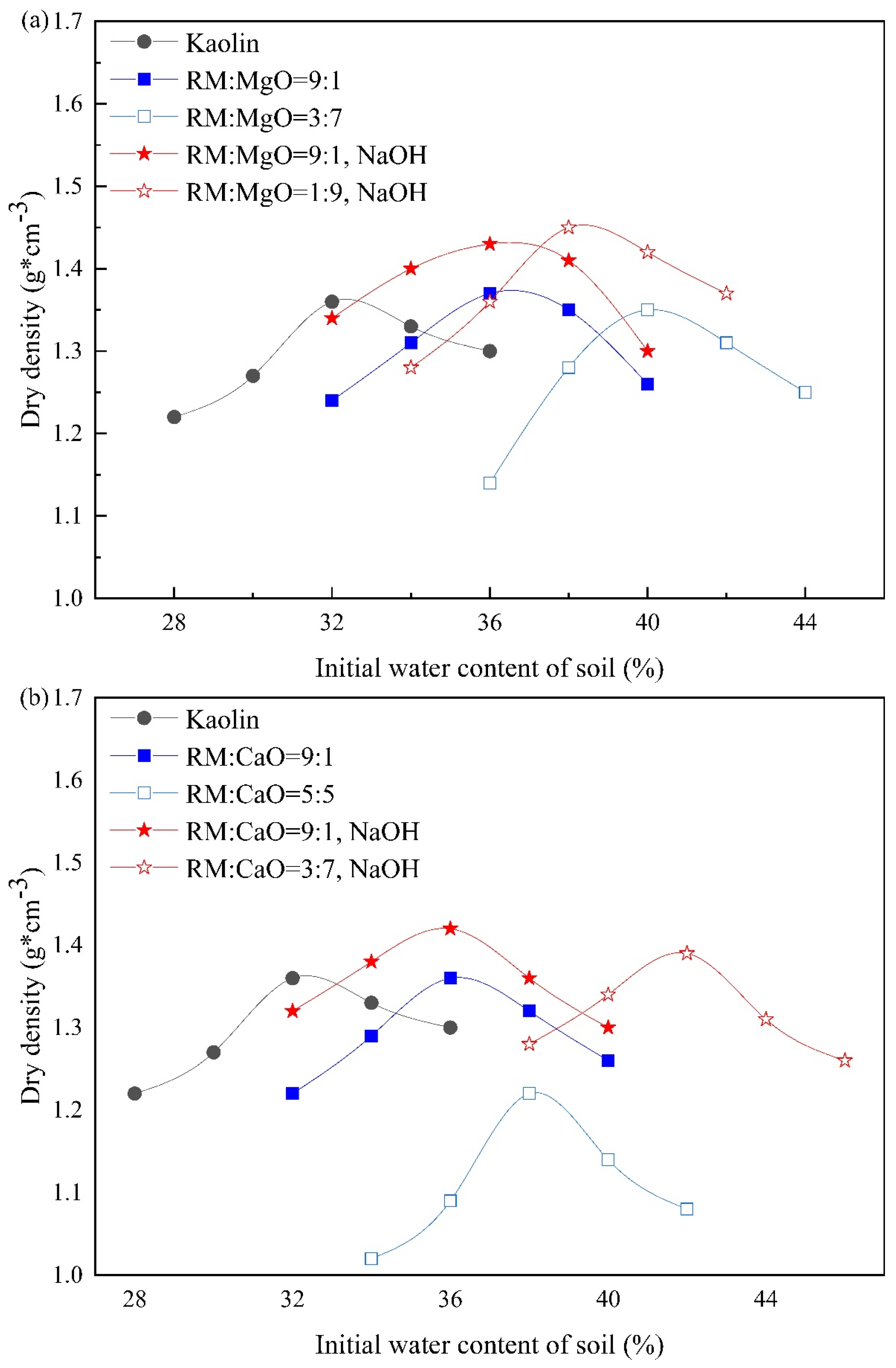
3.2.1. UCS of RM–MgO (or RM–CaO) Stabilized Soil without NaOH
3.2.2. UCS of RM–MgO (or RM–CaO) Stabilized Soil with NaOH
3.3. Physical, Mechanical, and Microstructural Charateristics of Stabilized Soil under Freeze–Thaw Cycles
3.3.1. The Influence of Freeze–Thaw Cycles on Mass Change
3.3.2. The Influence of Freeze–Thaw Cycles on Volume Change
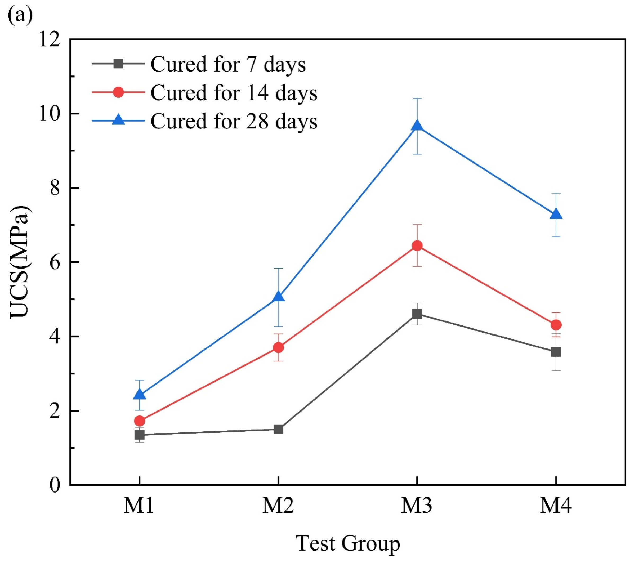
3.3.3. The Influence of Freeze–Thaw Cycles on UCS
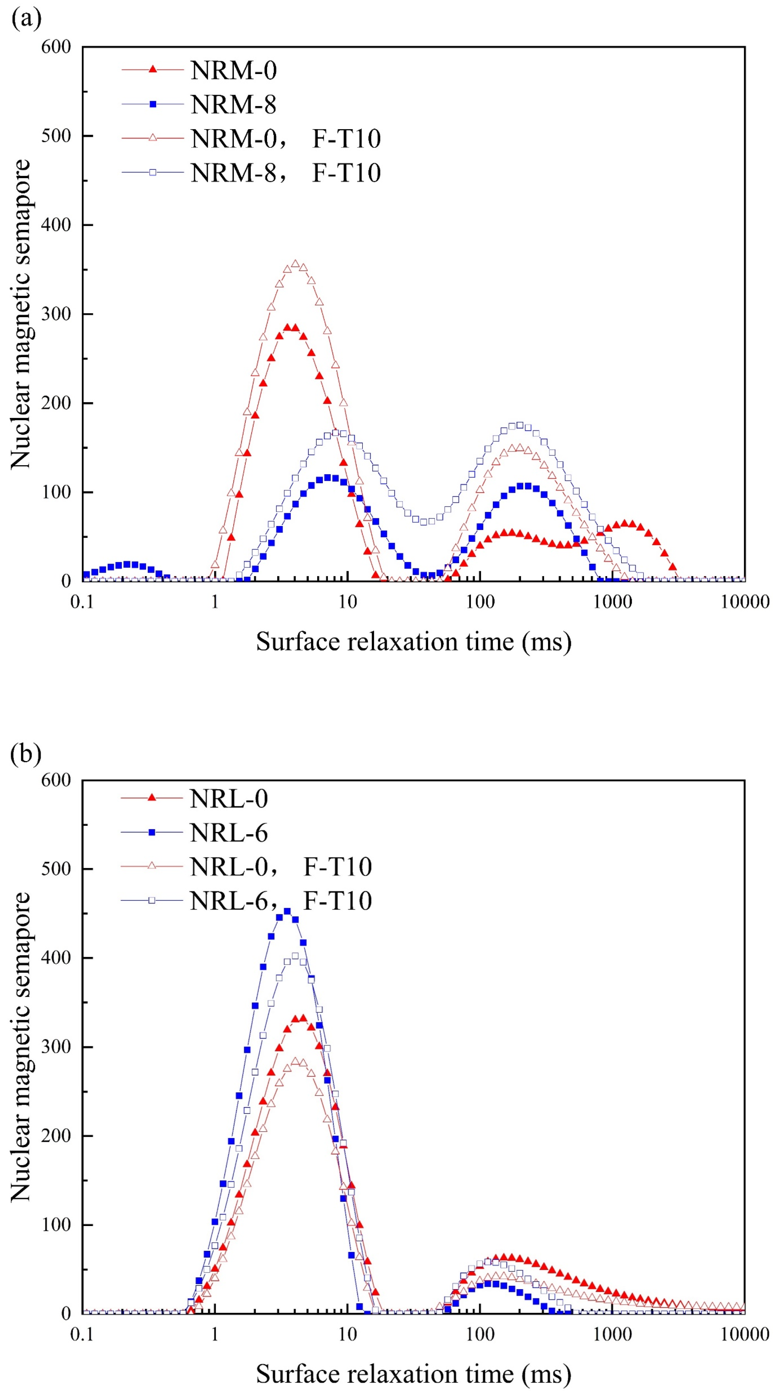
3.3.4. NMR
3.3.5. XRD
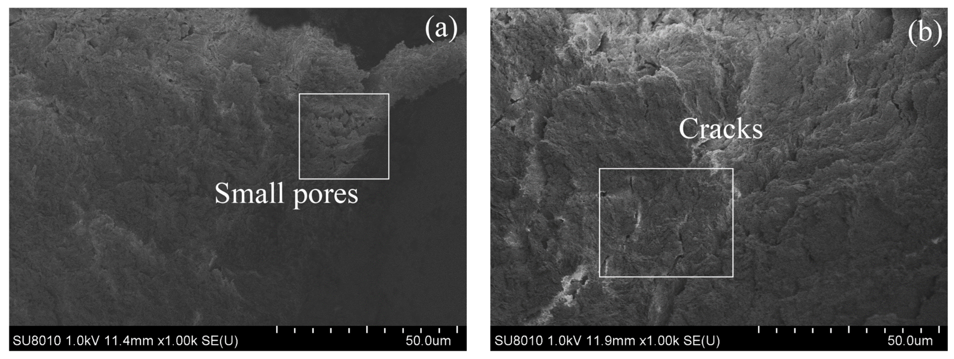
3.3.6. SEM
4. Stabilization Mechanism
5. Conclusions
Author Contributions
Funding
Institutional Review Board Statement
Informed Consent Statement
Data Availability Statement
Conflicts of Interest
References
- Yuan, B.; Yuan, S.; Straub, C.; Chen, W. Activation of binary binder containing fly ash and portland cement using red mud as alkali source and its application in controlled low-strength materials. J. Mater. Civ. Eng. 2020, 32, 04019356. [Google Scholar] [CrossRef]
- Liu, R.-X.; Poon, C.-S. Effects of red mud on properties of self-compacting mortar. J. Cleaner Prod. 2016, 135, 1170–1178. [Google Scholar] [CrossRef]
- Qaidi, S.M.; Tayeh, B.A.; Ahmed, H.U.; Emad, W. A review of the sustainable utilisation of red mud and fly ash for the production of geopolymer composites. Constr. Build. Mater. 2022, 350, 128892. [Google Scholar] [CrossRef]
- Li, W.; Yan, X.; Niu, Z.; Zhu, X. Selective recovery of vanadium from red mud by leaching with using oxalic acid and sodium sulfite. J. Environ. Chem. Eng. 2021, 9, 105669. [Google Scholar] [CrossRef]
- Archambo, M.; Kawatra, S. Red mud: Fundamentals and new avenues for utilization. Miner. Process. Extr. Metall. Rev. 2021, 42, 427–450. [Google Scholar] [CrossRef]
- Liu, W.; Chen, X.; Li, W.; Yu, Y.; Yan, K. Environmental assessment, management and utilization of red mud in China. J. Clean. Prod. 2014, 84, 606–610. [Google Scholar] [CrossRef]
- Li, S.; Zhang, R.; Feng, R.; Hu, B.; Wang, G.; Yu, H. Feasibility of recycling Bayer process red mud for the safety backfill mining of layered soft bauxite under coal seams. Minerals 2021, 11, 722. [Google Scholar] [CrossRef]
- Mi, H.; Yi, L.; Wu, Q.; Xia, J.; Zhang, B. A review of comprehensive utilization of red mud. Waste Manag. Res. 2022, 40, 1594–1607. [Google Scholar] [CrossRef]
- Chavan, S.; Salokhe, S.; Nadagauda, P.; Patil, S.; Mane, K. An investigational study on properties of concrete produced with industrial waste red mud. Mater. Today Proc. 2021, 42, 733–738. [Google Scholar] [CrossRef]
- Kavak, A.; Baykal, G. Long-term behavior of lime-stabilized kaolinite clay. Environ. Earth Sci. 2012, 66, 1943–1955. [Google Scholar] [CrossRef]
- Li, W.; Chen, Y.; Li, R.; Xiao, H.; Li, L.; Yang, J. A new method for carbonating magnesia and its possible application to soil stabilization and CO2 capture. Constr. Build. Mater. 2023, 383, 131263. [Google Scholar] [CrossRef]
- Alam, S.; Das, S.K.; Rao, B.H. Strength and durability characteristic of alkali activated GGBS stabilized red mud as geo-material. Constr. Build. Mater. 2019, 211, 932–942. [Google Scholar] [CrossRef]
- Sahile, K. Utilization of red mud-fly ash reinforced with cement in road construction applications. Adv. Mater. Sci. Eng. 2021, 2021, 3728652. [Google Scholar] [CrossRef]
- Mukiza, E.; Zhang, L.; Liu, X.; Zhang, N. Utilization of red mud in road base and subgrade materials: A review. Resour. Conserv. Recycl. 2019, 141, 187–199. [Google Scholar] [CrossRef]
- Li, R.; Zhang, T.; Liu, Y.; Lv, G.; Xie, L. Calcification–carbonation method for red mud processing. J. Hazard. Mater. 2016, 316, 94–101. [Google Scholar] [CrossRef]
- Fei, J.-C.; Min, X.-B.; Wang, Z.-X.; Pang, Z.-H.; Liang, Y.-J.; Ke, Y. Health and ecological risk assessment of heavy metals pollution in an antimony mining region: A case study from South China. Environ. Sci. Pollut. Res. 2017, 24, 27573–27586. [Google Scholar] [CrossRef]
- Liu, D.-G.; Min, X.-B.; Ke, Y.; Chai, L.-Y.; Liang, Y.-J.; Li, Y.-C.; Yao, L.-W.; Wang, Z.-B. Co-treatment of flotation waste, neutralization sludge, and arsenic-containing gypsum sludge from copper smelting: Solidification/stabilization of arsenic and heavy metals with minimal cement clinker. Environ. Sci. Pollut. Res. 2018, 25, 7600–7607. [Google Scholar] [CrossRef]
- Vigneshwaran, S.; Uthayakumar, M.; Arumugaprabu, V. Development and sustainability of industrial waste-based red mud hybrid composites. J. Cleaner Prod. 2019, 230, 862–868. [Google Scholar] [CrossRef]
- Li, Y.-C.; Min, X.-B.; Ke, Y.; Chai, L.-Y.; Shi, M.-Q.; Tang, C.-J.; Wang, Q.-W.; Liang, Y.-J.; Lei, J.; Liu, D.-G. Utilization of red mud and Pb/Zn smelter waste for the synthesis of a red mud-based cementitious material. J. Hazard. Mater. 2018, 344, 343–349. [Google Scholar] [CrossRef]
- Zhang, J.; Li, S.; Li, Z.; Liu, C.; Gao, Y. Feasibility study of red mud for geopolymer preparation: Effect of particle size fraction. J. Mater. Cycles Waste 2020, 22, 1328–1338. [Google Scholar] [CrossRef]
- Sreelekshmi, S.; Chandran, R.S.; Varghese, S.R.; Raju, T.; Ramaswamy, K. Rheological and strength behaviour of red mud-slag geopolymer composites. IOP Conf. Ser. Mater. Sci. Eng. 2020, 989, 012005. [Google Scholar] [CrossRef]
- Feigl, V.; Anton, A.; Uzigner, N.; Gruiz, K. Red mud as a chemical stabilizer for soil contaminated with toxic metals. Water Air Soil Pollut. 2012, 223, 1237–1247. [Google Scholar] [CrossRef]
- Aswathy, M.; Salini, U.; Gayathri, V. Utility of lime and red mud in clay soil stabilization. Geotech. Charact. Geoenviron. Eng. 2019, 1, 19–26. [Google Scholar] [CrossRef]
- Sridevi, G.; Sahoo, S.; Sen, S. Stabilization of expansive soil with red mud and lime. Ground Improv. Tech. Geosynth. 2019, 2, 259–268. [Google Scholar] [CrossRef]
- Ma, Q.; Duan, W.; Liu, X.; Fang, P.; Chen, R.; Wang, T.; Hao, Z. Engineering Performance Evaluation of Recycled Red Mud Stabilized Loessial Silt as a Sustainable Subgrade Material. Materials 2022, 15, 3391. [Google Scholar] [CrossRef]
- Suo, C.; Yao, X.; Song, Z.; Dong, X. Mechanical and leaching characteristics of red mud residue solidified/stabilized high Cu (II)-contaminated soil. Environ. Earth Sci. 2022, 81, 9. [Google Scholar] [CrossRef]
- Hu, W.; Nie, Q.; Huang, B.; Su, A.; Du, Y.; Shu, X.; He, Q. Mechanical property and microstructure characteristics of geopolymer stabilized aggregate base. Constr. Build. Mater. 2018, 191, 1120–1127. [Google Scholar] [CrossRef]
- Guo, S.; Lu, Z.; Liu, G.; Zhuang, B.; Fan, Y.; Zheng, Z. Influence of Freeze-Thaw Cycles on Mechanical Response of Levee Pavement. Adv. Civ. Eng. 2021, 2021, 6639303. [Google Scholar] [CrossRef]
- Zhou, B.; Sanchez, M.; Shastri, A.; Lee, J. Mechanical Behavior of Soil Subjected to Freezing-Thawing Cycles. PanAm Unsaturated Soils 2017, 2017, 300–307. [Google Scholar] [CrossRef]
- Yang, Z.; Li, X.; Li, D.; Wang, Y.; Liu, X. Effects of long-term repeated freeze-thaw cycles on the engineering properties of compound solidified/stabilized Pb-contaminated soil: Deterioration characteristics and mechanisms. Int. J. Environ. Res. Public Health 2020, 17, 1798. [Google Scholar] [CrossRef]
- Cristelo, N.; Glendinning, S.; Fernandes, L.; Pinto, A.T. Effect of calcium content on soil stabilisation with alkaline activation. Constr. Build. Mater. 2012, 29, 167–174. [Google Scholar] [CrossRef]
- Pavithra, P.; Srinivasula Reddy, M.; Dinakar, P.; Hanumantha Rao, B.; Satpathy, B.; Mohanty, A. Effect of the Na2SiO3/NaOH ratio and NaOH molarity on the synthesis of fly ash-based geopolymer mortar. Geo-Chicago 2016, 2016, 336–344. [Google Scholar] [CrossRef]
- ASTM D698-12e2; Standard Test Methods for Laboratory Compaction Characteristics of Soil Using Standard Effort (12,400 ft-lbf/ft3 (600 kN-m/m3)). ASTM: West Conshohocken, PA, USA, 2012.
- ASTM D1633; Standard Method for Compressive Strength of Molded Soil-Cement Cylinders. ASTM: West Conshohocken, PA, USA, 2017.
- ASTM D2166/D2166M-16; Standard Test Method for Unconfined Compressive Strength of Cohesive Soil. ASTM: West Conshohocken, PA, USA, 2016.
- Chen, R.; Cai, G.; Dong, X.; Mi, D.; Puppala, A.J.; Duan, W. Mechanical properties and micro-mechanism of loess roadbed filling using by-product red mud as a partial alternative. Constr. Build. Mater. 2019, 216, 188–201. [Google Scholar] [CrossRef]
- Zhongping, Y.; Yao, W.; Xuyong, L.; Shupei, R.; Hui, X.; Jiazhuo, C. The effect of long-term freeze-thaw cycles on the stabilization of lead in compound solidified/stabilized lead-contaminated soil. Environ. Sci. Pollut. Res. 2021, 28, 37413–37423. [Google Scholar] [CrossRef]
- Nie, Q.; Hu, W.; Ai, T.; Huang, B.; Shu, X.; He, Q. Strength properties of geopolymers derived from original and desulfurized red mud cured at ambient temperature. Constr. Build. Mater. 2016, 125, 905–911. [Google Scholar] [CrossRef]
- Yi, Y.; Gu, L.; Liu, S.; Jin, F. Magnesia reactivity on activating efficacy for ground granulated blastfurnace slag for soft clay stabilisation. Appl. Clay Sci. 2016, 126, 57–62. [Google Scholar] [CrossRef]
- Millogo, Y.; Hajjaji, M.; Ouedraogo, R. Microstructure and physical properties of lime-clayey adobe bricks. Constr. Build. Mater. 2008, 22, 2386–2392. [Google Scholar] [CrossRef]
- ASTM D4609; Standard Guide for Evaluating the Effectiveness of Admixture for Soil Stabilization. ASTM: West Conshohocken, PA, USA, 2008.
- Zhang, W.; Pi, Y.; Kong, W.; Zhang, Y.; Wu, P.; Zeng, W.; Yang, F. Influence of damage degree on the degradation of concrete under freezing-thawing cycles. Constr. Build. Mater. 2020, 260, 119903. [Google Scholar] [CrossRef]
- Lu, Y.; Liu, S.; Zhang, Y.; Li, Z.; Xu, L. Freeze-thaw performance of a cement-treated expansive soil. Cold Reg. Sci. Technol. 2020, 170, 102926. [Google Scholar] [CrossRef]
- Konrad, J. Physical processes during freeze-thaw cycles in clayey silts. Cold Reg. Sci. Technol. 1989, 16, 291–303. [Google Scholar] [CrossRef]
- Li, G.; Ma, W.; Zhao, S.; Mao, Y.; Mu, Y. Effect of freeze-thaw cycles on mechanical behavior of compacted fine-grained soil. J. Cold Reg. Eng. 2012, 2012, 72–81. [Google Scholar] [CrossRef]
- Dong, J.; Lyu, H.; Xu, G.; He, C. NMR-based study on soil pore structures affected by drying–wetting cycles. Arab. J. Sci. Eng. 2020, 45, 4161–4169. [Google Scholar] [CrossRef]
- He, J.; Zhang, L.; Zhang, C. Durability Analysis of Sludge Solidified with Soda Residue Subjected to Dry-Wet and Freeze-Thaw Cycles. Adv. Civ. Eng. 2021, 2021, 9960416. [Google Scholar] [CrossRef]
- Zheng, Y.; Ma, W.; Mu, Y.; Bing, H. Analysis of soil structures and the mechanisms under the Action of freezing and thawing cycles. J. Cold Reg. Eng. 2015, 2015, 25–33. [Google Scholar] [CrossRef]
- Li, W.; Li, R.; Chen, Y.; Xiao, H. Comparison of Two Sulfate-Bearing Soils Stabilized with Reactive Magnesia-Activated Ground Granulated Blast Furnace Slag: Swelling, Strength, and Mechanism. Buildings 2023, 13, 230. [Google Scholar] [CrossRef]
- Hekal, E.E.; Kishar, E.; Mostafa, H. Magnesium sulfate attack on hardened blended cement pastes under different circumstances. Cement Concrete Res. 2002, 32, 1421–1427. [Google Scholar] [CrossRef]


| Composition | CaO | SiO2 | Fe2O3 | Al2O3 | MgO | Na2O | Others | Loss on Ignition |
|---|---|---|---|---|---|---|---|---|
| Kaolin | 0.06 | 53.59 | 0.89 | 43.24 | 0.05 | 0.07 | 2.10 | 0 |
| RM | 8.22 | 27.33 | 26.08 | 20.95 | 1.23 | 9.61 | 6.58 | 0 |
| MgO | 5.62 | 10.23 | 0.03 | 6.34 | 76.72 | 0.27 | 0.79 | 0 |
| CaO | 92.58 | 1.87 | 0.36 | 1.30 | 3.10 | 0.15 | 0.62 | 0.02 |
| Test Group No. | Water–Binder Ratio | RM (%) | MgO (%) | CaO (%) | Days of Curing |
|---|---|---|---|---|---|
| M-1 | 0.5 | 75 | 25 | 0 | 7, 14, 28 |
| M-2 | 60 | 40 | 0 | ||
| M-3 | 43 | 57 | 0 | ||
| M-4 | 33 | 67 | 0 | ||
| L-1 | 75 | 0 | 25 | ||
| L-2 | 60 | 0 | 40 | ||
| L-3 | 50 | 0 | 50 | ||
| L-4 | 43 | 0 | 57 |
| Test Group No. | RM (%) | MgO (%) | CaO (%) | NaOH (mol/L) | Days of Curing |
|---|---|---|---|---|---|
| RM-1 | 90 | 10 | 0 | 0 | 7, 14, 28 |
| RM-2 | 80 | 20 | 0 | 0 | |
| RM-3 | 70 | 30 | 0 | 0 | |
| RM-4 | 60 | 40 | 0 | 0 | |
| RM-5 | 50 | 50 | 0 | 0 | |
| RM-6 | 40 | 60 | 0 | 0 | |
| RM-7 | 30 | 70 | 0 | 0 | |
| NRM-1 | 90 | 10 | 0 | 1.25 | |
| NRM-2 | 80 | 20 | 0 | 1.25 | |
| NRM-3 | 70 | 30 | 0 | 1.25 | |
| NRM-4 | 60 | 40 | 0 | 1.25 | |
| NRM-5 | 50 | 50 | 0 | 1.25 | |
| NRM-6 | 40 | 60 | 0 | 1.25 | |
| NRM-7 | 30 | 70 | 0 | 1.25 | |
| NRM-8 | 20 | 80 | 0 | 1.25 | |
| NRM-9 | 10 | 90 | 0 | 1.25 | |
| NRM-0 | 0 | 100 | 0 | 1.25 | |
| RL-1 | 90 | 0 | 10 | 0 | |
| RL-2 | 80 | 0 | 20 | 0 | |
| RL-3 | 70 | 0 | 30 | 0 | |
| RL-4 | 60 | 0 | 40 | 0 | |
| RL-5 | 50 | 0 | 50 | 0 | |
| NRL-1 | 90 | 0 | 10 | 1.25 | |
| NRL-2 | 80 | 0 | 20 | 1.25 | |
| NRL-3 | 70 | 0 | 30 | 1.25 | |
| NRL-4 | 60 | 0 | 40 | 1.25 | |
| NRL-5 | 50 | 0 | 50 | 1.25 | |
| NRL-6 | 40 | 0 | 60 | 1.25 | |
| NRL-7 | 30 | 0 | 70 | 1.25 | |
| NRL-0 | 0 | 0 | 100 | 1.25 |
Disclaimer/Publisher’s Note: The statements, opinions and data contained in all publications are solely those of the individual author(s) and contributor(s) and not of MDPI and/or the editor(s). MDPI and/or the editor(s) disclaim responsibility for any injury to people or property resulting from any ideas, methods, instructions or products referred to in the content. |
© 2024 by the authors. Licensee MDPI, Basel, Switzerland. This article is an open access article distributed under the terms and conditions of the Creative Commons Attribution (CC BY) license (https://creativecommons.org/licenses/by/4.0/).
Share and Cite
Li, W.; Huang, K.; Chen, F.; Li, L.; Cheng, Y.; Yang, K. Engineering Properties and Microstructure of Soils Stabilized by Red-Mud-Based Cementitious Material. Materials 2024, 17, 2340. https://doi.org/10.3390/ma17102340
Li W, Huang K, Chen F, Li L, Cheng Y, Yang K. Engineering Properties and Microstructure of Soils Stabilized by Red-Mud-Based Cementitious Material. Materials. 2024; 17(10):2340. https://doi.org/10.3390/ma17102340
Chicago/Turabian StyleLi, Wentao, Ke Huang, Feng Chen, Lihua Li, Yang Cheng, and Kang Yang. 2024. "Engineering Properties and Microstructure of Soils Stabilized by Red-Mud-Based Cementitious Material" Materials 17, no. 10: 2340. https://doi.org/10.3390/ma17102340
APA StyleLi, W., Huang, K., Chen, F., Li, L., Cheng, Y., & Yang, K. (2024). Engineering Properties and Microstructure of Soils Stabilized by Red-Mud-Based Cementitious Material. Materials, 17(10), 2340. https://doi.org/10.3390/ma17102340