
Axial Tensile Ultimate Strength of an Unbonded Flexible Riser Based on a Numerical Method

Abstract
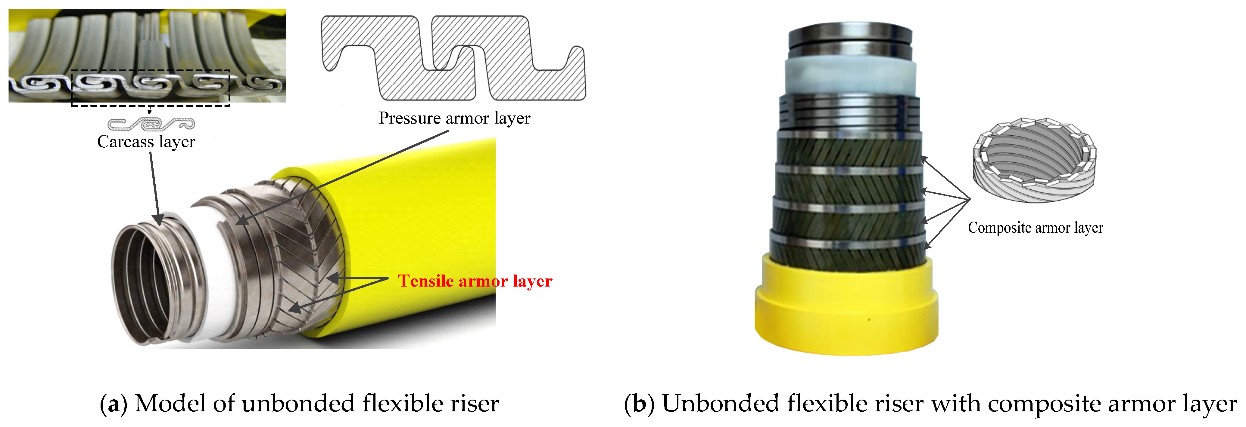
1. Introduction
2. Theoretical Formulations
- The external load on an unbonded flexible riser can be decoupled into axisymmetric loads and bending moment;
- When studying the cross-sectional mechanical properties of an unbonded flexible riser, all consisted layers are assumed to be in the small deformation stage and we neglect the material nonlinearity;
- The riser has a sufficient length (L/D 10, where L is the initial length of the riser and D is the outer diameter of the riser), and the end-effect is neglected;
- The effect of the bending stiffener is neglected and the initial imperfection of the riser is also neglected; we assume that each layer of the riser has the same axial elongation and torsion angle along the central axis;
- For helical layers, the frictional energy by the slippage of the helical tendon is neglected;
- The anti-friction layer is simplified as a cylindrical layer;
- The thickness deformation of the carcass layer, as well as the pressure armor layer, is neglected;
- When studying the fracture of the tensile armor layer, we consider that the tensile armor layer loses its bearing capacity when it reaches the yield stress.
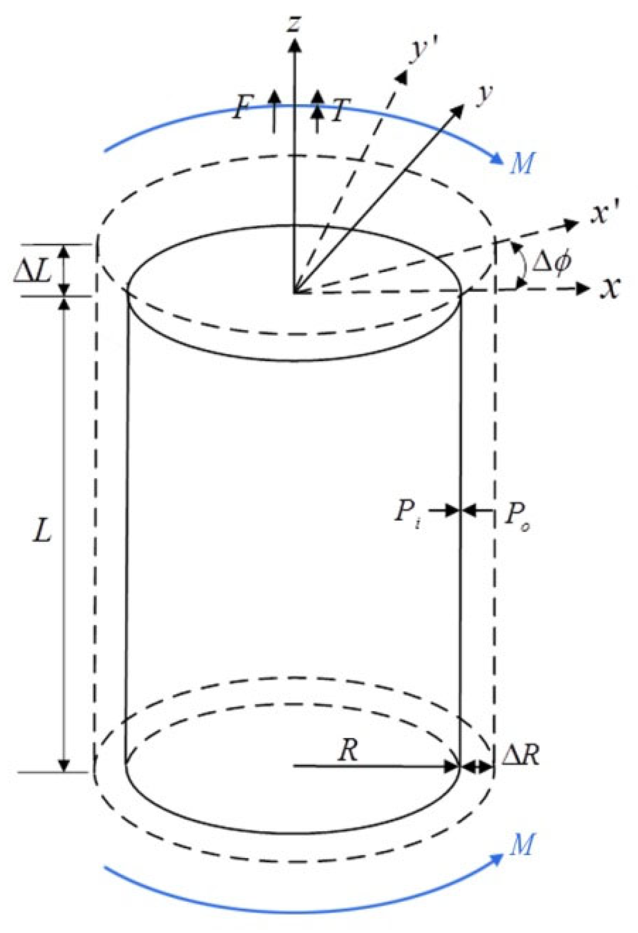
2.1. Theoretical Model of Cylindrical Layer under Axisymmetric Loads
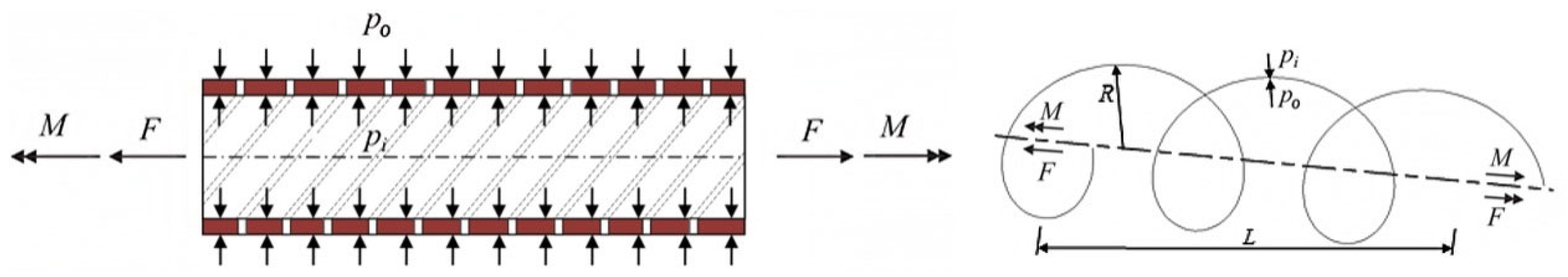
2.2. Theoretical Model of Helical Layer under Axisymmetric Loads
2.3. Geometric Relationship between Adjacent Layers
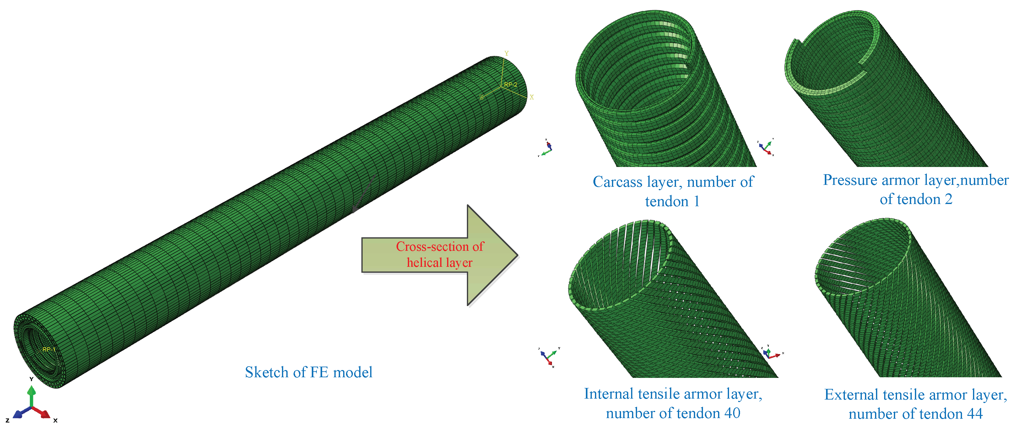
3. Numerical Simulation
4. Model Verification
5. Discussion
5.1. Fracture Failure of Tensile Armor Layer under Axial Tension
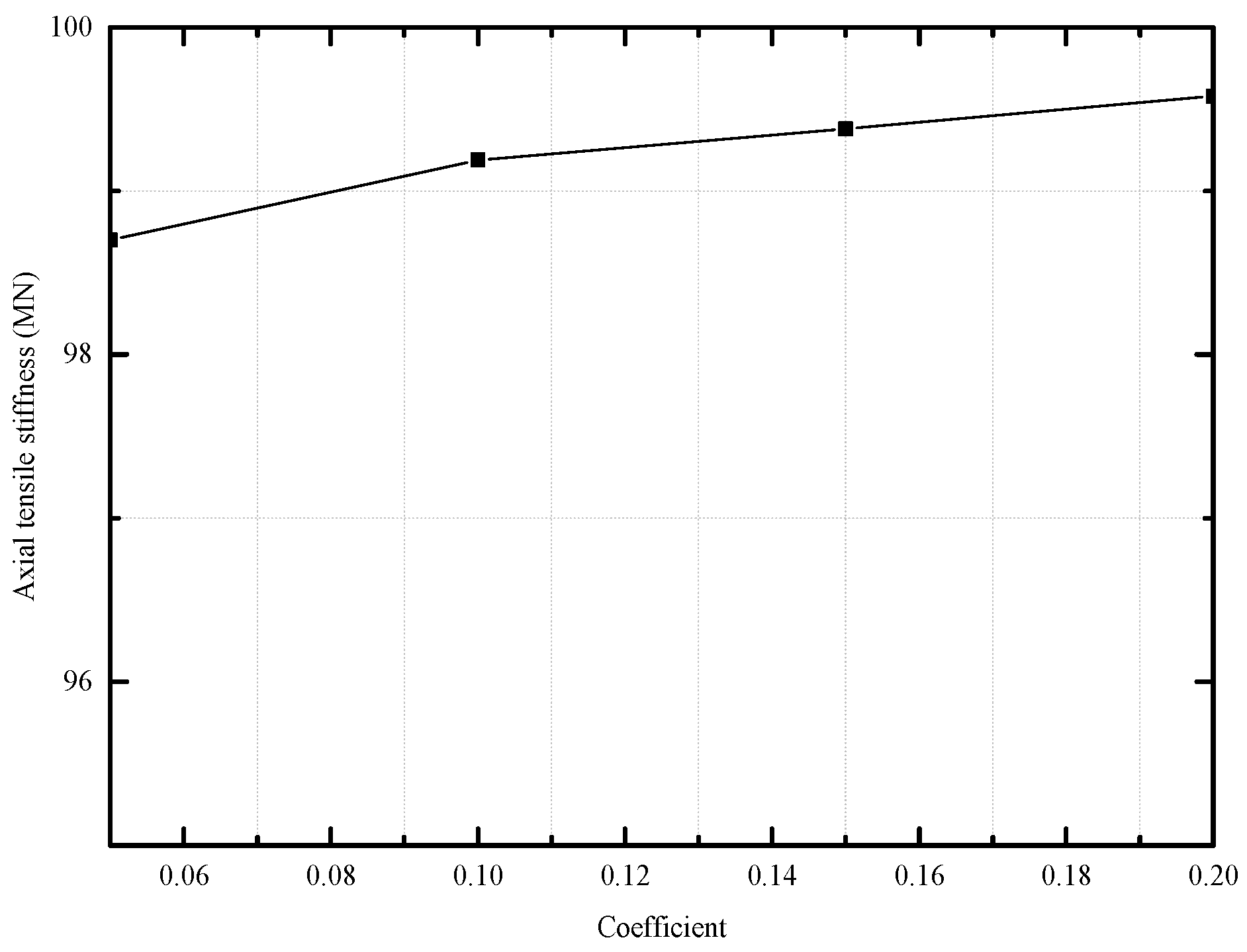
5.2. Effect of Frictional Coefficient on the Axial Tensile Stiffness
6. Conclusions
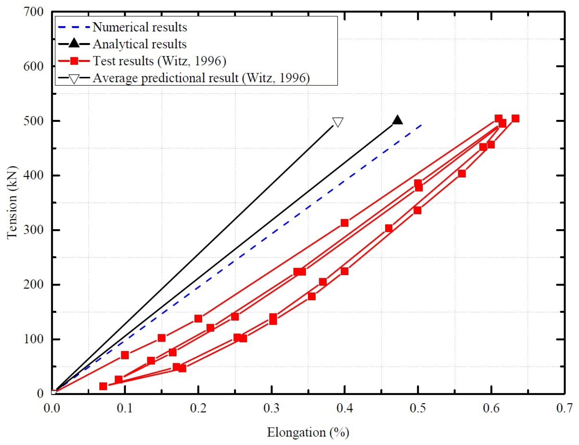
- The self-locking structures of the carcass layer and pressure armor layer have little effect on the axial tensile stiffness and axial tensile strength of an unbonded flexible riser. The proposed numerical method, due to its ability to model the complex geometric and contact behavior within unbonded flexible risers, is closer to the test results compared to the analytical results. But there is still a relative deviation of 8.07% between the numerical and the experimental results, since there always exists initial pre-stress in the actual riser due to the manufacturing process, and the detailed frictional coefficient is also unknown for the experimental measurement.
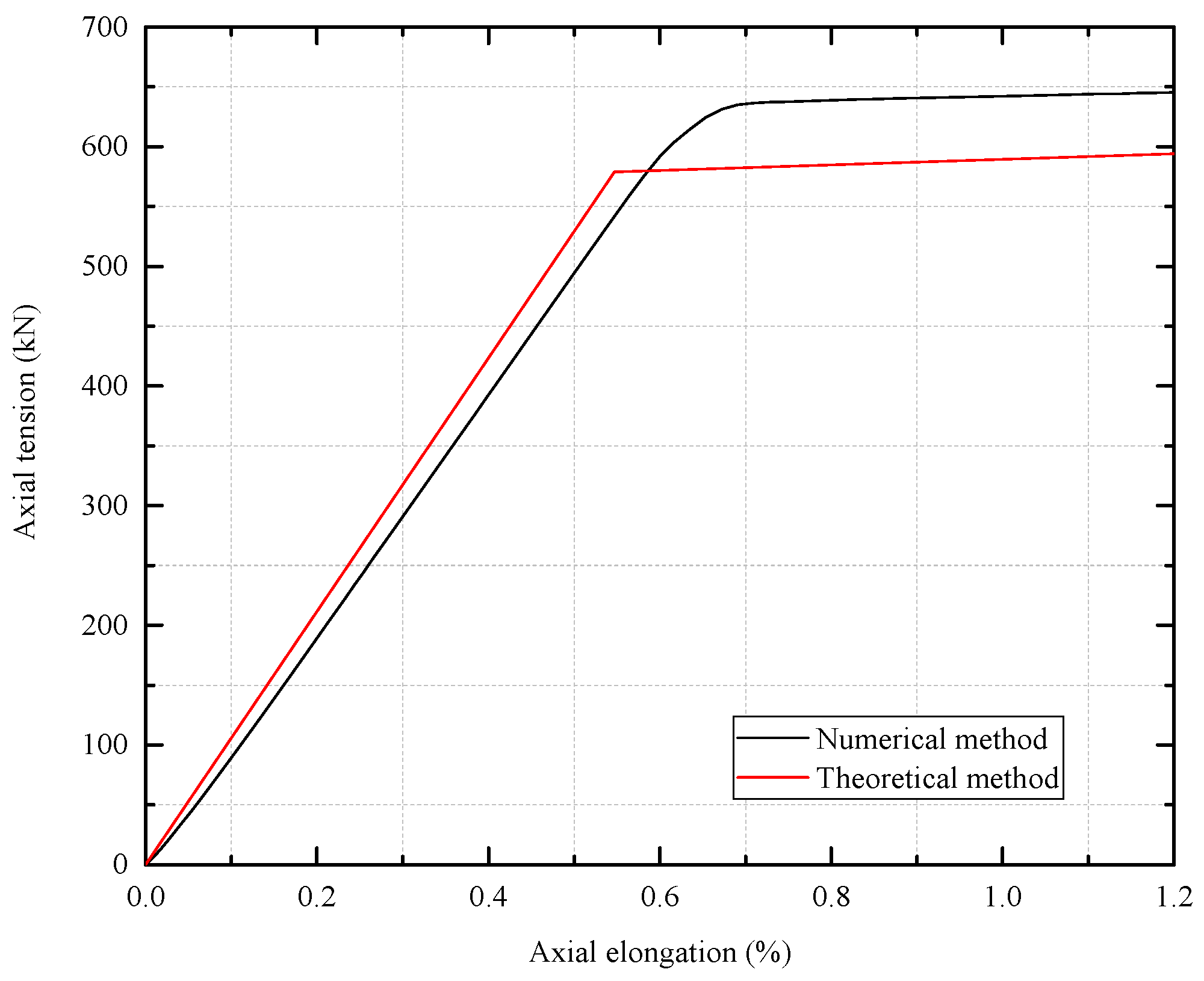
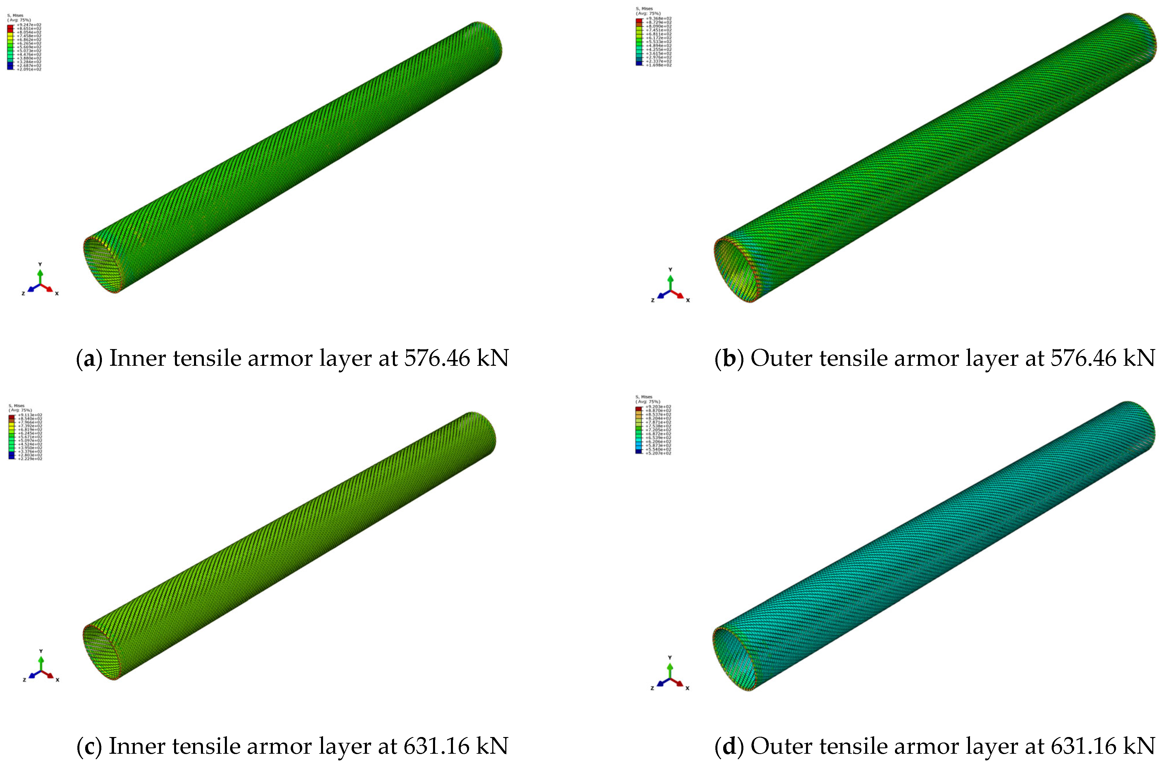
- In the inner tensile armor layer, the fracture would occur first before the outer tensile armor layer. The numerical method agrees well with the theoretical method, and the corresponding relative deviation is only 2.76%. The axial tensile stiffness of an unbonded flexible riser model would decrease sharply when fracture occurs in the tensile armor layer, and the unbonded flexible riser loses bearing capacity when both tensile armor layers reach yield stress.
- The effect of the friction coefficient on the tensile behavior can well explain the relative deviations of numerical, analytical and experimental methods. The increasing friction coefficient can improve the axial tensile stiffness of an unbonded flexible riser. When the friction coefficient is infinite, the numerical simulation remains consistent with the theoretical assumption that no interlayer slip occurs, and the larger the friction coefficient, the closer it is to the theoretical result. When completely neglecting the interlayer friction, the helical tendon can move freely under the external axial tension, similar to the hysteresis during test measurements, and the corresponding axial tensile stiffness is also consistent with the test results.
Author Contributions
Funding
Institutional Review Board Statement
Informed Consent Statement
Data Availability Statement
Conflicts of Interest
References
- Malta, E.R.; Martins, C.A. Finite element analysis of flexible pipes under compression. In Proceedings of the International Conference on Offshore Mechanics and Arctic Engineering, San Francisco, CA, USA, 8–13 June 2014; Volume 45462, p. V06AT04A010. [Google Scholar]
- Epsztein, T.; Demanze, F.; Lefebvre, X.; Jarrin, J. New anti H2S layer for flexible pipes. In Proceedings of the Offshore Technology Conference, Houston, TX, USA, 2–5 May 2011; p. OTC 21371. [Google Scholar]
- Rytter, J. Qualification approach to unbonded flexible pipes with fibre reinforced armour layer. In Proceedings of the International Conference on Offshore Mechanics and Arctic Engineering, Vancouver, BC, Canada, 20–25 June 2004; Volume 37440, pp. 757–765. [Google Scholar]
- Lambert, A.; Do, A.T.; Felix-Henry, A.; Grosjean, F. Qualification of unbonded dynamic riser with carbon fiber composite armours. In Proceedings of the International Conference on Offshore Mechanics and Arctic Engineering, Rio de Janeiro, Brazil, 1–6 July 2012; Volume 44908, pp. 117–125. [Google Scholar]
- Kalman, M.D.; Yu, L.; Seymour, M.; Erni, J. Qualification of composite armor materials for unbonded flexible pipe. In Proceedings of the Offshore Technology Conference, Houston, TX, USA, 30 April–3 May 2012; p. OTC-23185-MS. [Google Scholar]
- Liu, Q.; Xue, H.; Tang, W. Theoretical and numerical methods to predict the behavior of unbonded flexible riser with composite armor layers subjected to axial tension. Ocean. Eng. 2020, 199, 107038. [Google Scholar] [CrossRef]
- Féret, J.J.; Bournazel, C.L. Calculation of stresses and slip in structural layers of unbonded flexible pipes. J. Offshore Mech. Arct. Eng. 1987, 109, 263–269. [Google Scholar] [CrossRef]
- Berge, S.; Engseth, A.; Fylling, I.; Leira, B.J.; Nygaard, I.; Larsen, C.M.; Olufsen, A. Handbook on Design and Operation of Flexible Pipes, STF70 A92006; SINTEF: Trondheim, Norway, 1992. [Google Scholar]
- Kebadze, E. Theoretical Modelling of Unbonded Flexible Pipe Cross-Sections. Ph.D. Thesis, South Bank University, London, UK, 2000. [Google Scholar]
- Kraincani, I.; Kebadze, E. Slip initiation and progression in helical armouring layers of unbonded flexible pipes and its effect on pipe bending behaviour. J. Strain Anal. Eng. Des. 2001, 36, 265–275. [Google Scholar] [CrossRef]
- Dong, L.; Huang, Y.; Zhang, Q.; Liu, G. An analytical model to predict the bending behavior of unbonded flexible pipes. J. Ship Res. 2013, 57, 171–177. [Google Scholar] [CrossRef]
- Sathikh, S.; Moorthy MB, K.; Krishnan, M. A symmetric linear elastic model for helical wire strands under axisymmetric loads. J. Strain Anal. Eng. Des. 1996, 31, 389–399. [Google Scholar] [CrossRef]
- Karathanasopoulos, N.; Ganghoffer, J.F.; Papailiou, K.O. Analytical closed-form expressions for the structural response of helical constructions to thermal loads. Int. J. Mech. Sci. 2016, 117, 258–264. [Google Scholar] [CrossRef]
- Dai, T.; Sævik, S.; Ye, N. An anisotropic friction model in non-bonded flexible risers. Mar. Struct. 2018, 59, 423–443. [Google Scholar] [CrossRef]
- Dai, T.; Sævik, S.; Ye, N. Friction models for evaluating dynamic stresses in non-bonded flexible risers. Mar. Struct. 2017, 55, 137–161. [Google Scholar] [CrossRef]
- Yun, R.; Jang, B.; Kim, J. Improvement of the bending behavior of a flexible riser: Part I—Nonlinear bending behavior considering the shear deformation of polymer layers. Appl. Ocean Res. 2020, 101, 102204. [Google Scholar] [CrossRef]
- Giner, E.; Sukumar, N.; Tarancon, J.E. An Abaqus implementation of the extended finite element method. Eng. Fract. Mech. 2009, 76, 347–368. [Google Scholar] [CrossRef]
- Shahzamanian, M.M.; Lin, M.; Kainat, M.; Yoosef-Ghodsi, N.; Adeeb, S. Systematic literature review of the application of extended finite element method in failure prediction of pipelines. J. Pipeline Sci. Eng. 2021, 1, 241–251. [Google Scholar] [CrossRef]
- Ribeiro, E.J.; de Sousa, J.R.; Ellwanger, G.; Lima, E. On the tension-compression behaviour of flexible risers. In Proceedings of the Thirteenth International Offshore and Polar Engineering Conference, Honolulu, HI, USA, 25–30 May 2003; pp. 105–112. [Google Scholar]
- Sousa, J.R.M.; Magluta, C.; Roitman, N.; Ellwanger, G.B.; Lima, E.C.; Papaleo, A. On the response of flexible risers to loads imposed by hydraulic collars. Appl. Ocean Res. 2009, 31, 157–170. [Google Scholar] [CrossRef]
- Bahtui, A. Development of a Constitutive Model to Simulate Unbonded Flexible Riser Pipe Elements. Ph.D. Thesis, Department of Mechanical Engineering Brunel University, London, UK, 2008. [Google Scholar]
- Bahtui, A.; Bahai, H.; Alfano, G. Numerical and analytical modeling of unbonded flexible risers. J. Offshore Mech. Arct. Eng. 2009, 131, 021401. [Google Scholar] [CrossRef]
- Ren, S.F.; Tang, W.Y.; Guo, J.T. Behavior of unbonded flexible risers subject to axial tension. China Ocean Eng. 2014, 28, 249–258. [Google Scholar] [CrossRef]
- Ren, S.F.; Xue, H.X.; Tang, W.Y. Analytical and numerical models to predict the behavior of unbonded flexible risers under torsion. China Ocean Eng. 2016, 28, 243–256. [Google Scholar] [CrossRef]
- Zhang, M.; Chen, X.; Fu, S.; Guo, Y.; Ma, L. Theoretical and numerical analysis of bending behavior of unbonded flexible risers. Mar. Struct. 2015, 44, 311–325. [Google Scholar] [CrossRef]
- Yoo, D.H.; Jang, B.S.; Yim, K.H. Nonlinear finite element analysis of failure modes and ultimate strength of flexible pipes. Mar. Struct. 2017, 54, 50–72. [Google Scholar] [CrossRef]
- Yoo, D.H.; Jang, B.S.; Yun, R.H. A simplified multi-layered finite element model for flexible pipes. Mar. Struct. 2019, 63, 117–137. [Google Scholar] [CrossRef]
- Liu, Q.S.; Xue, H.X.; Tang, W.Y. Behavior of unbonded flexible riser with composite armor layers under coupling loads. Ocean Eng. 2021, 239, 109907. [Google Scholar] [CrossRef]
- Lu, H.; Vaz, M.A.; Caire, M. Alternative analytical and finite element models for unbonded flexible pipes under axisymmetric loads. Ocean Eng. 2021, 225, 108766. [Google Scholar] [CrossRef]
- Tang, L.; He, W.; Zhu, X.; Zhou, Y. Mechanical analysis of unbonded flexible pipe tensile armor under combined loads. Int. J. Press. Vessel. Pip. 2019, 171, 217–223. [Google Scholar] [CrossRef]
- Ebrahimi, A.; Kenny, S.; Hussein, A. Finite element investigation on the tensile armor wire response of flexible pipe for axisymmetric loading conditions using an implicit solver. J. Offshore Mech. Arct. Eng. 2018, 140, 041402. [Google Scholar] [CrossRef]
- Rahmati, M.T.; Norouzi, S.; Bahai, H.; Alfano, G. Experimental and numerical study of structural behavior of a flexible riser model. Appl. Ocean Res. 2017, 67, 162–168. [Google Scholar] [CrossRef]
- Liu, Q.; Xue, H.; Liu, X.; Tang, W. Failure characteristic analysis of tensile armour layer of unbonded flexible riser under axial compression. Ships Offshore Struct. 2019, 14, 187–198. [Google Scholar] [CrossRef]
- Ramos, R., Jr.; Pesce, C.P.; Roveri, F.E. Some further studies on the axial-torsional behavior of flexible risers. J. Offshore Mech. Arct. Eng. 2014, 136, 81–96. [Google Scholar] [CrossRef]
- Ramos, R., Jr.; Kawano, A. Local structural analysis of flexible pipes subjected to traction, torsion and pressure loads. Mar. Struct. 2015, 42, 95–114. [Google Scholar] [CrossRef]
- Witz, J.A. A case study in the cross-section analysis of flexible risers. Mar. Struct. 1996, 9, 885–904. [Google Scholar] [CrossRef]
- Sævik, S.; Berge, S. Fatigue testing and theoretical studies of two 4 in flexible pipes. Eng. Struct. 1995, 17, 276–292. [Google Scholar] [CrossRef]


| Layer Number | Layer Type | Section Size (mm2) | Number of Tendons | Inner Radius (mm) | Outer Radius (mm) | Laying Angle (°) | Material | Young’s Modulus (GPa) | Poisson’s Ratio |
|---|---|---|---|---|---|---|---|---|---|
| 1 | Carcass | 19.60 | 1 | 31.60 | 35.10 | −87.5 | AISI 304 | 205 | 0.29 |
| 2 | Pressure sheath | - | - | 35.10 | 40.00 | - | Nylon 12 | 0.28 | 0.30 |
| 3 | Zeta layer | 5.55 | 1 | 40.05 | 46.25 | −85.5 | FI-15 | 205 | 0.29 |
| 4 | Anti-friction layer | - | - | 46.25 | 47.75 | - | Nylon 11 | 0.30 | 0.30 |
| 5 | Inner tensile armor layer | 18.00 | 40 | 47.75 | 50.75 | −35.0 | FI-41 | 205 | 0.29 |
| 6 | Anti-friction layer | - | - | 50.75 | 52.25 | - | Nylon 11 | 0.30 | 0.30 |
| 7 | Outer tensile armor layer | 18.00 | 44 | 52.25 | 55.25 | 35.0 | FI-41 | 205 | 0.29 |
| 8 | Fabric tape | 4.50 | - | 55.25 | 55.75 | - | - | 0.60 | 0.30 |
| Method | Axial Tensile Stiffness (MN) | Relative Deviation (%) |
|---|---|---|
| Analytical method | 105.88 | 14.18 |
| Numerical method | 99.19 | 8.07 |
| Experimental method | 91.19 | - |
Disclaimer/Publisher’s Note: The statements, opinions and data contained in all publications are solely those of the individual author(s) and contributor(s) and not of MDPI and/or the editor(s). MDPI and/or the editor(s) disclaim responsibility for any injury to people or property resulting from any ideas, methods, instructions or products referred to in the content. |
© 2024 by the authors. Licensee MDPI, Basel, Switzerland. This article is an open access article distributed under the terms and conditions of the Creative Commons Attribution (CC BY) license (https://creativecommons.org/licenses/by/4.0/).
Share and Cite
Li, D.; Jiang, W.; Xing, Q.; Liu, Q. Axial Tensile Ultimate Strength of an Unbonded Flexible Riser Based on a Numerical Method. Materials 2024, 17, 2286. https://doi.org/10.3390/ma17102286
Li D, Jiang W, Xing Q, Liu Q. Axial Tensile Ultimate Strength of an Unbonded Flexible Riser Based on a Numerical Method. Materials. 2024; 17(10):2286. https://doi.org/10.3390/ma17102286
Chicago/Turabian StyleLi, Dongya, Wanchao Jiang, Qingqing Xing, and Qingsheng Liu. 2024. "Axial Tensile Ultimate Strength of an Unbonded Flexible Riser Based on a Numerical Method" Materials 17, no. 10: 2286. https://doi.org/10.3390/ma17102286
APA StyleLi, D., Jiang, W., Xing, Q., & Liu, Q. (2024). Axial Tensile Ultimate Strength of an Unbonded Flexible Riser Based on a Numerical Method. Materials, 17(10), 2286. https://doi.org/10.3390/ma17102286