

Identification of the Domain Structure Defects of a Radially Magnetized Rubber–Ferritic Conglomerate


Abstract
:1. Introduction
2. Measurement Method
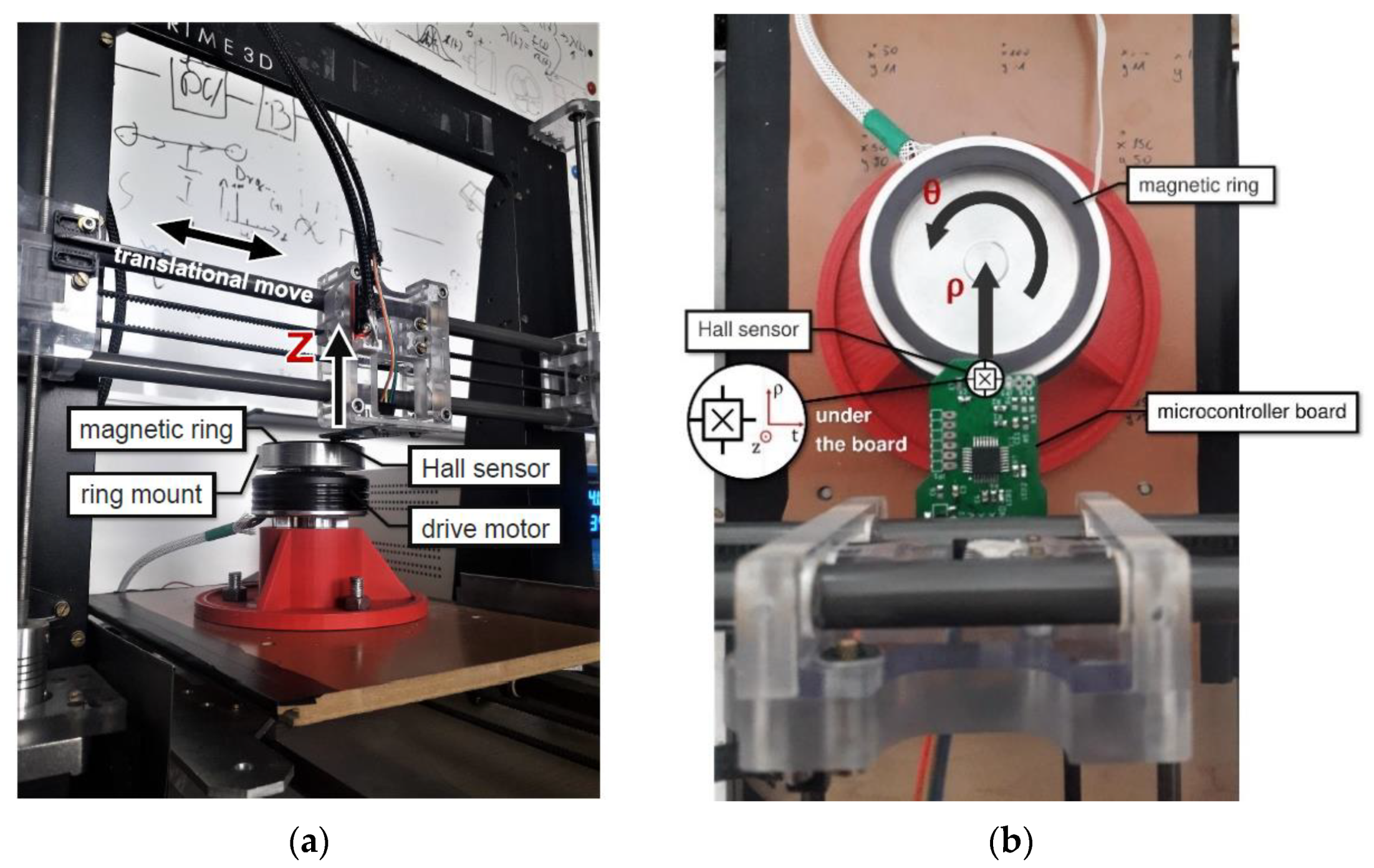
2.1. Hardware and Software Architecture of the Stand
2.2. Experiment
3. Measurement Results
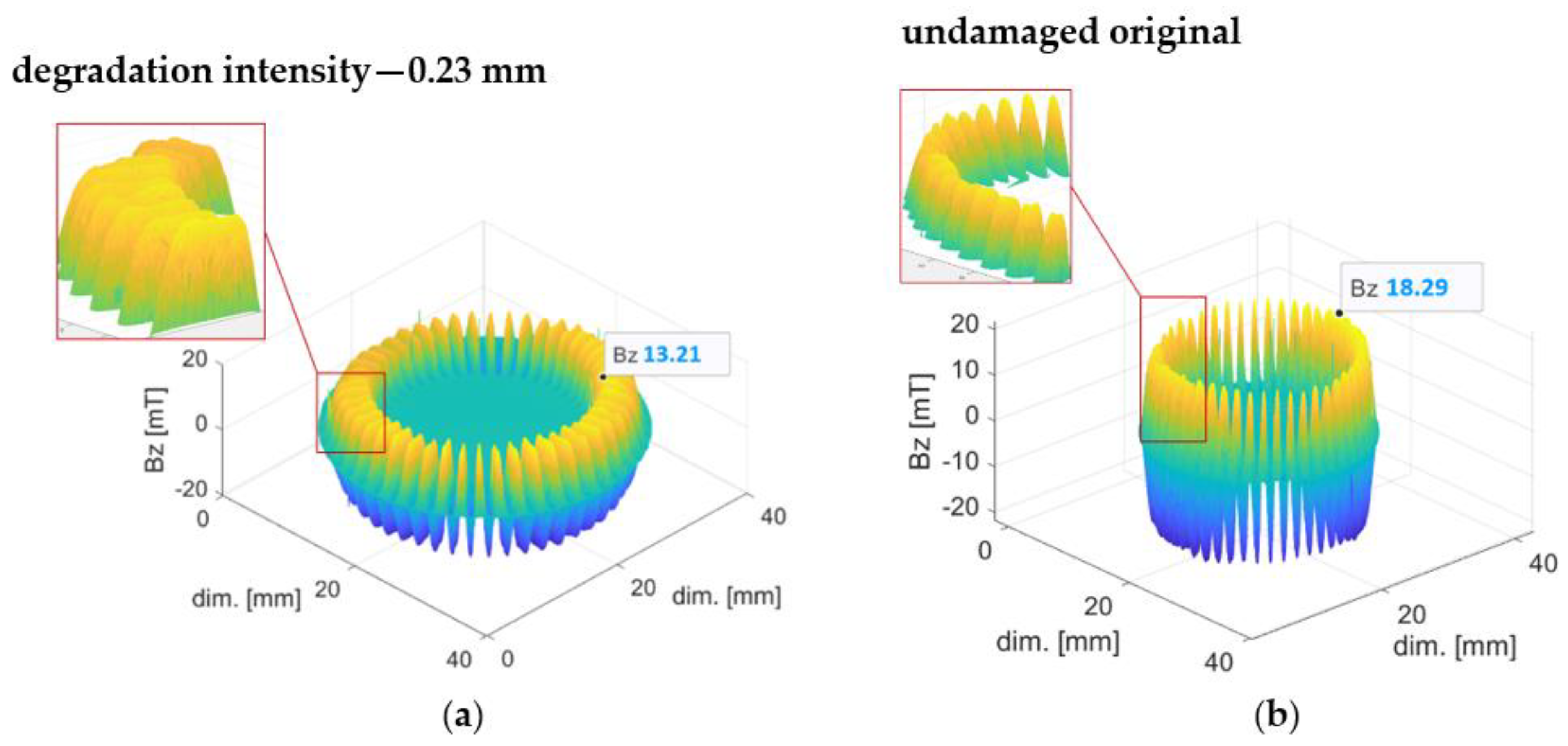
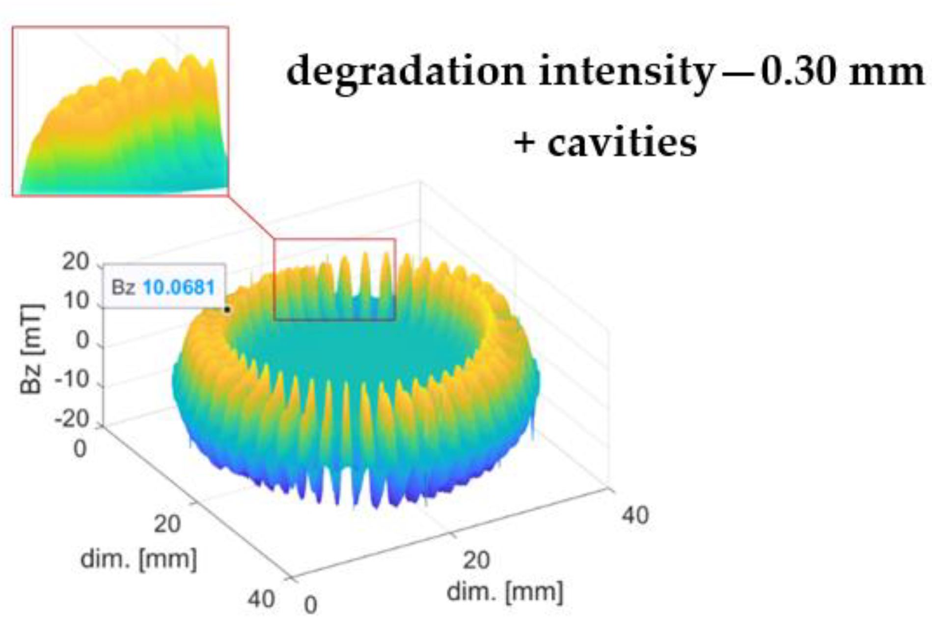
3.1. Mechanical Degradation
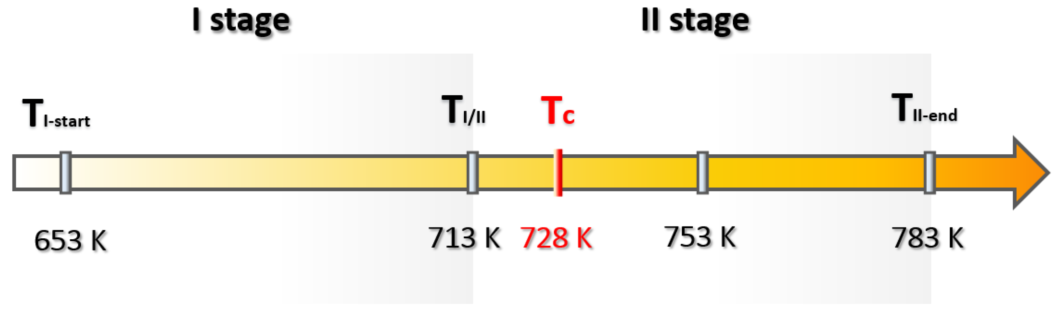
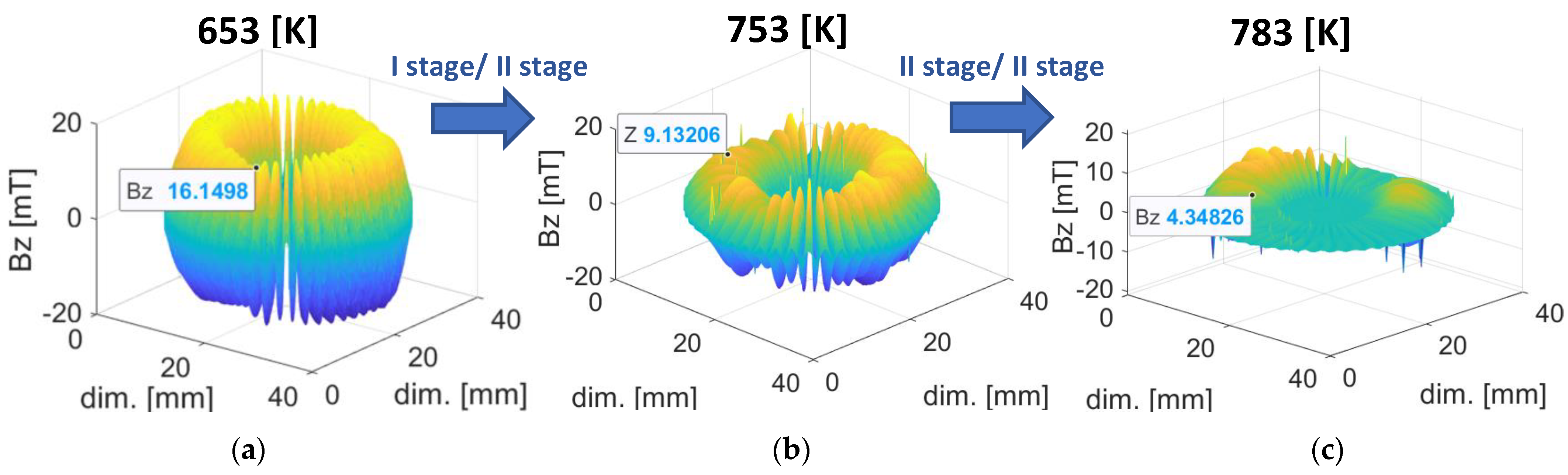
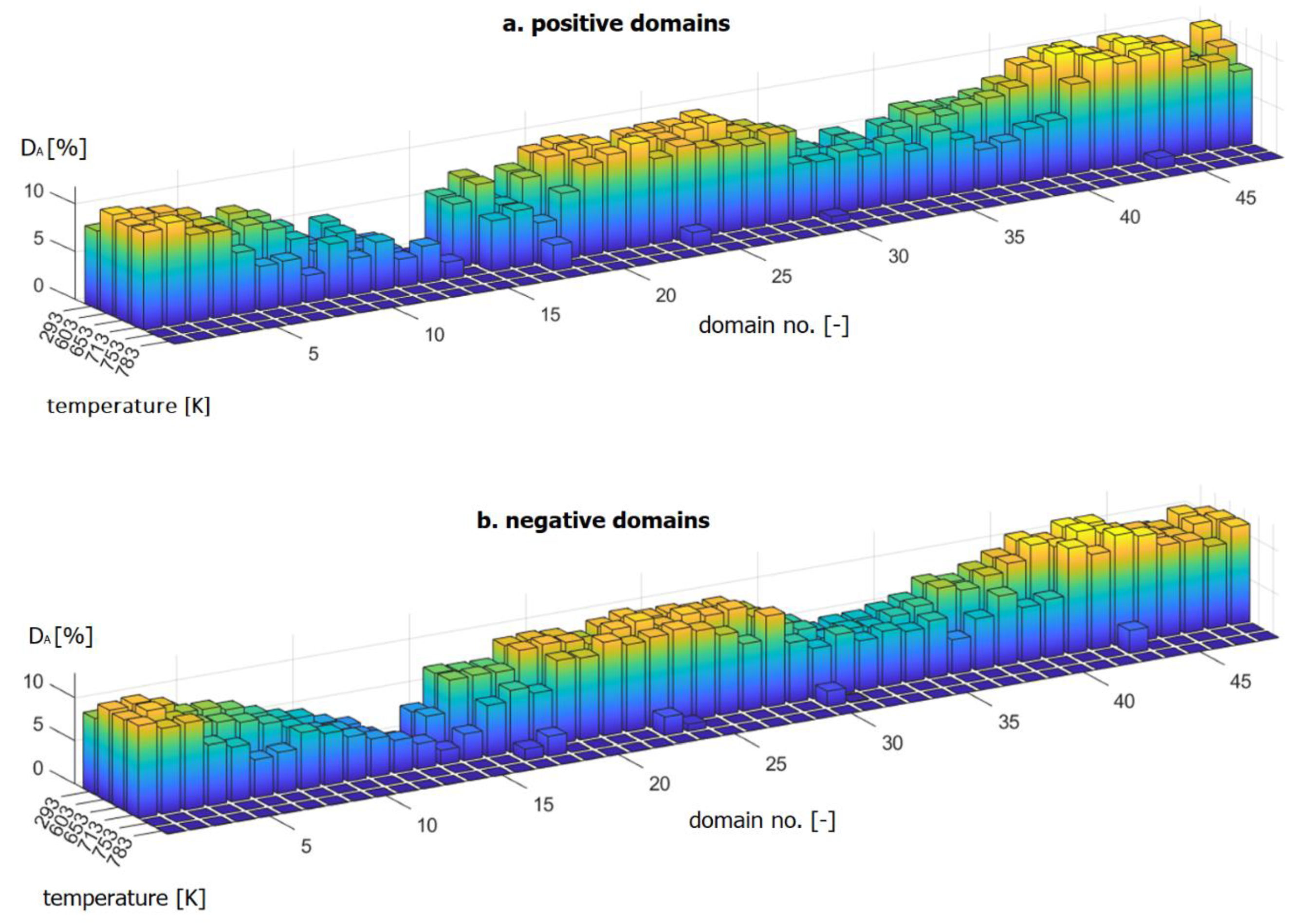
3.2. Thermal Degradation
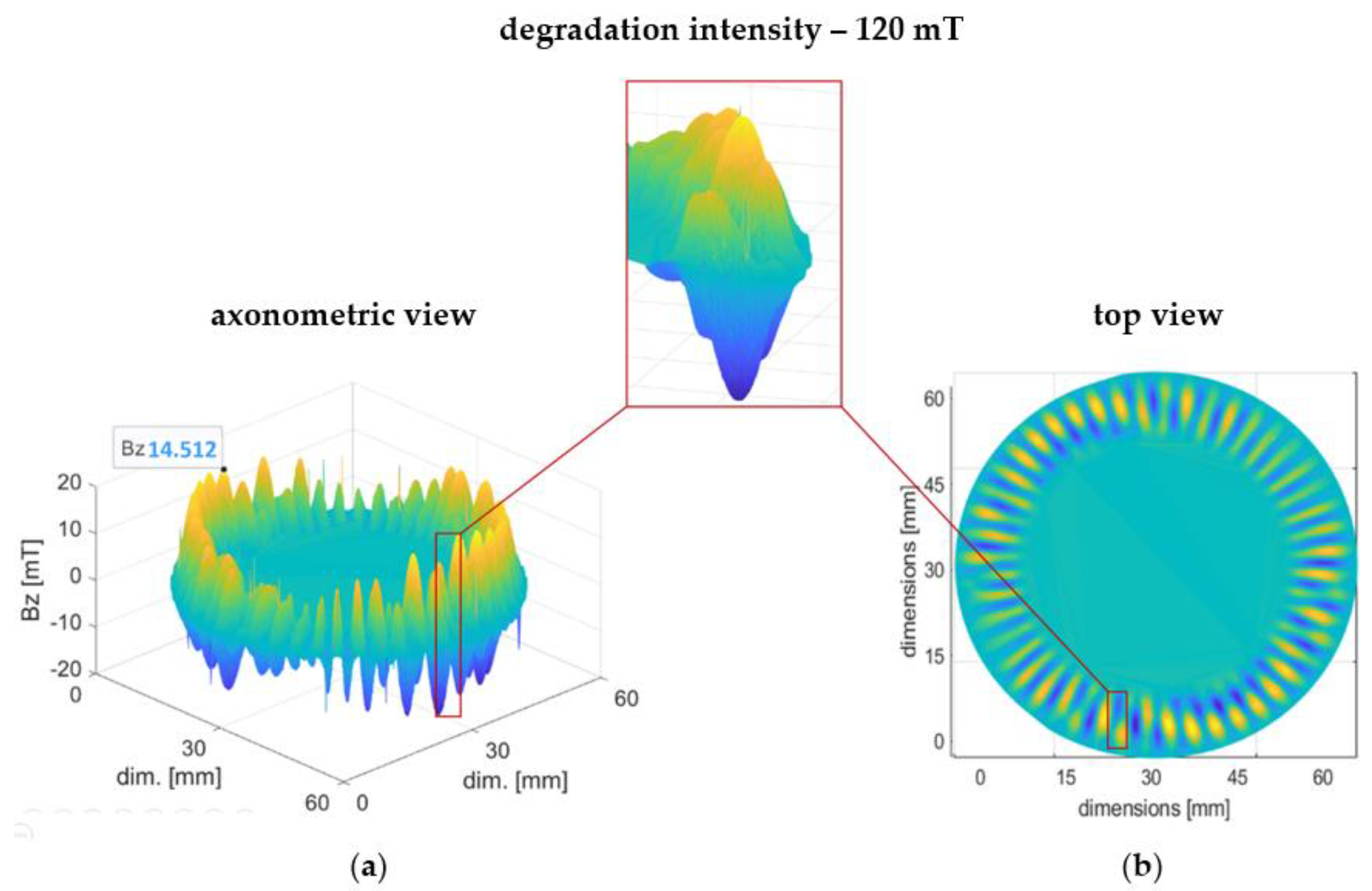
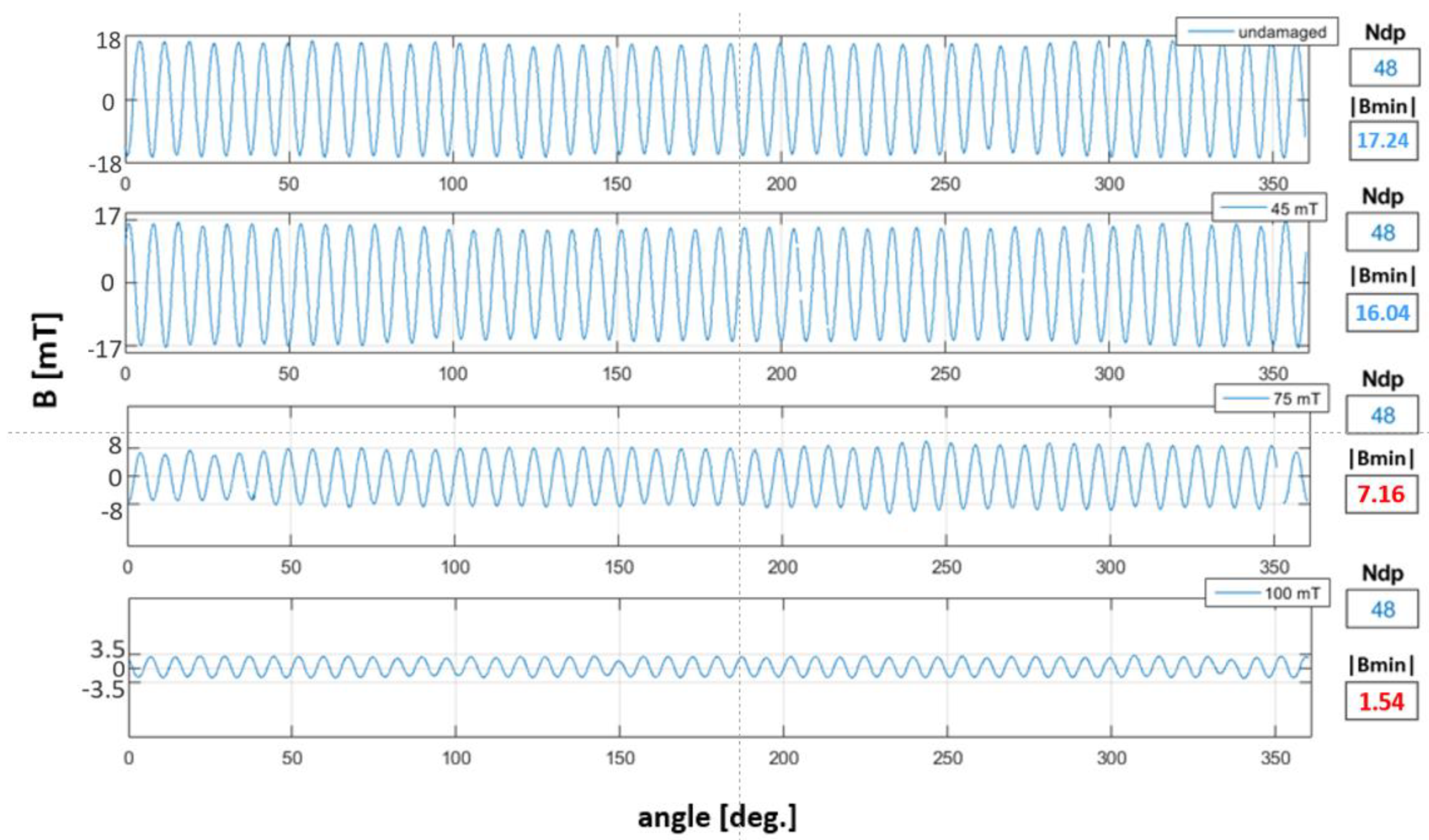
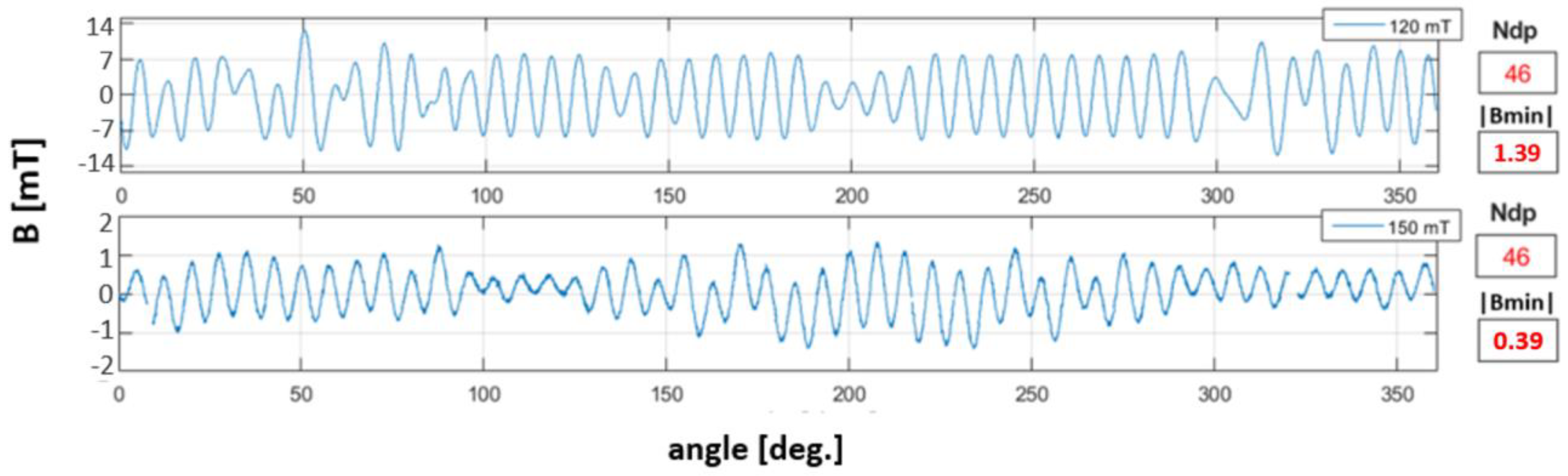
3.3. Magnetic Degradation
4. Parametric Analysis of the Results
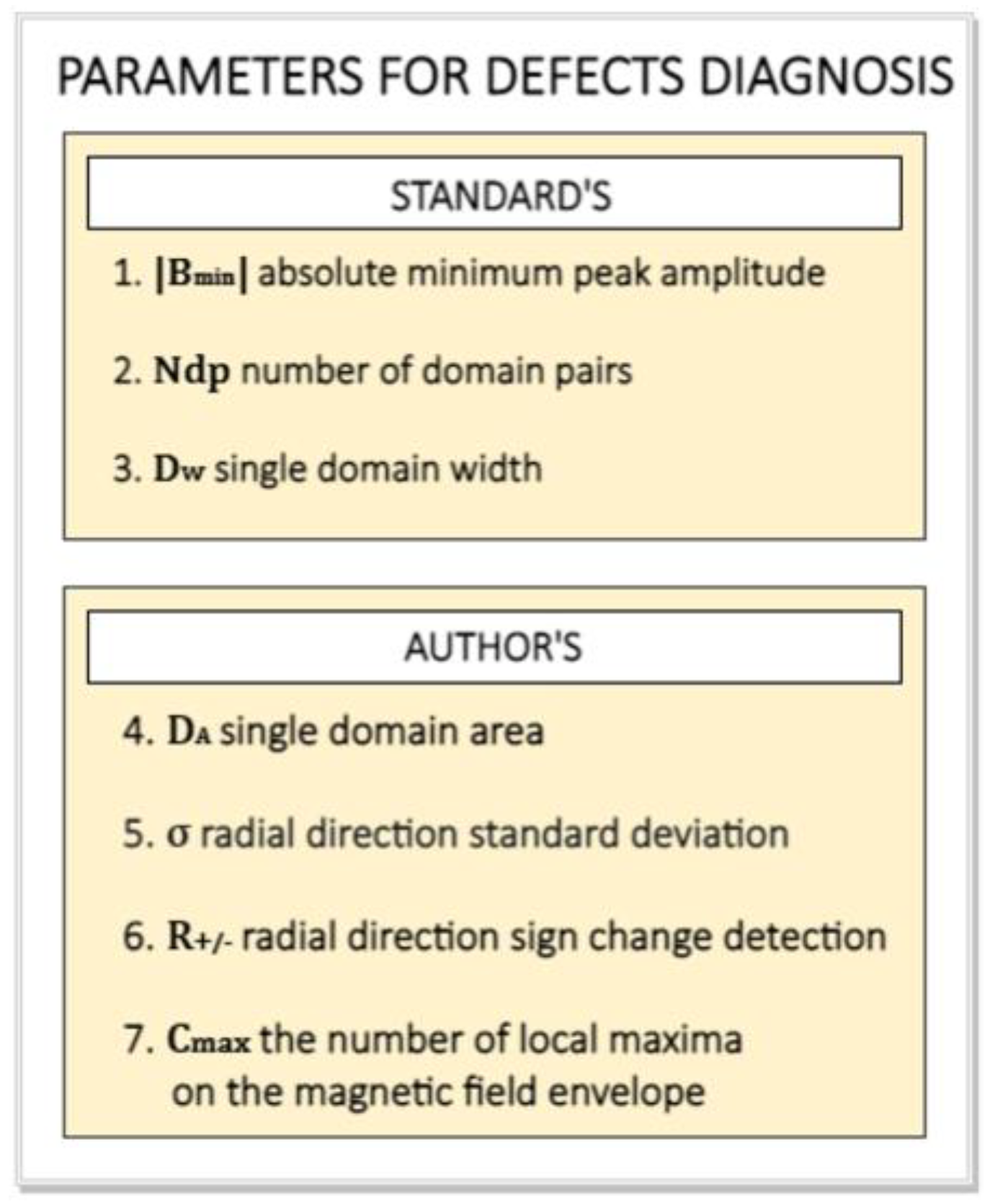
- 1.
- is the minimum absolute peak value of the magnetic induction of the encoder ring domains, Equation (3). is determined as a result of the analysis of peak values of magnetic induction of domains N and S (both positive and negative ) on the circumferential waveform of the magnetic induction signal of the encoder ring on the circumference with a given radius . should be greater than or equal to the minimum absolute value of magnetic induction specified in the standards [10,11], Equation (4).where is the measured minimum, absolute peak value of the magnetic induction value of the domains, represent the positive and negative domain peaks, and is the minimum absolute limit value of magnetic induction, specified according to the standards [10,11].
- 2.
- is the number of pairs of unlike domains, namely, N and S. The determination of the number of domain pairs is based on the number of single sine periods within the circumferential waveform of domain magnetic induction values. A single sine period denotes a set consisting of the positive domain peak and negative domain .where is the sum of sets symbol, is the positive domain peak, and is the negative domain peak.
- 3.
- is the width of a single domain, determined by the circumference with a given radius . The measure of the domain width is the number of consecutive measurement points whose induction values are the same sign: “” or “” (do not cross zero). To determine the number of positive/negative points in the magnetic induction vector , the signum function was used, Equation (6):
- 4.
- Hence, the frequencies and of the “” and “” characters, respectively, in the vector correspond to the widths of domains with positive “” and negative “” signs.
4.1. Mechanical Degradation
4.2. Thermal Degradation
4.3. Magnetic Degradation
5. Discussion
Author Contributions
Funding
Institutional Review Board Statement
Informed Consent Statement
Data Availability Statement
Conflicts of Interest
References
- Snoddy, L.B.; Beams, J.W. A Simple Method of Measuring Rotational Speeds. Science 1937, 85, 273–274. [Google Scholar] [CrossRef] [PubMed]
- MacInnes, D.A. The Use of Stroboscopic Patterns in the Determination of Speeds of Rotation. Rev. Sci. Instrum. 1943, 14, 14–16. [Google Scholar] [CrossRef]
- Robinson, C.E. Analog Tachometers. IEEE Trans. Ind. Gen. Appl. 1966, 2, 144–146. [Google Scholar] [CrossRef]
- Koerv, P.A.A. Control systems for operating the long stator Maglev vehicle TR 05. IEEE Trans. Veh. Technol. 1980, 29, 23–34. [Google Scholar] [CrossRef]
- Çakar, H.; Khelf, I.; Andre, H. Investigation of the Influence of the Operating Parameters on the Magnetic Encoder Geometric Error Compensation. In Proceedings of the Surveillance, Vishno and AVE conferences, INSA-Lyon, Université de Lyon, Lyon, France, 8–10 July 2019. [Google Scholar]
- Draxelmayr, D.; Borgschulze, R. A self-calibrating Hall sensor IC with direction detection. IEEE J. Solid-State Circuits 2003, 38, 1207–1212. [Google Scholar] [CrossRef]
- Bosch, R. (Ed.) Bosch Automotive Electrics and Automotive Electronics: Systems and Components, Networking and Hybrid Drive; Springer Fachmedien Wiesbaden: Wiesbaden, Germany, 2014; ISBN 978-3-658-01783-5. [Google Scholar]
- Alcázar Vargas, M.; Pérez Fernández, J.; Velasco García, J.M.; Cabrera Carrillo, J.A.; Castillo Aguilar, J.J. A Novel Method for Determining Angular Speed and Acceleration Using Sin-Cos Encoders. Sensors 2021, 21, 577. [Google Scholar] [CrossRef] [PubMed]
- Magnet Ring for Industrial Applications. Available online: https://www.hutchinson.com/en/products/magnetic-ring-industrial-applications (accessed on 8 April 2023).
- FCA Cluster Norm, no. FCA Cluster Norm, no. 9.92650; FCA Company: London, UK, 2014. [Google Scholar]
- PSA Magnetic Encoder, Technical Specification; PSA Peugeot Citroen: Paris, France, 2011.
- Volkswagen Aktiengesellschaft, ‘Volkswagen Konzernnorm TL 82396’. 2011. Available online: https://www.volkswagenag.com/ (accessed on 8 April 2023).
- Jebelli, A.; Mahabadi, A.; Yagoub, M.C.E.; Chaoui, H. Magnetic Force Calculation between Magnets and Coils. Int. J. Phys. 2020, 8, 71–80. [Google Scholar] [CrossRef]
- Gontarz, S.; Szulim, P. Evaluation of the impact of environmental hazards associated with mechanical faults in BLDC electric motors. Environ. Eng. Manag. J. 2016, 15, 491–504. [Google Scholar] [CrossRef]
- Datasheet for MLX90395, Melexis. Available online: https://www.melexis.com/en/documents/documentation/datasheets/datasheet-mlx90395 (accessed on 8 April 2023).
- Kittel, C. Introduction to Solid State Physics, 8th ed.; Wiley: Hoboken, NJ, USA, 2005; ISBN 978-0-471-41526-8. [Google Scholar]
- Lovric, M. (Ed.) Standard Deviation. In International Encyclopedia of Statistical Science; Springer: Berlin/Heidelberg, Germany, 2011; pp. 1378–1379. ISBN 978-3-642-04898-2. [Google Scholar]
- Cox, B.; Van der Perre, L.; Wielandt, S.; Ottoy, G.; De Strycker, L. High precision hybrid RF and ultrasonic chirp-based ranging for low-power IoT nodes. EURASIP J. Wirel. Commun. Netw. 2020, 2020, 187. [Google Scholar] [CrossRef]


| Type of Degradation | ||||
|---|---|---|---|---|
| No. | A. Mechanical Abrasion [mm] * | B. Magnetic Field [mT] ** | C. Temperature [K] | |
| INTENSITY | 1. | 0.00 | 0 | 293 *** |
| 2. | 0.23 | 45 | 603 | |
| 3. | 0.25 | 75 | 653 | |
| 4. | 0.30 (+ cavities) | 100 | 713 | |
| 5. | 0.35 | 120 | 753 | |
| 6. | 0.50 | 50 | 783 | |
| Parameter | |
| A. Magnetic Field | B. Machnical Abrasion | C. Heat | |||||
|---|---|---|---|---|---|---|---|
| I Stage | II Stage | Regular | +Cavities | I Stage | II Stage | ||
| PARAMETERS | 1. |  | | | | ✓ | |
| 2. | ✓ | | ✓ | ✓ | ✓ | | |
| 3. | ✓ | | ✓ | ✓ | ✓ | | |
| 4. | ✓ | | ✓ | ✓ | ✓ | | |
| 5. | ✓ | – | | – | ✓ | – | |
| 6. | ✓ | | ✓ | ✓ | ✓ | ✓ | |
| 7. | – | – | ✓ | | – | – | |
wrong; — not applicable.Disclaimer/Publisher’s Note: The statements, opinions and data contained in all publications are solely those of the individual author(s) and contributor(s) and not of MDPI and/or the editor(s). MDPI and/or the editor(s) disclaim responsibility for any injury to people or property resulting from any ideas, methods, instructions or products referred to in the content. |
© 2023 by the authors. Licensee MDPI, Basel, Switzerland. This article is an open access article distributed under the terms and conditions of the Creative Commons Attribution (CC BY) license (https://creativecommons.org/licenses/by/4.0/).
Share and Cite
Popowska, K.; Gontarz, S.; Szulim, P. Identification of the Domain Structure Defects of a Radially Magnetized Rubber–Ferritic Conglomerate. Materials 2023, 16, 3487. https://doi.org/10.3390/ma16093487
Popowska K, Gontarz S, Szulim P. Identification of the Domain Structure Defects of a Radially Magnetized Rubber–Ferritic Conglomerate. Materials. 2023; 16(9):3487. https://doi.org/10.3390/ma16093487
Chicago/Turabian StylePopowska, Karolina, Szymon Gontarz, and Przemysław Szulim. 2023. "Identification of the Domain Structure Defects of a Radially Magnetized Rubber–Ferritic Conglomerate" Materials 16, no. 9: 3487. https://doi.org/10.3390/ma16093487
APA StylePopowska, K., Gontarz, S., & Szulim, P. (2023). Identification of the Domain Structure Defects of a Radially Magnetized Rubber–Ferritic Conglomerate. Materials, 16(9), 3487. https://doi.org/10.3390/ma16093487