
3D Printed (Binder Jetting) Furan Molding and Core Sands—Thermal Deformation, Mechanical and Technological Properties
 , , , and
Abstract
1. Introduction
- Durability and time-regulated shelf life for molding;
- High resistance-to-moisture during core storage;
- High resistance-to-erosion and -penetration and no chemical interaction with the casting alloy;
- High gas permeability;
- High strength;
- Easy knockout properties;
- Good susceptibility to regeneration of used molding sand;
- Lower capital expenditure;
- No need to heat core boxes;
- High surface quality of castings;
- Environmentally friendly core systems with low odor.
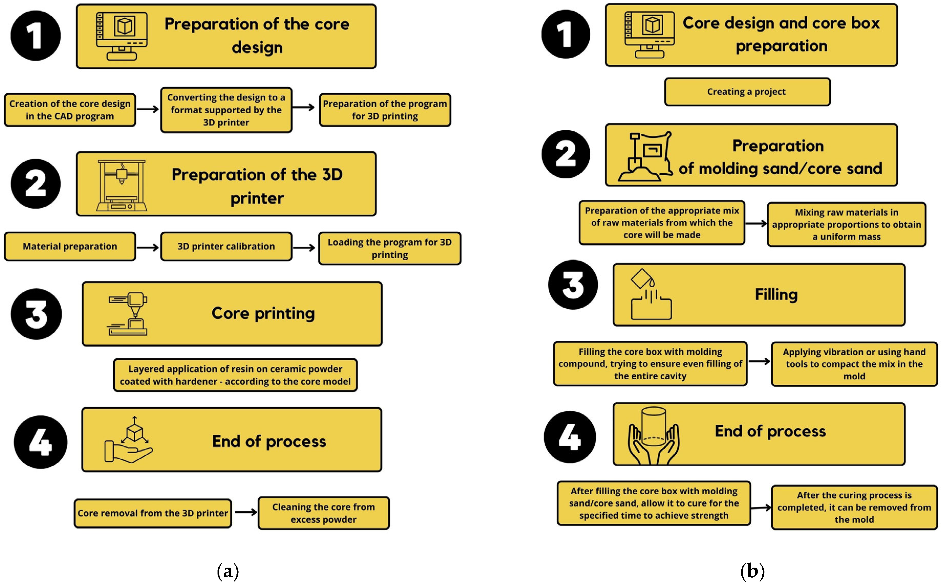
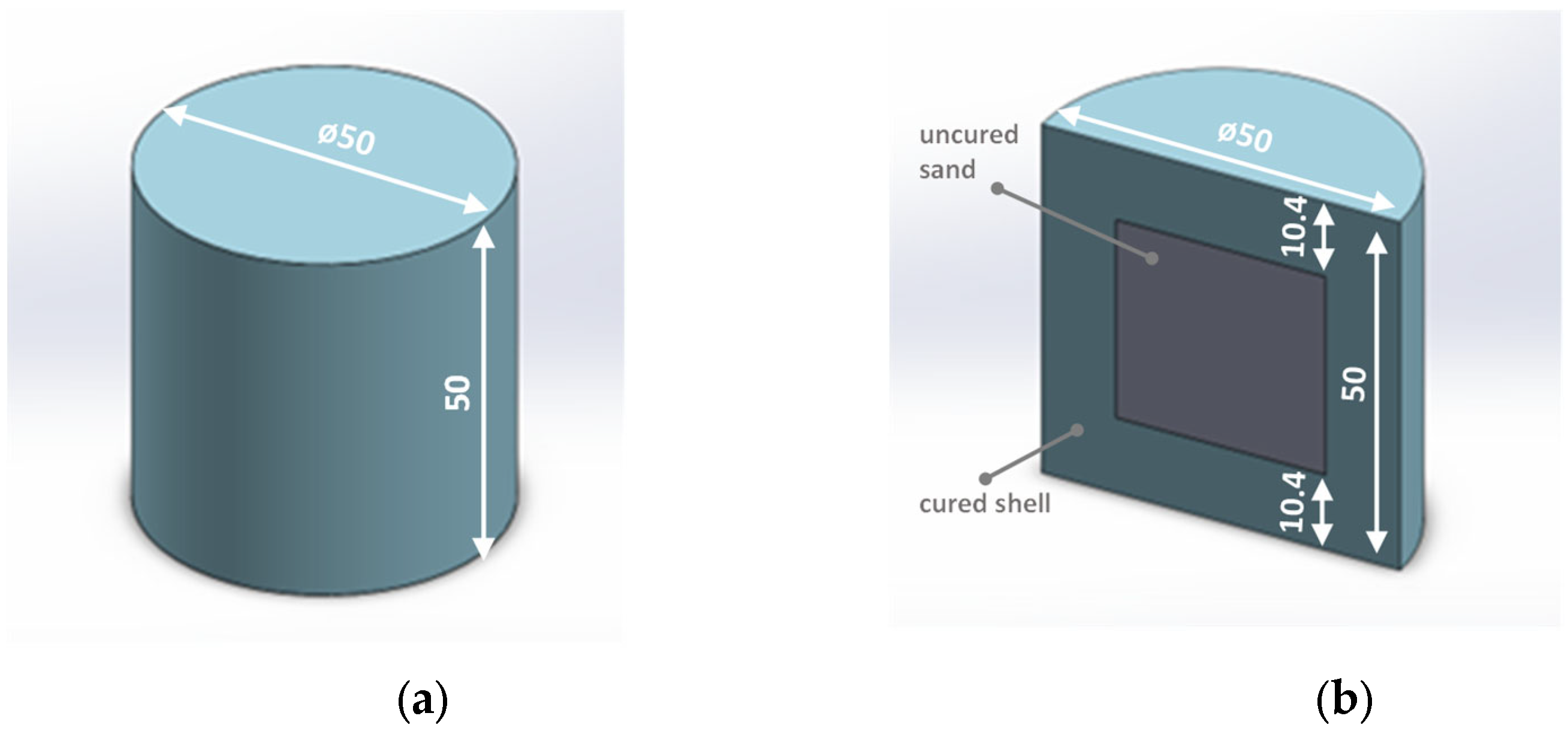
- Determination of the mechanical and technological properties of the shell core made in additive manufacturing (Figure 1a) and comparing them with the properties of cores made with conventional technology (mixing and compaction) (Figure 1b), taking into account the size of the quartz sand grain (friability and permeability). This research aimed at identifying the possibility of reducing the consumption of resin during 3D printing in order to improve the economics of the process and reduce the formation of defects in castings of gas origin, which are closely related to the amount of organic additives introduced into the molding (core) sands.
- Comparison of thermal deformation of cores made by using a binder dedicated to 3D printing, with cores made by using the typical FNB system (furan no-bake system).
- Determining the possibility of an interchangeable use of a binder dedicated to 3D printing in typical FNB technology.
- Determination of binding (hardening) kinetics expressed by core strength over time, depending on the size of the grain matrix and the share of the binder in the molding (core) sand.
- Properties of molding sands prepared with the use of two binders (conventional and dedicated to 3D printing), on the specific matrix graining (e.g., sieved fraction), using a composition dedicated to 3D printing, i.e., 1.5 parts by weight of resin and 0.4 parts by weight of hardener.
- The influence of the amount of binder on the properties of core sands, with a conventional binder as a reference point.
2. Materials and Methods
2.1. Materials
2.2. Mechanical and Technological Properties of Cores (Standard Specimens—Cylindrical Shape) Made by 3D Printing Technology
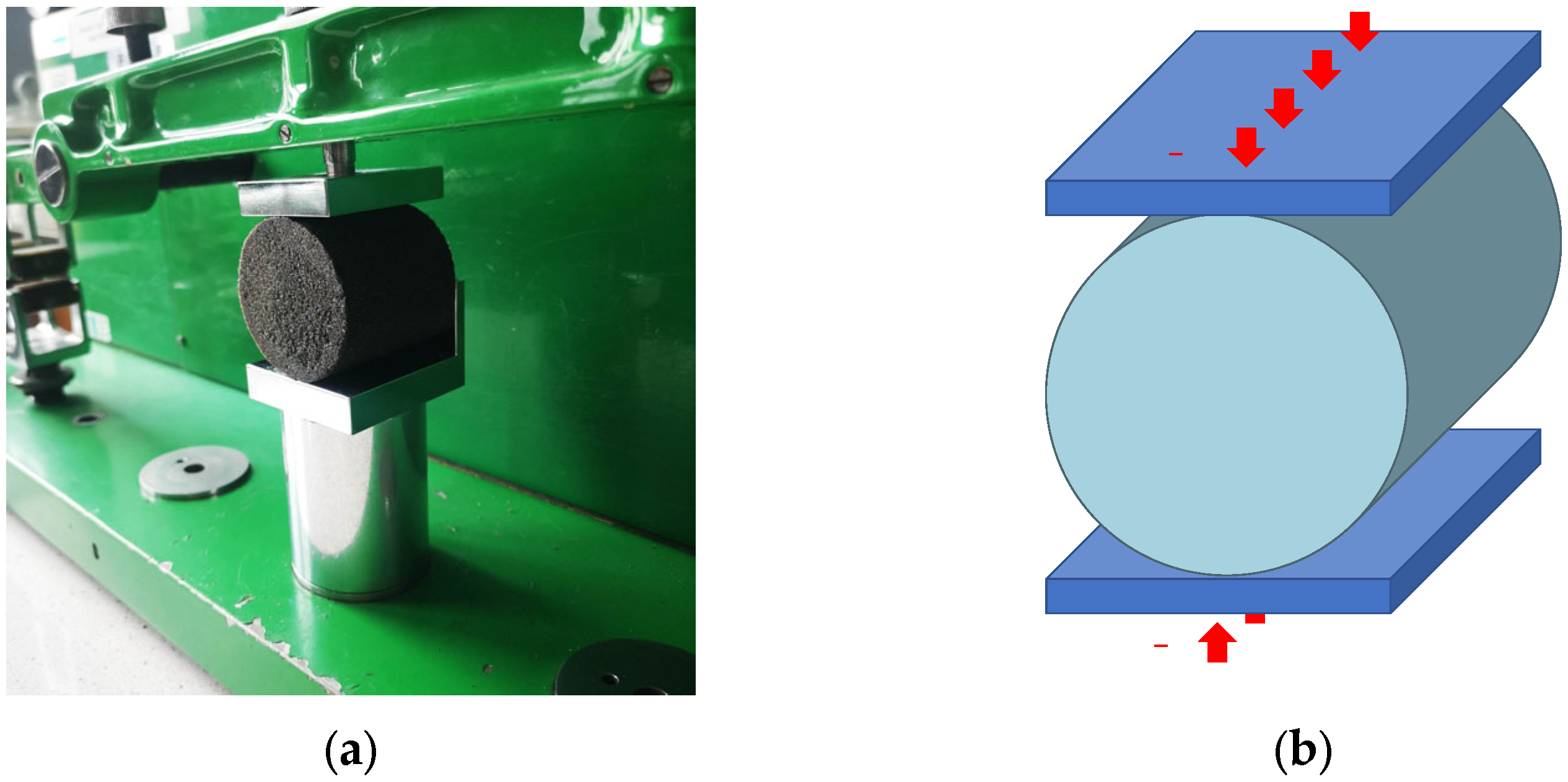
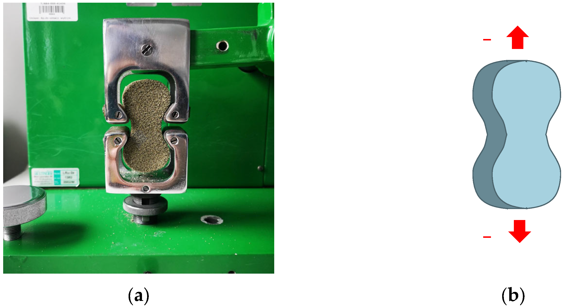
- Splitting tensile strength () using the LRu-2e universal tester of mechanical properties of molding sand (Multiserw-Morek, Marcyporęba, Poland) [38]; in this test, the specimen is placed horizontally between the rigid loading plates of the compression apparatus (Figure 3a). Then, the load is vertically applied and increased along the two peaks of the specimen’s diameter, top and bottom, until the specimen’s destruction (Figure 3b);
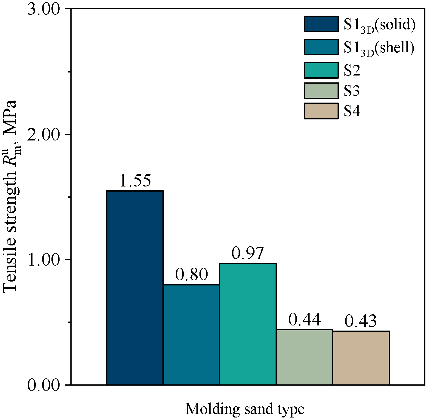
- Tensile strength molding sands in a hardened state ( were calculated according to the correlation given in [39], i.e., = 0.65;
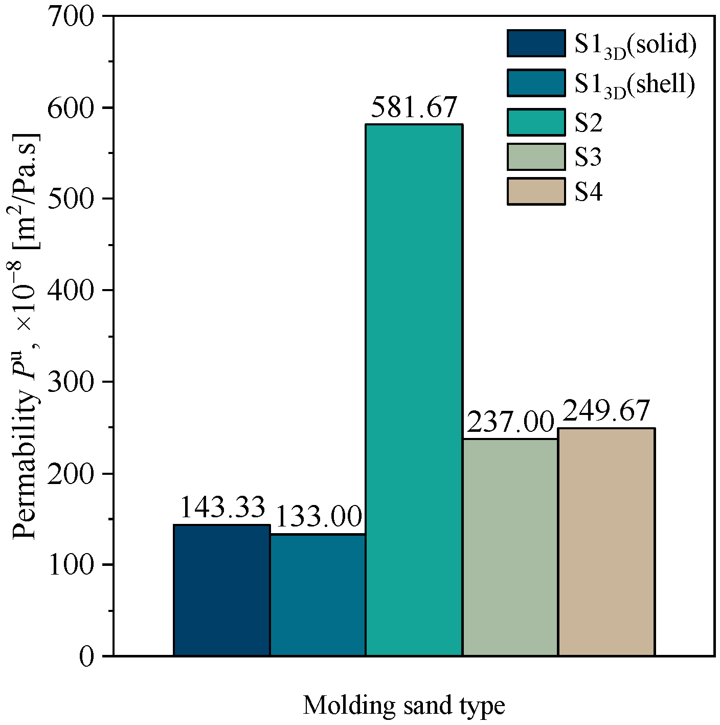
- Permeability (Pu) was performed by the fast method on electrical apparatus type LpiR-3e [40];
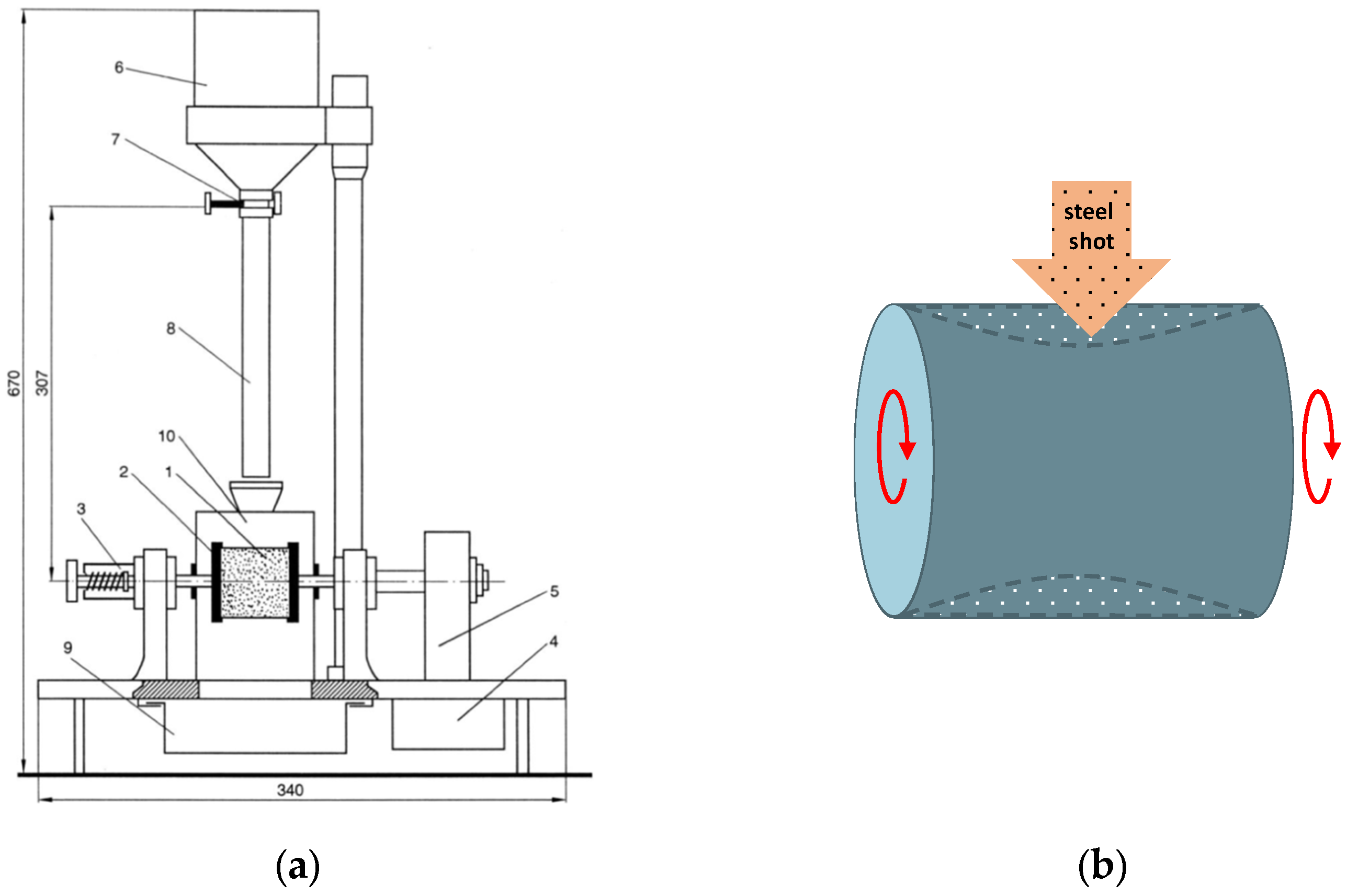
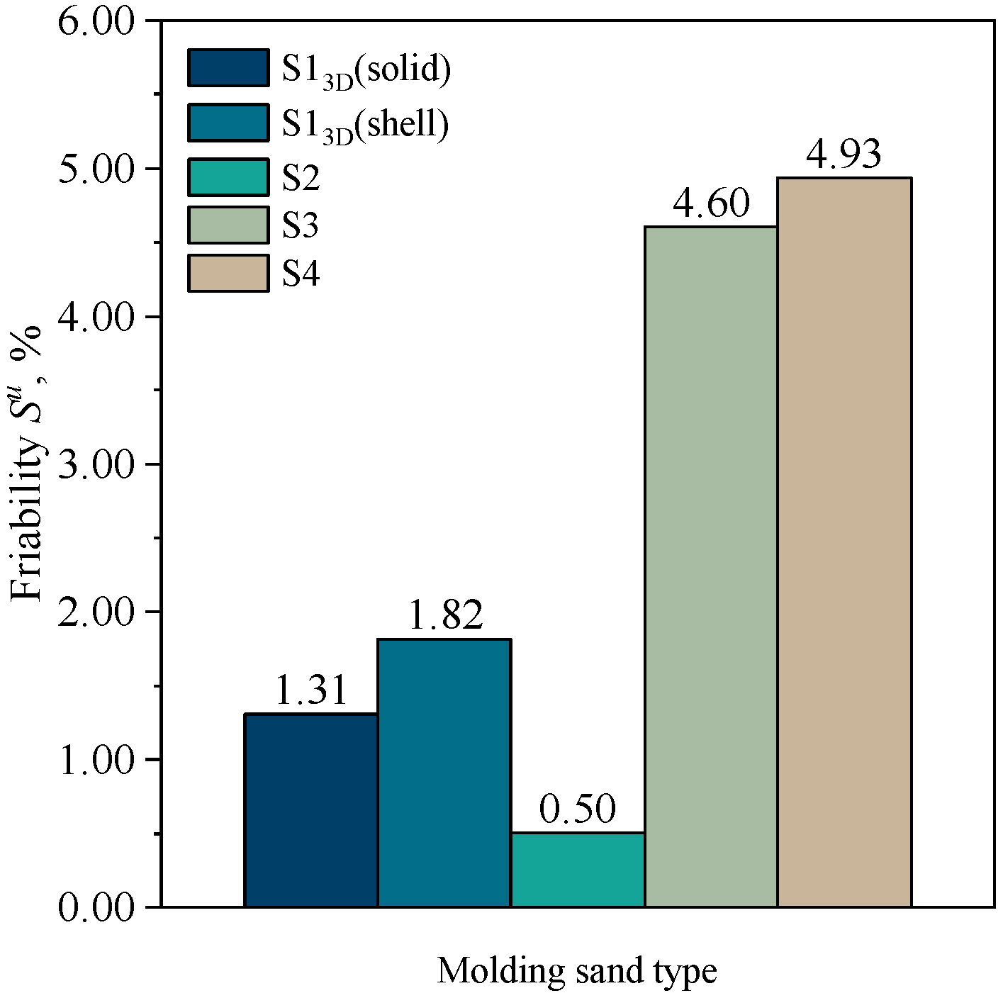
- Friability (Su) was performed by using the HSW apparatus (Huta Stalowa Wola, Stalowa Wola, Poland). Figure 4a shows a scheme of the apparatus for determining the friability of hardened molding sand. The principle of this apparatus is as follows: A standardized cylindrical specimen (1), made of a hardened molding sand, is seated in a holder (2) by using a clamp (3). The clamped specimen is put into rotary motion at a speed of 1 rpm/s by an electric motor (4) via a gearbox (5). The electric motor is powered directly from the 220 V mains. At the top of the apparatus is placed a steel shot container (6) with a funnel-shaped bottom ending in a hole (Ø7 mm), closed by a slide bolt (7). The shot from the container falls during the marking with a tube (8) (from a height of 307 mm) on the rotating shaper and causes its abrasion (Figure 4b). The separated mass together with the shot falls into the tank (9). During the measurement, the specimen is enclosed in a shield (10), which prevents the shot and molding sand from spreading sideways.
- Q1—weight of the specimen before testing [g];
- Q2—weight of the specimen after testing [g].
2.3. Investigations of Mechanical and Technological Properties of Cores (Standard Samples)
2.4. Tensile Strength as a Function of Hardening Time
2.5. Thermal Deformation (Hot-Distortion) Tests
3. Results
3.1. Loss of Ignition
3.2. Sieve Analysis
3.3. Mechanical Properties
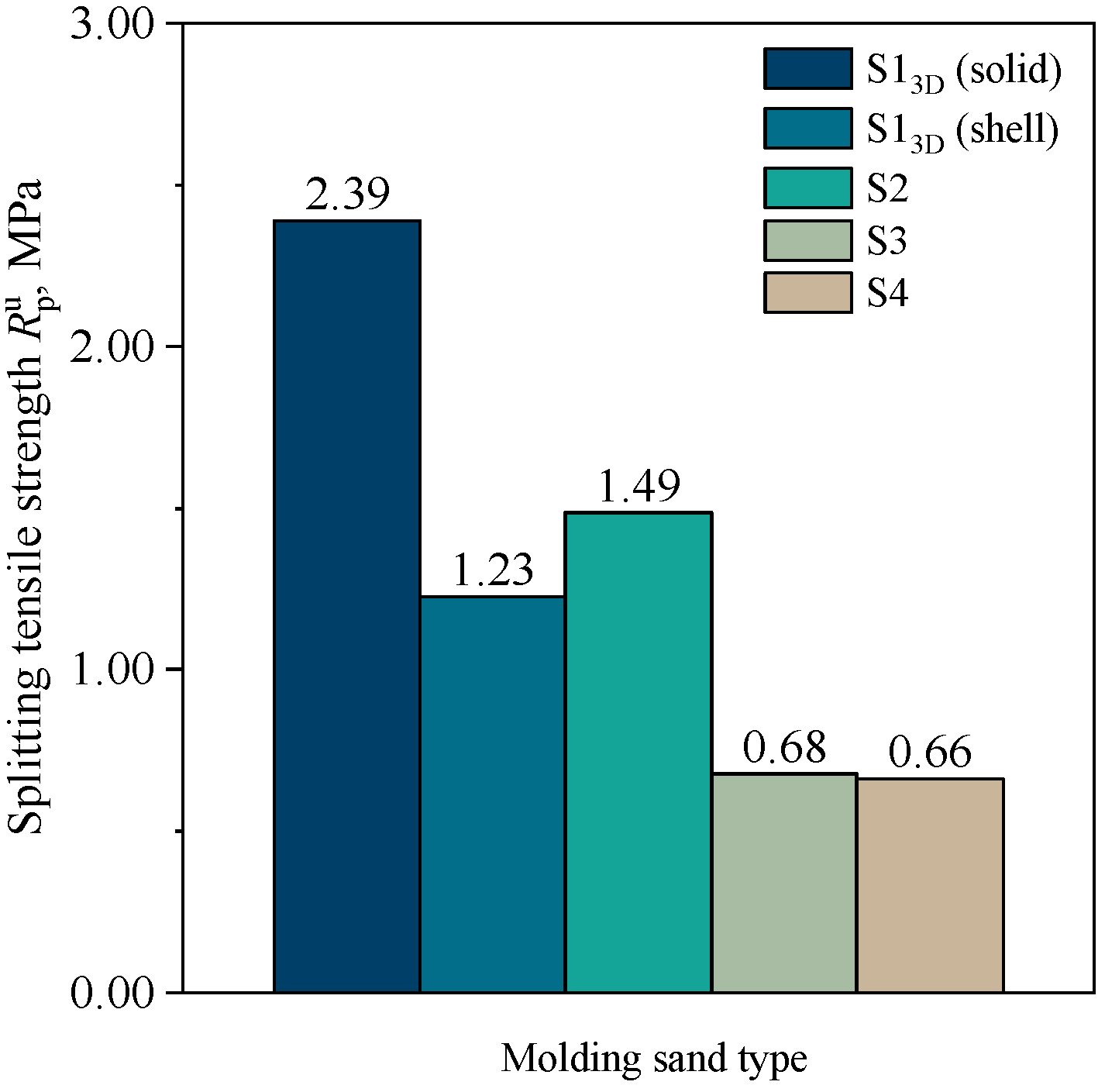
3.3.1. Splitting Tensile Strength
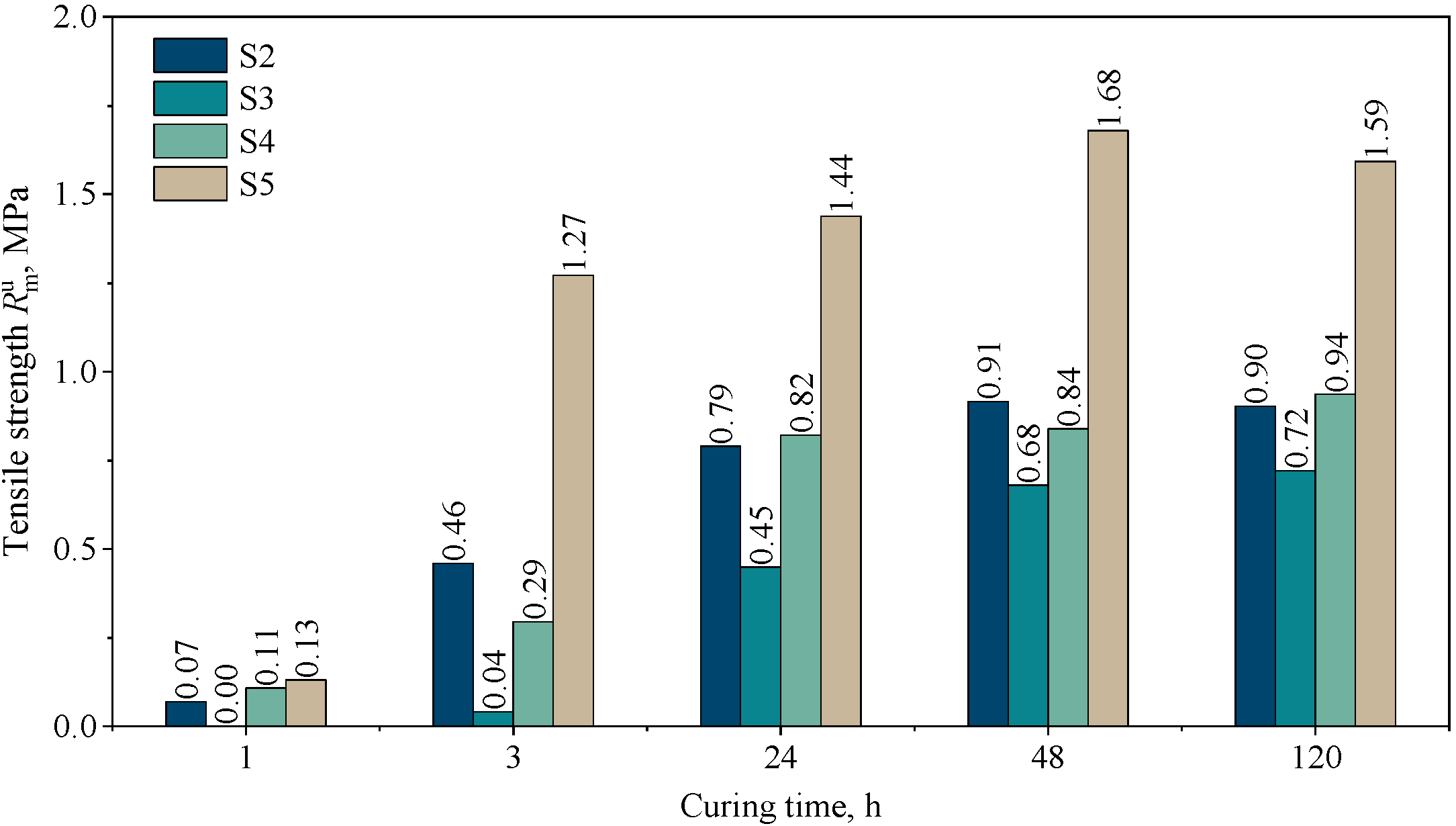
3.3.2. Tensile Strength as a Function of Curing Time
3.4. Technological Properties
Permeability
3.5. Friability
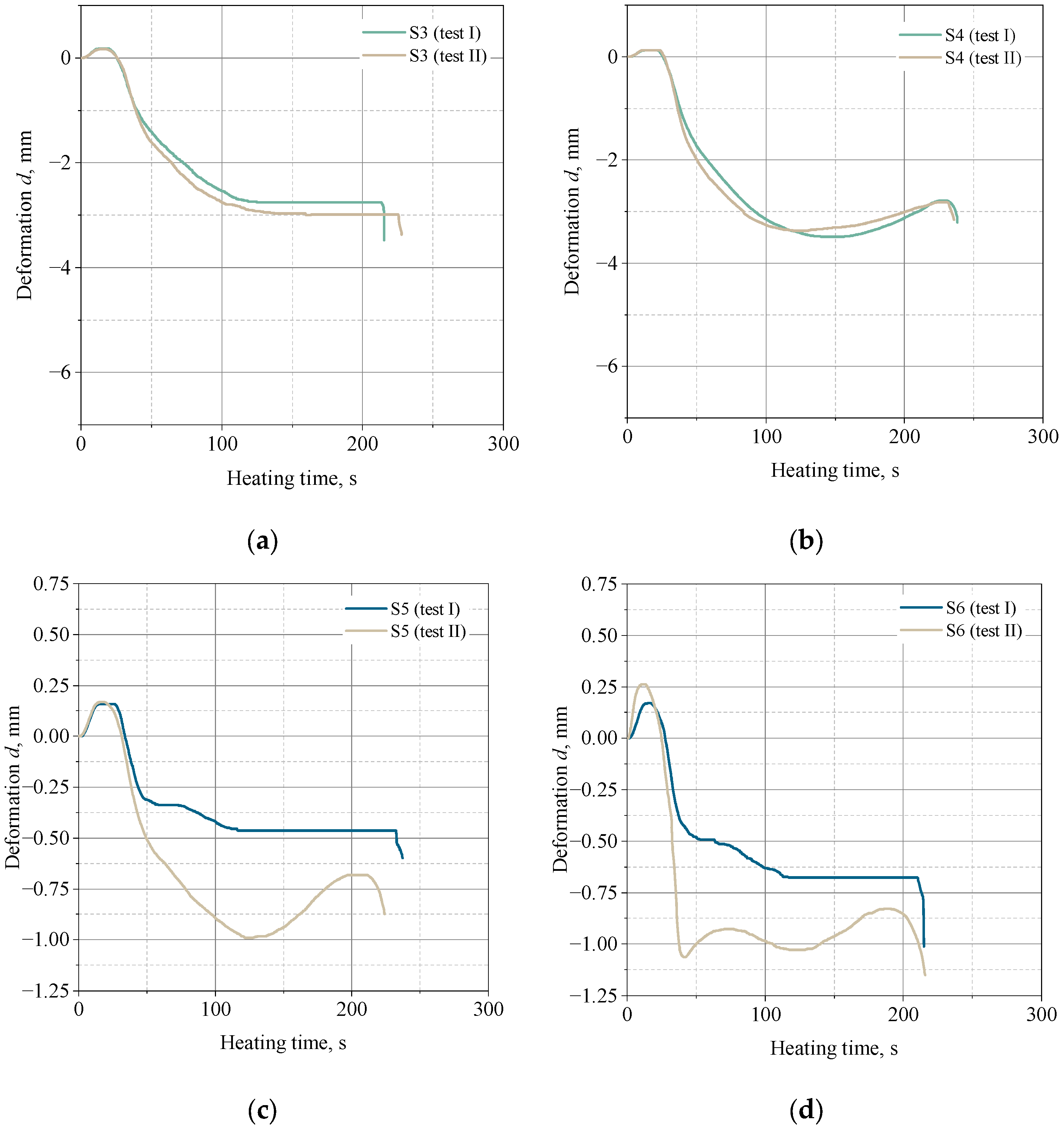
3.6. Hot-Distortion
4. Conclusions
- The highest mechanical strength is achieved by cores made by using 3D printing technology;
- Shell (3D-printed) cores are characterized by lower mechanical strength but are similar to cores made with conventional technology. Considering the high cost of purchasing sand, resin, and hardener, one can consider switching to such a production system, taking into account the proper thickness of the core wall;
- The use of a binder dedicated to 3D printing in conventional technology (mixing and compacting) is not justified both from a technological and economic point of view;
- Printed cores (solid and shell) have similar a permeability, but are the lowest of all the tested systems;
- The friability of 3D-printed cores is at a low level, due to their high mechanical properties;
- Three-dimensionally printed cores show a negligible susceptibility to thermal deformation and a resistance to high temperature;
- The most significant influence on the thermal deformation of molding sands is the binder content. It has been noted that molding sands with a binder dedicated to 3D printing (FB001 and FA001) show greater susceptibility to deformation compared to typical binders (Kaltharz U404 + 100T3);
- By reducing the amount of binder by 0.5 parts by weight, the deformation of the sample is reduceable by up to two times.
Author Contributions
Funding
Institutional Review Board Statement
Informed Consent Statement
Data Availability Statement
Conflicts of Interest
References
- Mitra, S.; Rodríguez de Castro, A.; El Mansori, M. The Effect of Ageing Process on Three-Point Bending Strength and Permeability of 3D Printed Sand Molds. Int. J. Adv. Manuf. Technol. 2018, 97, 1241–1251. [Google Scholar] [CrossRef]
- Czerwinski, F.; Mir, M.; Kasprzak, W. Application of Cores and Binders in Metalcasting. Int. J. Cast Met. Res. 2015, 28, 129–139. [Google Scholar] [CrossRef]
- Kubecki, M.; Holtzer, M.; Bobrowski, A.; Dańko, R.; Grabowska, B.; Żymankowska-Kumon, S. Group, Emitted During Thermal Decomposition of Alkyd Resin. Arch. Foundry Eng. 2012, 12, 69–74. [Google Scholar] [CrossRef]
- Bobrowski, A.; Holtzer, M.; Zymankowska-Kumon, S.; Dańko, R. Harmfulness Assessment of Moulding Sands with a Geopolymer Binder and a New Hardener, in an Aspect of the Emission of Substances from the BTEX Group. Arch. Metall. Mater. 2015, 60, 341–344. [Google Scholar] [CrossRef]
- Zymankowska-Kumon, S.; Bobrowski, A.; Grabowska, B. Comparison of the Emission of Aromatic Hydrocarbons from Moulding Sands with Furfural Resin with the Low Content of Furfuryl Alcohol and Different Activators. Arch. Foundry Eng. 2016, 16, 187–190. [Google Scholar] [CrossRef]
- Bobrowski, A.; Zymankowska-Kumon, S.; Drozyński, D.; Grabowska, B.; Kaczmarska, K. TG/DTG/DTA, FTIR and GC/MS Studies of Oil Sand for Artistic and Precision Foundry with the Emission of Gases Assessment. Arch. Foundry Eng. 2017, 17, 25–30. [Google Scholar] [CrossRef]
- Bobrowski, A.; Kmita, A.; Starowicz, M.; Stypuła, B.; Hutera, B. Effect of Magnesium Oxide Nanoparticles on Water Glass Structure. Arch. Foundry Eng. 2012, 12, 9–12. [Google Scholar] [CrossRef]
- Puzio, S.; Kamińska, J.; Major-Gabryś, K.; Angrecki, M.; Hosadyna-Kondracka, M. Microwave-Hardened Moulding Sands with Hydrated Sodium Silicate for Modified Ablation Casting. Arch. Foundry Eng. 2019, 19, 91–96. [Google Scholar] [CrossRef]
- Stachowicz, M.; Granat, K.; Pałyga, Ł. The Effect of Wetting Agent on the Parameters of Dry Moulding Silica Sands Bonded with Sodium Water Glass. Trans. Foundry Res. Inst. 2016, 56, 43–55. [Google Scholar]
- Kamińska, J.; Angrecki, M.; Palma, A.; Jakubski, J.; Wildhirt, E. The Effect of Additive “b” on the Properties of CO2-Hardened Foundry Sands with Hydrated Sodium Silicate. Arch. Metall. Mater. 2017, 62, 1637–1641. [Google Scholar] [CrossRef]
- Major-Gabryś, K.; Puzio, S.; Bryłka, A.; Kamińska, J. The Influence of Various Matrixes on the Strength Properties of Moulding Sands with Thermally Hardened Hydrated Sodium Silicate for the Ablation Casting Process. J. Cast. Mater. Eng. 2021, 5, 31–35. [Google Scholar] [CrossRef]
- Lee, W.-H.; Wu, Y.-F.; Ding, Y.-C.; Cheng, T.-W. Fabrication of Ceramic Moulds Using Recycled Shell Powder and Sand with Geopolymer Technology in Investment Casting. Appl. Sci. 2020, 10, 4577. [Google Scholar] [CrossRef]
- Bobrowski, A.; Kaczmarska, K.; Sitarz, M.; Drożyński, D.; Leśniak, M.; Grabowska, B.; Nowak, D. Dehydroxylation of Perlite and Vermiculite: Impact on Improving the Knock-Out Properties of Moulding and Core Sand with an Inorganic Binder. Materials 2021, 14, 2946. [Google Scholar] [CrossRef]
- Major-Gabryś, K.; Dobosz, S.M. High-Temperature Expansion and Knock-out Properties of Moulding Sands with Water Glass—Archives of Foundry Engineering—Tom Vol. 7, Iss. 1 (2007)—BazTech—Yadda. Arch. Foundry Eng. 2007, 7, 127–130. [Google Scholar]
- Budavári, I.; Varga, L. The Effect of Coremaking Parameters on the Thermal Distortion Behaviour of Resin-Coated Sand. Mater. Sci. Eng. 2022, 45, 37–49. [Google Scholar]
- Tshabalala, N.V.; Nyembwe, K.D.; van Tonder, P.J.M. Optimisation of a Resin-Coated Chromite Sand for Rapid Sand Casting Applications. S. Afr. J. Ind. Eng. 2021, 32, 290–298. [Google Scholar] [CrossRef]
- Wan, P.; Li, L.C.; Zhang, L.; Wang, W.Q. Research on Testing Method of Resin Sand High Temperature Compressive Strength. China Foundry 2016, 13, 335–341. [Google Scholar] [CrossRef]
- Khandelwal, H.; Ravi, B. Effect of Molding Parameters on Chemically Bonded Sand Mold Properties. J. Manuf. Process. 2016, 22, 127–133. [Google Scholar] [CrossRef]
- Sucarz, M.; Dańko, R.; Dereń, M.; Skrzyński, M. Investigation of the Results of Combined Reclamation on the Particular Stages of Grain Matrix Recovery. Arch. Metall. Mater. 2016, 61, 2151–2158. [Google Scholar] [CrossRef]
- Dańko, R. Criteria for an Advanced Assessment of Quality of Moulding Sands with Organic Binders and Reclamation Process Products. China Foundry 2013, 10, 181–186. [Google Scholar]
- Bargaoui, H.; Azzouz, F.; Thibault, D.; Cailletaud, G. Thermomechanical Behavior of Resin Bonded Foundry Sand Cores during Casting. J. Mater. Process. Technol. 2017, 246, 30–41. [Google Scholar] [CrossRef]
- Huang, R.; Gao, H.; Tang, Y. Curing Mechanism of Furan Resin Modified with Different Agents and Their Thermal Strength. China Foundry 2012, 8, 161–165. [Google Scholar]
- Upadhyay, M.; Sivarupan, T.; El Mansori, M. 3D Printing for Rapid Sand Casting—A Review. J. Manuf. Process. 2017, 29, 211–220. [Google Scholar] [CrossRef]
- Hackney, P.M.; Wooldridge, R. 3D Sand Printing for Automotive Mass Production Applications. Int. J. Rapid Manuf. 2017, 6, 134. [Google Scholar] [CrossRef]
- Sivarupan, T.; Balasubramani, N.; Saxena, P.; Nagarajan, D.; El Mansori, M.; Salonitis, K.; Jolly, M.; Dargusch, M.S. A Review on the Progress and Challenges of Binder Jet 3D Printing of Sand Moulds for Advanced Casting. Addit. Manuf. 2021, 40, 101889. [Google Scholar] [CrossRef]
- Gawronová, M.; Lichý, P.; Kroupová, I.; Obzina, T.; Beňo, J.; Nguyenová, I.; Merta, V.; Jezierski, J.; Radkovský, F. Evaluation of Additive Manufacturing of Sand Cores in Terms of the Resulting Surface Roughness. Heliyon 2022, 8, e10751. [Google Scholar] [CrossRef]
- Snelling, D.A.; Williams, C.B.; Druschitz, A.P. Mechanical and Material Properties of Castings Produced via 3D Printed Molds. Addit. Manuf. 2019, 27, 199–207. [Google Scholar] [CrossRef]
- Voney, V.; Odaglia, P.; Brumaud, C.; Dillenburger, B.; Habert, G. From Casting to 3D Printing Geopolymers: A Proof of Concept. Cem. Concr. Res. 2021, 143, 106374. [Google Scholar] [CrossRef]
- Heath, A.; Paine, K.; McManus, M. Minimising the Global Warming Potential of Clay Based Geopolymers. J. Clean. Prod. 2014, 78, 75–83. [Google Scholar] [CrossRef]
- Voney, V.; Odaglia, P.; Brumaud, C.; Dillenburger, B.; Habert, G. Geopolymer Formulation for Binder Jet 3D Printing. In RILEM Bookseries; Springer: Berlin/Heidelberg, Germany, 2020; Volume 28, pp. 153–161. [Google Scholar]
- ExOne. Binder Jetting Technology. Available online: https://www.exone.com/en-US/resources/case-studies/what-is-binder-jetting (accessed on 13 March 2023).
- Yang, W.; Yan, Y.; Zhang, R.; Liu, L. Effective Factors on Forming Precision in Patternless Casting Manufacturing Technique. Tsinghua Sci. Technol. 2009, 14, 180–185. [Google Scholar] [CrossRef]
- Hackney, P.; Wooldridge, R. Optimisation of Additive Manufactured Sand Printed Mould Material for Aluminium Castings. Procedia Manuf. 2017, 11, 457–465. [Google Scholar] [CrossRef]
- Sivarupan, T.; El Mansori, M.; Coniglio, N.; Dargusch, M. Effect of Process Parameters on Flexure Strength and Gas Permeability of 3D Printed Sand Molds. J. Manuf. Process. 2020, 54, 420–437. [Google Scholar] [CrossRef]
- Snelling, D.; Williams, C.; Druschitz, A. A Comparison of Binder Burnout and Mechanical Characteristics of Printed and Chemically Bonded Sand Molds. In Proceedings of the 2014 International Solid Freeform Fabrication Symposium, Austin, TX, USA, 4–6 August 2014; pp. 197–209. [Google Scholar]
- Shangguan, H.; Kang, J.; Deng, C.; Hu, Y.; Huang, T. 3D-Printed Shell-Truss Sand Mold for Aluminum Castings. J. Mater. Process. Technol. 2017, 250, 247–253. [Google Scholar] [CrossRef]
- Coniglio, N.; Sivarupan, T.; El Mansori, M. Investigation of Process Parameter Effect on Anisotropic Properties of 3D Printed Sand Molds. Int. J. Adv. Manuf. Technol. 2018, 94, 2175–2185. [Google Scholar] [CrossRef]
- Urządzenie Do Badania Wytrzymałości Mas Formierskich—Multiserw-Morek. Available online: http://multiserw-morek.pl/products,urzadzenia_do_badania_mas_formierskich_i_rdzeniowych,urzadzenie_do_badania_wytrzymalosci_mas_formierskich (accessed on 22 March 2023).
- Lewandowski, J.L. Tworzywa Na Formy Odlewnicze; Akapit: Kraków, Poland, 1997. [Google Scholar]
- Urządzenie Do Pomiaru Przepuszczalności Mas Formierskich—Multiserw-Morek. Available online: http://multiserw-morek.pl/products,urzadzenia_do_badania_mas_formierskich_i_rdzeniowych,urzadzenie_do_pomiaru_przepuszczalnosci_mas_formierskich (accessed on 22 March 2023).
- Urządzenie Do Wibracyjnego Zagęszczania Próbek—Multiserw-Morek. Available online: http://multiserw-morek.pl/products,urzadzenia_do_badania_mas_formierskich_i_rdzeniowych,urzadzenie_do_wibracyjnego_zageszczania_probek (accessed on 22 March 2023).
- Uniwersalny Aparat Do Badania Zjawisk Hot-Distortion Oraz Wytrzymałości Na Zginanie—Multiserw-Morek. Available online: http://multiserw-morek.pl/products,urzadzenia_do_badania_mas_formierskich_i_rdzeniowych,uniwersalny_aparat_do_badania_zjawisk_hot-distortion_oraz_wytrzymalosci_na_zginanie (accessed on 23 March 2023).


| Molding Sand | Core Preparation Method | Binder, Part by Weight | Hardener, Part by Weight | Sand Grain Matrix, Part by Weight | ||||
|---|---|---|---|---|---|---|---|---|
| FB001 a | Kaltharz U404 b | FA001 a | Aktivator 100T3 b | FS001 a | Coarse Sand c (Main Fraction 0.40/0.32/0.20) | Sieved Sand c (Fraction 0.16/0.10) | ||
| S13D | 3D printing | ~1.5 | – | ~0.4 | – | ~100 | – | – |
| S2 | conventional: mixing/compacting | – | 1.5 | – | 0.4 | – | 100 | – |
| S3 | conventional: mixing/compacting | – | 1.5 | – | 0.4 | – | – | 100 |
| S4 | conventional: mixing/compacting | 1.5 | – | 0.4 | - | – | – | 100 |
| S5 | conventional: mixing/compacting | – | 1.0 | – | 0.5 | – | 100 | – |
| S6 | conventional: mixing/compacting | – | 1.0 | – | 0.5 | – | – | 100 |
| Molding Sand Type | Loss of Ignition (Average), % |
|---|---|
| S13D (solid sample: FB001 + FA001 + FS001) | 1.88 |
| S13D—loose sand from shell specimen (sand FS001 + hardener FA001) | 0.39 |
| Difference (resin FB001 content in sample) | 1.49 |
| Average grain size | 0.13–0.14 mm |
| Theoretical specific surface area | 17.6 m2/kg |
| Uniformity ratio | 89% |
| AFS number | 97 |
| Sieve analysis, % | |
| >0.71 | 0.0 |
| >0.55 | 0.0 |
| >0.355 | 0.0 |
| >0.25 | 0.0 |
| >0.18 | 3.5 |
| >0.125 | 60.7 |
| >0.09 | 29.1 |
| >0.063 | 6.0 |
| <0.063 | 0.7 |
| Main fraction | 0.40/0.32/0.20 |
| Medium grain size | 0.39 mm |
| Theoretical specific surface area | 6.5 m2/kg |
| Uniformity ratio | 58% |
| AFS number | 40.24 |
| Sieve analysis, % | |
| 1.600 | 0.00 |
| 0.800 | 0.48 |
| 0.630 | 6.13 |
| 0.400 | 40.09 |
| 0.320 | 20.44 |
| 0.200 | 25.99 |
| 0.160 | 4.54 |
| 0.100 | 2.28 |
| 0.071 | 0.04 |
| 0.056 | 0.00 |
| button | 0.01 |
| Main fraction | 0.16/0.10/0.071 |
| Medium grain size | 0.13 mm |
| Theoretical specific surface area | 17.8 m2/kg |
| Uniformity ratio | 87% |
| AFS number | 10.47 |
| Sieve analysis, % | |
| 1.600 | 0.00 |
| 0.800 | 0.00 |
| 0.630 | 0.00 |
| 0.400 | 0.00 |
| 0.320 | 0.00 |
| 0.200 | 2.42 |
| 0.160 | 12.00 |
| 0.100 | 74.78 |
| 0.071 | 8.92 |
| 0.056 | 0.90 |
| button | 0.68 |
Disclaimer/Publisher’s Note: The statements, opinions and data contained in all publications are solely those of the individual author(s) and contributor(s) and not of MDPI and/or the editor(s). MDPI and/or the editor(s) disclaim responsibility for any injury to people or property resulting from any ideas, methods, instructions or products referred to in the content. |
© 2023 by the authors. Licensee MDPI, Basel, Switzerland. This article is an open access article distributed under the terms and conditions of the Creative Commons Attribution (CC BY) license (https://creativecommons.org/licenses/by/4.0/).
Share and Cite
Bobrowski, A.; Kaczmarska, K.; Drożyński, D.; Woźniak, F.; Dereń, M.; Grabowska, B.; Żymankowska-Kumon, S.; Szucki, M. 3D Printed (Binder Jetting) Furan Molding and Core Sands—Thermal Deformation, Mechanical and Technological Properties. Materials 2023, 16, 3339. https://doi.org/10.3390/ma16093339
Bobrowski A, Kaczmarska K, Drożyński D, Woźniak F, Dereń M, Grabowska B, Żymankowska-Kumon S, Szucki M. 3D Printed (Binder Jetting) Furan Molding and Core Sands—Thermal Deformation, Mechanical and Technological Properties. Materials. 2023; 16(9):3339. https://doi.org/10.3390/ma16093339
Chicago/Turabian StyleBobrowski, Artur, Karolina Kaczmarska, Dariusz Drożyński, Faustyna Woźniak, Michał Dereń, Beata Grabowska, Sylwia Żymankowska-Kumon, and Michał Szucki. 2023. "3D Printed (Binder Jetting) Furan Molding and Core Sands—Thermal Deformation, Mechanical and Technological Properties" Materials 16, no. 9: 3339. https://doi.org/10.3390/ma16093339
APA StyleBobrowski, A., Kaczmarska, K., Drożyński, D., Woźniak, F., Dereń, M., Grabowska, B., Żymankowska-Kumon, S., & Szucki, M. (2023). 3D Printed (Binder Jetting) Furan Molding and Core Sands—Thermal Deformation, Mechanical and Technological Properties. Materials, 16(9), 3339. https://doi.org/10.3390/ma16093339