Article

Investigation of Gamma-Ray Shielding Properties of Bismuth Oxide Nanoparticles with a Bentonite–Gypsum Matrix

1
Physics Department, Faculty of Science, Alexandria University, Alexandria 21511, Egypt
2
Clinical Oncology and Nuclear Medicine Department, Faculty of Medicine, Alexandria University, Alexandria 21511, Egypt
3
Nuclear Medicine at Mediclinic, Airport Road Hospital, Abu Dhabi 48481, United Arab Emirates
*
Authors to whom correspondence should be addressed.
Materials 2023, 16(5), 2056; https://doi.org/10.3390/ma16052056
Submission received: 18 January 2023 / Revised: 19 February 2023 / Accepted: 21 February 2023 / Published: 2 March 2023

Abstract

:
Due to the present industrial world, the risk of radioactivity is notably increasing. Thus, an appropriate shielding material needs to be designed to protect humans and the environment against radiation. In view of this, the present study aims to design new composites of the main matrix of bentonite–gypsum with a low-cost, abundant, and natural matrix. This main matrix was intercalated in various amounts with micro- and nanosized particles of bismuth oxide (Bi2O3) as the filler. Energy dispersive X-ray analysis (EDX) recognized the chemical composition of the prepared specimen. The morphology of the bentonite–gypsum specimen was tested using scanning electron microscopy (SEM). The SEM images showed the uniformity and porosity of a cross-section of samples. The NaI (Tl) scintillation detector was used with four radioactive sources (241Am, 137Cs, 133Ba, and 60Co) of various photon energies. Genie 2000 software was used to determine the area under the peak of the energy spectrum observed in the presence and absence of each specimen. Then, the linear and mass attenuation coefficients were obtained. After comparing the experimental results of the mass attenuation coefficient with the theoretical values from XCOM software, it was found that the experimental results were valid. The radiation shielding parameters were computed, including the mass attenuation coefficients (MAC), half-value layer (HVL), tenth-value layer (TVL), and mean free path (MFP), which are dependent on the linear attenuation coefficient. In addition, the effective atomic number and buildup factors were calculated. The results of all of these parameters provided the same conclusion, which confirms the improvement of the properties of γ-ray shielding materials using a mixture of bentonite and gypsum as the main matrix, which is much better than using bentonite alone. Moreover, bentonite mixed with gypsum is a more economical means of production. Therefore, the investigated bentonite–gypsum materials have potential uses in applications such as gamma-ray shielding materials.

1. Introduction

Gamma radiation that emits through space as electromagnetic waves can interact with different materials to different degrees. It has many useful and beneficial applications in medicine and industry, yet it affects human life by causing cell mutations and potentially damaging organs. In addition, it affects the environment. Therefore, it is very important to protect humans and the environment from the harmful effects of this radiation. The protection depends on three main factors: time (by reducing the exposure time to radiation), distance (by increasing the separation distance between the body and the radioactive source and reducing the radiation effect), and shielding, which is the preferred protection against radiation [1,2]. The material options for shielding from applications, such as accelerators, nuclear reactors, medical applications, research labs, agriculture, and industry are expanding daily. The selection of shielding materials depends on the requirement for an exposure rate reduction, source type, medium constraints, and cost-effective analysis. Moreover, the higher the atomic number and density of the shielding material/mixture, the greater the attenuation of the gamma radiation.
The traditional method of shielding against photons is lead shielding. Lead has useful properties such as being soft and malleable. Furthermore, lead is resistant to corrosion, thereby offering long-term protection, has a high density, and has high radiation shielding ability. However, lead-based shields are toxic and harmful to both humans and the environment. Another method is lead composite shielding, which is a mixture of lead with other metals that causes high attenuation for radiation and reaches a certain protection level. Composite shielding materials for radiation can be nearly equivalent to the protection levels of lead. The other technique is the lead-free shielding method, in which composite materials of metals or metal oxides increase the efficiency of the shielding material to minimize the hazards of lead materials [3,4]. For example, Ozdogan et al. [5] examined the photon attenuation efficiency and buildup factors of several borate glasses doped with Cd, Fe, V, and Bi. Çakıroğlu et al. [6] studied the radiation attenuation coefficients of different proportions of additives (Fly ash, silica fume, and polypropylene fiber) produced in dry mixture shotcrete, both by experimental processes and by the deep neural network based on DBN. Further, Akman et al. [7] investigated the gamma-ray photon interaction characteristics for a variety of materials, such as calcium silicide, magnesium silicide, magnesium boride, calcium hexaboride, aluminum oxide, and titanium dioxide. Recently, many studies have been concerned with using nanoparticle materials to improve the shielding capabilities of certain materials against radiation.
A post-transition metal with one of the lowest thermal conductivity values among all metals is bismuth (Z = 83). The density of the free element is 86% that of lead. The most significant bismuth compound in the industry is Bi2O3. The use of micro- and nanosized Bi2O3 powders as environmentally benign radiation shielding materials in glasses, concrete, alloys, and polymers has recently been the subject of extensive research. Tiamduangtawan et al. [8] investigated the gamma-shielding, mechanical, and self-healing properties of polyvinyl alcohol (PVA) hydrogels with the addition of varying contents of bismuth oxide (Bi2O3) (0 wt%, 20 wt%, and 40 wt%) and particle sizes (nanoparticles and microparticles) based on samples prepared using a one-cycle freezing–thawing method. Intom et al. [9] prepared natural rubber by incorporating bismuth oxide (Bi2O3) with different loading ratios. Moreover, Kurtuluş et al. [10] used waste pharmaceutical glass (PG), in an attempt to gain a value-added product for radiation shielding applications, a new glass system was fabricated with the nominal composition of x Bi2O3 – (100 − x)PG (x: 0, 5, 15, 25, and 35 wt%). However, it should be noted that point defects in bismuth oxide are practically not studied, although it is assumed that their properties should be close to such oxides as Al2O3 and Ga2O3, in which new vacancies are formed only under particle exposure (neutron, ion, and protons), whereas under X-ray or gamma rays, only electronic processes occur [11,12].
In this study, bentonite is used as a low-cost shielding material. To increase its hardness and density, bentonite was mixed with gypsum [13]. Furthermore, to increase the attenuation effect of the matrix, the bentonite–gypsum matrix is fixed with different concentrations of micro- and nanoparticles sizes of bismuth oxide (Bi2O3). The purpose of this paper was to investigate the effects of differently sized particles of bismuth oxide filler in building shielding materials and to determine the attenuation coefficient for each composite, containing various percentages of the bismuth oxide, based on particle sizes (micro and nano), ultimately, to obtain a novel shielding material that protects against gamma radiation.

2. Materials and Method

2.1. Materials

In this study, the basic material was bentonite, which was collected from Suez, Egypt. Here, it was crushed into smaller pieces and then ground into powder form. The second basic material was gypsum. The chemical compositions of bentonite and gypsum were analyzed using an Energy Dispersive X-ray (EDX), as shown in Table 1. Additionally, two different kinds of Bi2O3 particles were used: Bi2O3 nanoparticles, which were chemically prepared by the Nanotech company in Egypt, and Bi2O3 microparticles, which are a high-purity powder with 99.9% purity, and were received from Loba Chemie, India.

2.2. Samples Preparation

The bentonite powder, the fine gypsum powder, the filler metal oxide (Bi2O3), and water were used as mixing materials to prepare the samples. The samples were prepared by adding specific mass ratios of about (0%, 6%, 13%, and 20%) micro- and nano-bismuth oxide (Bi2O3). Table 2 shows the sample codes and the corresponding weight fraction as a percentage (wt%) of bentonite, gypsum, and Bi2O3. Then, the mixture was poured into a coin-shaped mold, with a 3 cm diameter and a 0.5 cm height. Finally, each sample was left to air-dry and become cohesive in its mold. Archimedes’ method was employed to ascertain the average density (g/cm3) of the samples, using water as the immersion medium.

2.3. Morphology Test

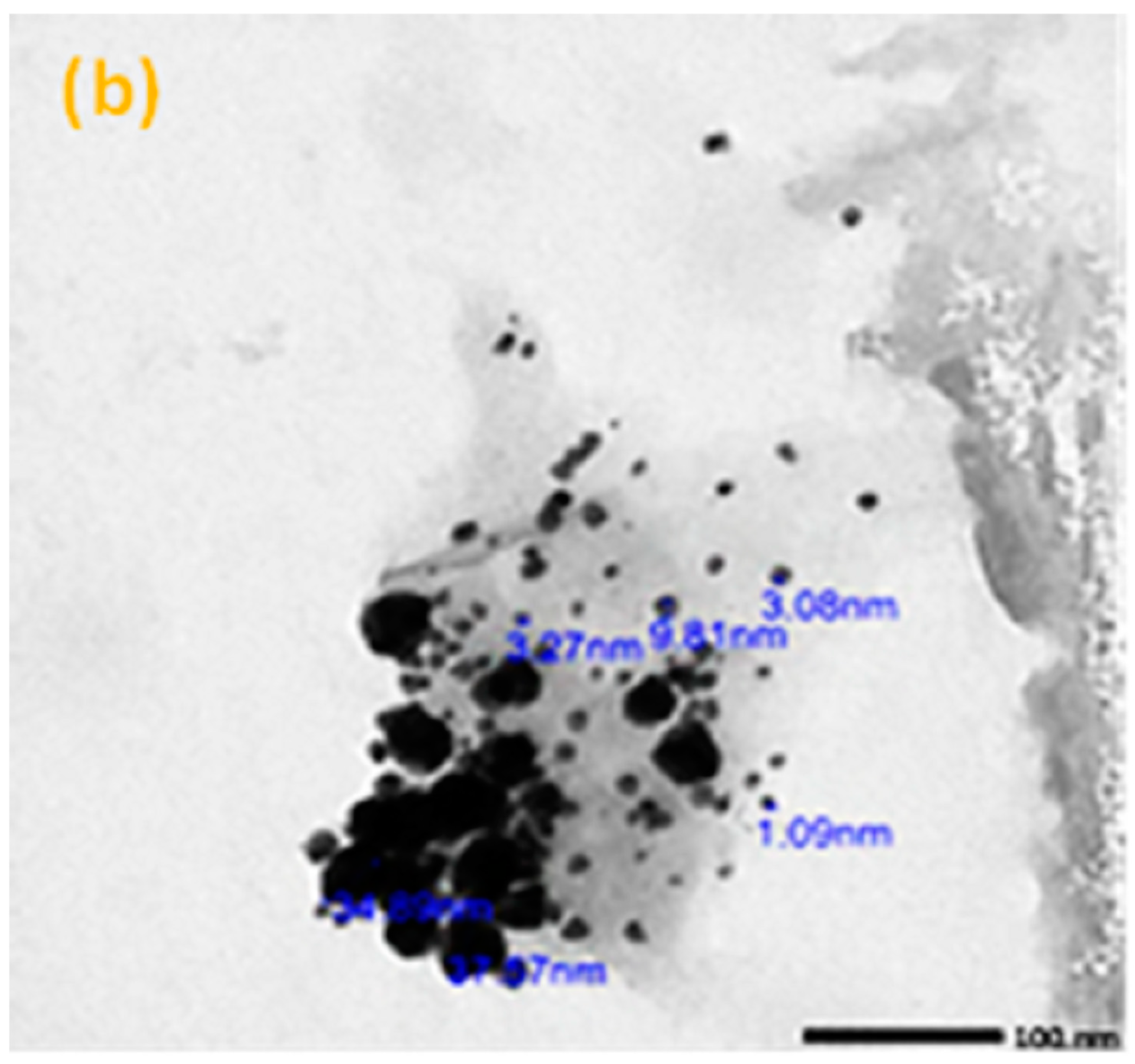
TEM analysis was carried out using a JEM-2100F transmission electron microscope with a 200 kV acceleration voltage to identify the particle sizes of the micro- and nano-sized Bi2O3. According to Figure 1a,b, the average size of the microparticles was 3 µm, while the nanoparticles were 12 nm. Scanning electron microscopy (SEM) (JEOL-JFC-1100E) can be used to determine the cross-section morphology and distribution of the Bi2O3 inside the samples. Figure 2 illustrates some images of the scanned samples using SEM for bentonite–gypsum, 6 wt% bulk of Bi2O3/bentonite–gypsum, 20 wt% bulk of Bi2O3/bentonite–gypsum, 6 wt% nano of Bi2O3/bentonite–gypsum, and 20 wt% nano of Bi2O3/bentonite–gypsum samples. As seen in Figure 2a, the SEM image of the blank sample was smooth and clear compared to the filled composites exhibited in Figure 2b–e. In Figure 2d,e, the nano-Bi2O3 particles have a more homogeneous distribution within the main matrix (bentonite–gypsum) than the micro-Bi2O3 particles, Consequently, the nano combination performed well in terms of protection.

2.4. Radiation Measurements

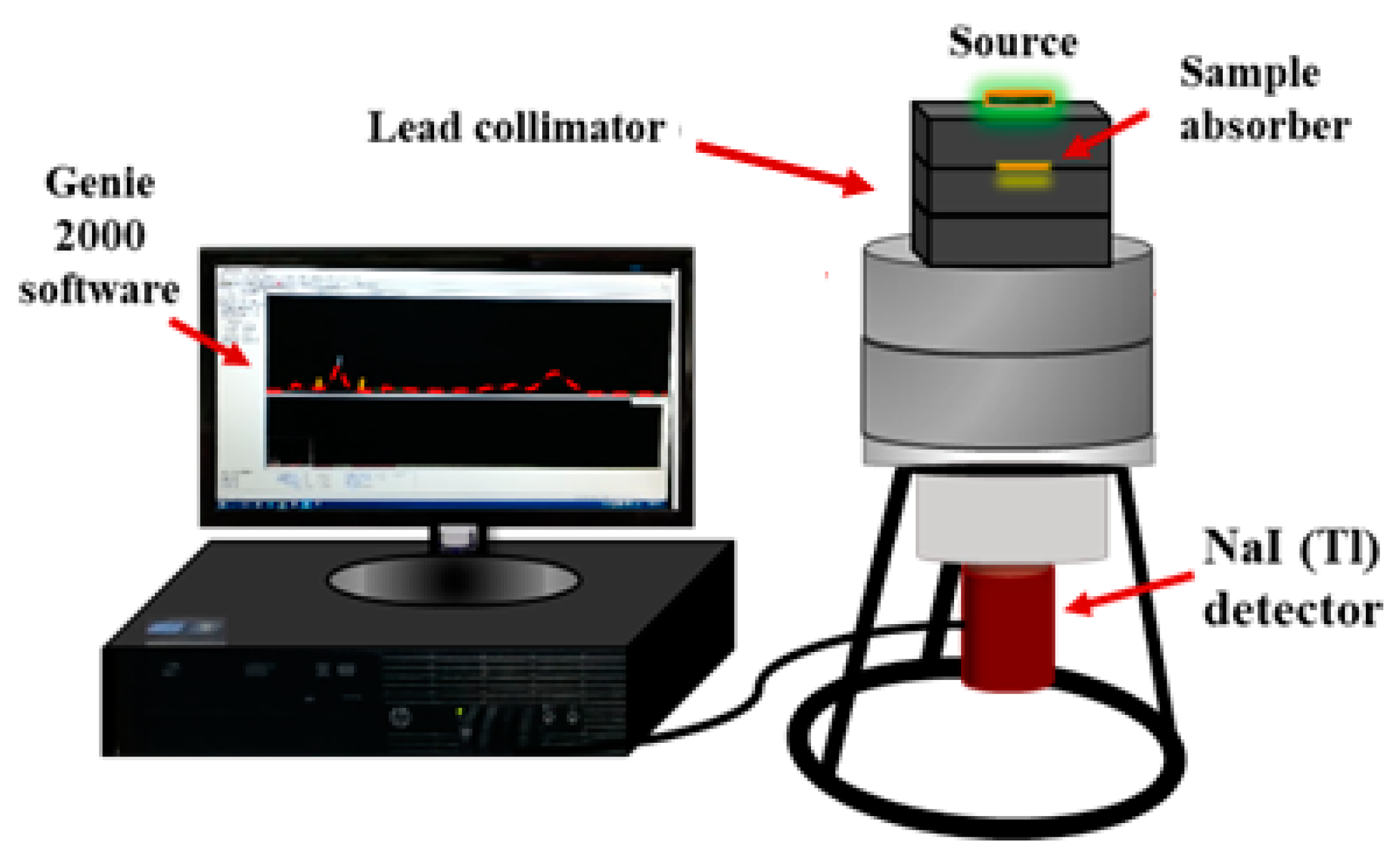
An experiment was carried out to determine the intensity of γ-rays that penetrated the sample and the shielding parameters. The gamma source provided a narrow beam that transmitted through the sample and reached the detector. The detector used in this experiment is a scintillation detector of the type NaI (Tl). Figure 3 shows the setup configuration of the source–detector system. Four radioactive sources were used in the present work: 241Am, 137Cs, 133Ba, and 60Co. These sources emit radiation of a wide range of energies, from 0.0595 MeV to 1.332 MeV. The photons that emerged from the sample interacted with the detector crystal, which converted them into signals and displayed them as peaks in a spectrum, via the Genie 2000 software [14,15,16,17,18].
To evaluate the capability of the material for shielding, the linear attenuation coefficients (LAC) were calculated by Beer-Lambert’s law [19]:
μ = 1 t ln ( I 0 I )
where μ is the linear attenuation coefficient (LAC), Io is the intensity of the incident gamma rays emitted from the radioactive source, I is the intensity of gamma rays after being attenuated in the presence of the absorber, and t is the sample thickness.
The half-value layer (HVL) is defined as the absorption thickness needed to decrease the incident radiation on the substance to 50% of its initial value when preparing a suitable substance for protection against radiation and is calculated using Equation (2) [20,21].
HVL = ln 2 μ
The tenth-value layer (TVL) is represented by the absorption thickness needed to decrease the incident radiation on the substance to 10% of its initial value [22,23].
TVL = ln 10 μ
The mean free path (MFP) is defined as the average distance at which the photon travels through the sample without any interaction.
MFP = 1 μ
The mass attenuation coefficient (μm) is a parameter that can be used widely in studying and comparing the efficiency of shielding different materials. It is used to measure the average number of radiation interactions with matter in a given mass thickness of the target material and is calculated by dividing the LAC of the sample by its density (⍴), as shown in the following equation [24,25].
μ m = μ ρ
The relative deviations for the measured mass attenuation coefficient compared to the XCOM result (∆1) and between the micro- and nano-measured results (∆2) are given by the following equations:
Δ 1 % = MAC XCOM   MAC Micro   MAC Micro × 100
Δ 2 % = MAC Nano     MAC Micro   MAC Micro × 100
The effective atomic number is computed by the following equation [26].
Z eff   = Σ I   I   I i   [ μ ρ ] i I w i   I [ μ ρ ] i
where Zi, Ai, and wi represent the atomic number, atomic weight, and the weight fraction of element ‘i’ in the composite, respectively.
The buildup factor is a correction factor (multiplicative factor) that concerns the scattered photons and the influences of the secondary particles in the medium during shielding calculations. As a result, the contributions of the scattered photons were included in this multiplicative factor. The calculation of buildup factors depends on the rate at which the photons flow through a medium and the number of interactions that occur. To calculate the energy absorption buildup (EABF) and exposure buildup (EBF) factors, the computation of the equivalent atomic number (Zeq) and the G–P fitting method are used for each tested composite [27,28]. Three steps should be undertaken for each composite, as follows:
(A) The computation of equivalent atomic number (Zeq):
The equivalent atomic number is energy dependent. It can be calculated by finding the ratio of Compton mass attenuation (µ/⍴), Compton, and the total mass attenuation coefficient (µ/⍴) for a given composite in the photon energy range from 0.015 to 15 MeV, using the WinXCom program [29]. The following equation is used to obtain Zeq:
z eq = z 1 ( log R 2 log R ) + z 2 ( log R log R 1   ) ( log R 2 log R 1 )
where Z1 and Z2 are the atomic numbers that correspond to R1 and R2, respectively. R is the ratio of the given composite at a particular energy.
(B) The calculation of the G–P fitting parameters:
Then, the G–P filling parameters (a, b, c, d, and Xk) will be obtained using the following interpolation equation.
b = b 1 ( log z 2 log z eq ) + b 2 ( log z eq log z 1 ) ( log z 2 log z 1 )
(C) The calculation of the buildup factor:
Finally, the buildup factors have been estimated using the following equations.
B   ( E ,   x ) = 1 + b 1 K 1 ( K x 1 ) ,   for   K     1
B (E, x) = 1+ (b − 1) x, for K = 1
K ( E , x ) = cx a + d tanh ( x X k 2 ) tan h ( 2 ) 1 tan h ( 2 ) ,   for   x   40   mfp
where K (E, x) is the variation corresponding to the change in energy, and E is the incident energy at the x mean free path.

3. Results and Discussion

The mass and linear attenuation coefficient values for the samples were determined for the photon energy range between 0.05953 MeV and 1.332 MeV. Table 3 shows the measured values and theoretical values using the XCOM of mass attenuation coefficients, linear attenuation coefficients, relative deviation, and density of pure bentonite–gypsum, micro-Bi2O3/bentonite–gypsum, and nano-Bi2O3/bentonite–gypsum composites.
Table 3 clearly shows that the mass attenuation coefficient (μm) decreases with increasing photon energy and increases with increasing bismuth oxide Bi2O3 in the sample. The mass attenuation coefficients (μm) of the samples are notable for having a large value at a photon energy of 0.05953 MeV and then decreasing gradually as the photon energy increased. This behavior can be related to the photon partial interaction process. At low photon energies (e.g., about 0.05953 MeV), the attenuation values follow the photoelectric absorption, which is inversely proportional to E3. At intermediatory energy, Compton scattering dominates the attenuation process, and the attenuation is inversely proportional to E (for example, at energy 59.53 keV, the photon cross-sections for photoelectric absorption and Compton scattering for BG-5Micro are 1.008 and 0.143 cm2/g, respectively, while at an energy of 661.66 keV, they are 0.008 and 0.074 cm2/g, respectively. Mass attenuation values are nearly constant for the energies equal to or higher than 1.022 MeV because the pair production process is dominant in this region. It is obvious that the attenuation ability of the sample relates to the composition of the sample, such that the gamma photons cause higher attenuation as the bismuth oxide (Bi2O3) amount in the sample increases. Further, according to Table 3, as the Bi2O3 content in the samples increases, the mass density increases, reaching 2.815 ± 0.03 g cm−3 in the BG-5Micro sample. The larger molecular weight and the higher photon–electron interactions of Bi2O3, increase the linear attenuation coefficient value with Bi2O3 for each energy under investigation.
The influence of Bi2O3 in micro- and nanoscales on the mass and linear attenuation coefficients for different samples were also studied. The higher MAC and LAC values for Bi2O3 NPs than for the bulk Bi2O3 are due to the distribution of particles in the sample. The smaller size of the NPs allows for a more uniform distribution of particles within the sample, thus, increasing the surface–mass ratio, and resulting in a higher probability of interaction between the Bi2O3 NPs and the gamma photons. As a result, the attenuation capabilities of the Bi2O3 NP sample are better than those of the Bi2O3 bulk sample. Moreover, Table 3 shows that the relative deviation (∆1%) between the theoretical values (XCOM) and the experimental micro values range between −3.72 and 2.74%, which confirms the precision of the results. The relative deviation (∆2%) between the experimental nano and micro values ranges between 4.7 and 16.9%, confirming that the nanoparticles improve the attenuation efficiency.
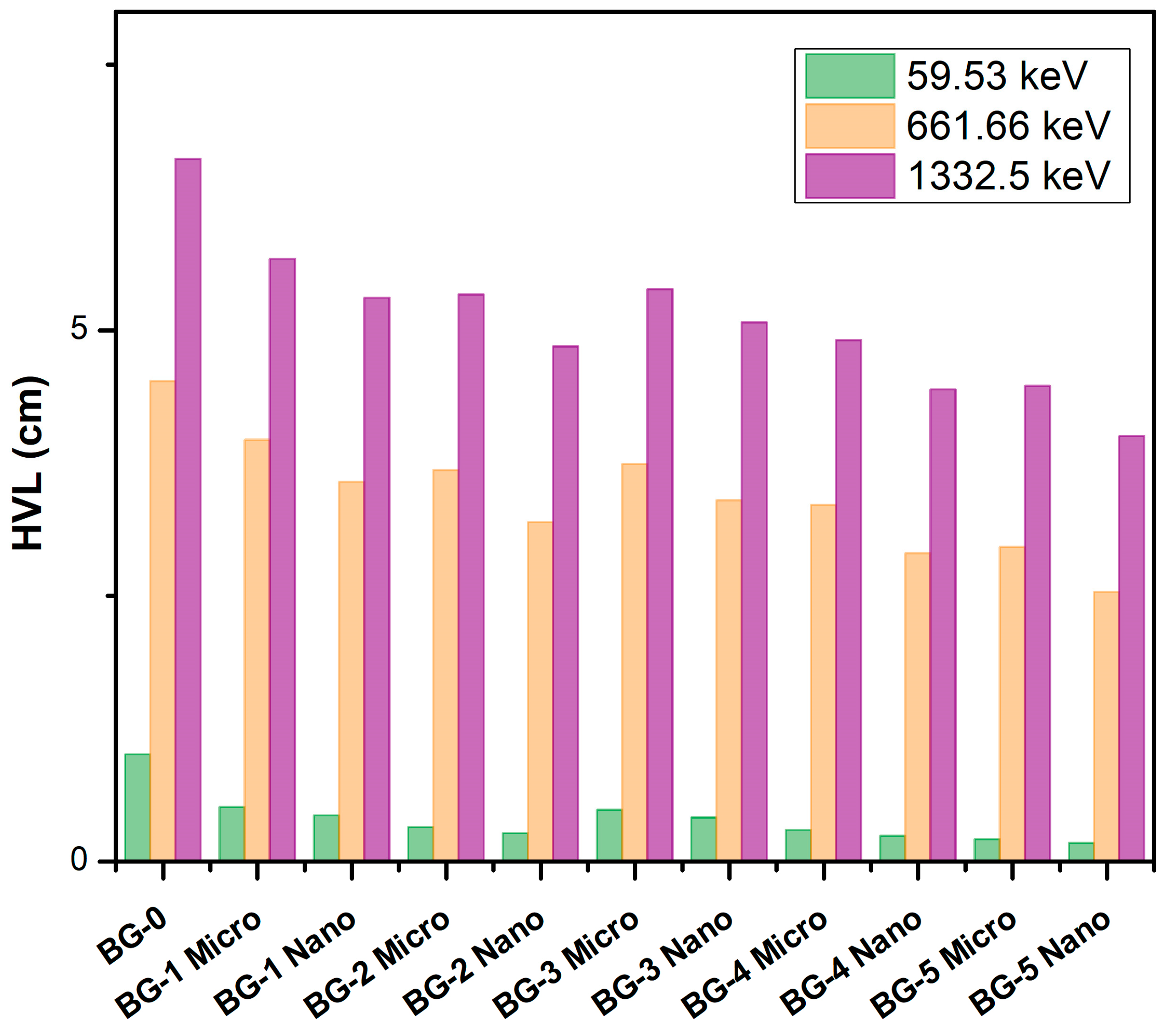
The half-value layer values provide certain information about the shielding capability of the sample against the gamma photons (the lower the HVL, the higher the shielding efficiency). Figure 4 shows the HVL for the compositions at photon energies of 59.53, 661.66, and 1332.5 keV. The HVL for the BG-0 sample tends to increase regularly in the examined energy range. For instance, the HVL regularly rises from 1.01 cm at 59.53 keV to 4.52, and 6.61 cm at 661.66, and 1332.5 keV, respectively. The same trend is observed for the remaining samples. Furthermore, it was realized that the HVL values of BG-5, which contains 20 wt% of the bulk and NPs Bi2O3, have much lower values than the HVL of the BG-0, BG-1, BG-2, BG-3, and BG-4 samples at the same photon energies. Therefore, the greater the amount of bismuth oxide (Bi2O3) content plays an important factor in reducing the half-value layer of the investigated samples. Moreover, it was noted that the HVL levels for the nano-Bi2O3/bentonite–gypsum composites are much lower than those of micro-Bi2O3/bentonite–gypsum composites, which have the same weight percentage of bentonite, gypsum, and Bi2O3 at the same photon energies. For example, at a photon energy of 59.53 keV, the HVL of the BG-1Nano (0.44 cm) < BG-1Micro (0.54 cm), BG-2Nano (0.27 cm) < BG-2Micro (0.33 cm), BG-3Nano (0.42 cm) < BG-3Micro (0.49 cm), BG-4Nano (0.24 cm) < BG-4Micro (0.3 cm), and BG-5Nano (0.18 cm) < BG-5Micro (0.21 cm). Thereby indicating the higher performance of the nanocomposites at shielding against radiation. Furthermore, when the samples with the same Bi2O3 concentrations but different gypsum concentrations are compared, it is notable that the higher concentrations of gypsum equate to lower HVL values at the same photon energies because gypsum has a higher density than bentonite.
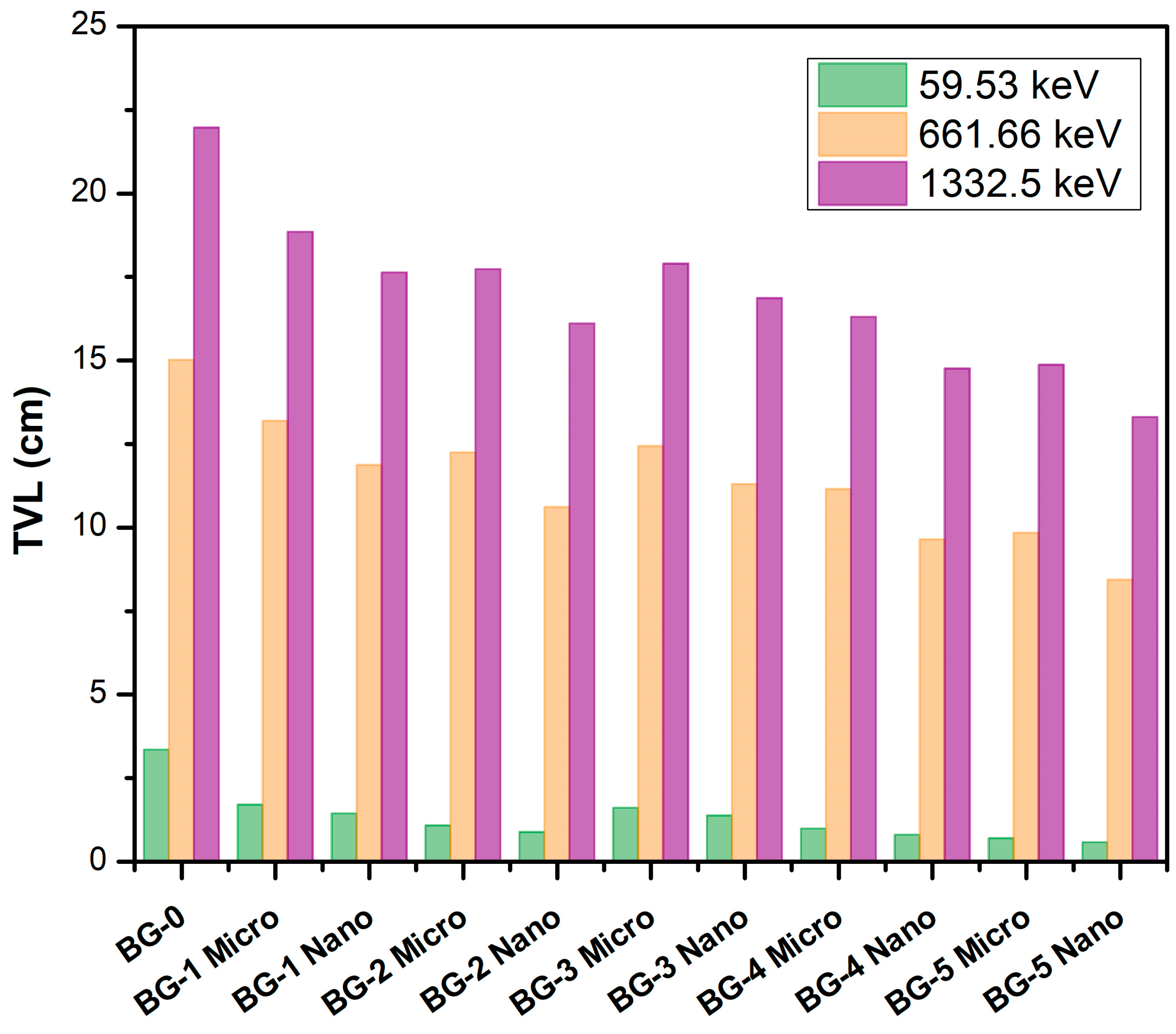
Figure 5 shows the TVL, which is energy dependent, for the composites of Bi2O3/bentonite–gypsum. It is obvious that as the photon energy increases, so do the TVL values, and more shielding material thickness is required to reduce the intensity of the incident γ-ray to one-tenth of its initial value. For example, the HVL of the BG-0 sample increases from 3.36 cm, at 59.53 keV, to 15.02 cm, at 661.66 keV, and 21.97 cm at 1332.5 keV. Moreover, this figure shows the greatest tenth-value layer for BG-0, which is a pure bentonite–gypsum sample without any Bi2O3. By adding different amounts of Bi2O3 (6 wt%, 13 wt%, and 20 wt%) to the bentonite–gypsum matrix, the values of the tenth-value layer decrease. At 59.53 keV, for example, the TVL values are equal to 3.36 cm, 1.71 cm, 1.09 cm, and 0.70 cm for BG-0, BG-1Micro, BG-2Micro, and BG-5Micro, respectively. Furthermore, the particle size influences the tenth-value layer values, with nano-Bi2O3/bentonite–gypsum samples having lower TVL values at the same photon energies as the micro-Bi2O3/bentonite–gypsum samples. When the samples with the same concentrations of Bi2O3, yet with a higher concentration of gypsum were compared, it was discovered that the ones with the higher gypsum concentration presented lower TVL values.
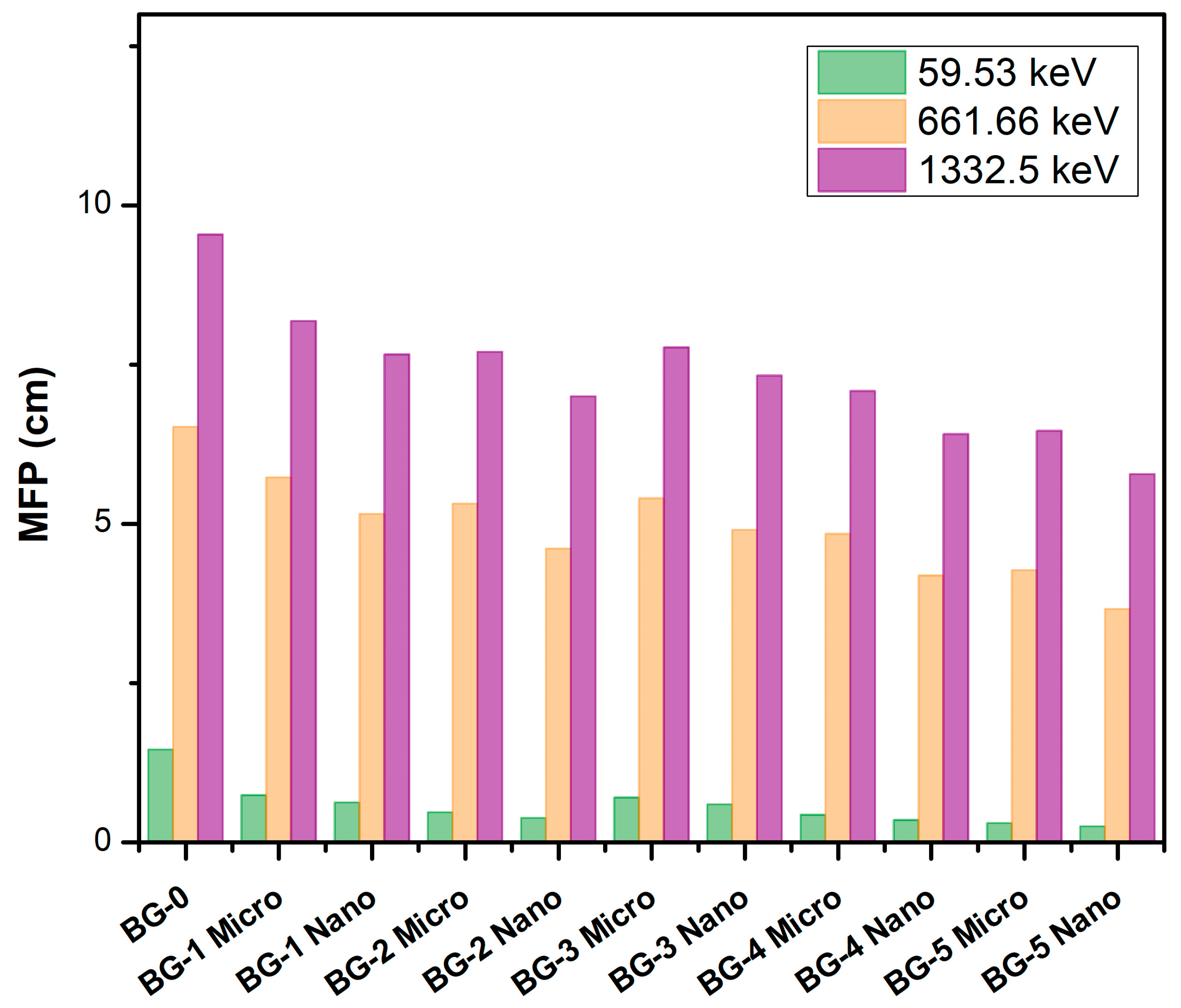
The MFPs of the Bi2O3/bentonite–gypsum composites for photon energies of 59.53, 661.66, and 1332.5 keV are shown in Figure 6. The mean free path is small when the photon energy is low, and it increases as the photon energy increases. The MFP for the BG-0 sample increased from 1.46 cm to 9.54 cm when the photon energy varied from 59.53 keV to 1332.5 keV, and the MFP for the BG-5Micro sample increased from 0.31 cm to 6.46 for the same respective energies. Therefore, in the application, it is recommended to increase the sample thickness because the high photon energy can penetrate deeper in the sample. Additionally, the increment of the Bi2O3 content in the sample was shown to improve the shielding efficiency of the sample. For example, at 59.53 keV, the MFP values are equal to 1.46 cm, 0.74 cm, 0.47 cm, and 0.31 cm for the BG-0, BG-1Micro, BG-2Micro, and BG-5Micro samples, respectively. This is because at low photon energies, the photoelectric absorption interaction depends on the atomic number to the power four (Z4), while at high photon energies, the Compton scattering interaction relates to the atomic number (Z). The photon interaction probability increases as the atomic number (Z) increases. This means that the attenuation of photons will increase, leading to a decrease in the MFP of the used sample [30].
Another important parameter that can be used to explain the different characteristics of the material is the effective atomic number (Zeff). Table 4 lists the calculated Zeff values (using Equation (8)) for the bentonite–gypsum specimens fixed with Bi2O3 at γ-ray energies in the range of 59.53–1332.50 keV. The Zeff of the composite depends on the relative portion of the Z values of the constituent elements of each sample. By comparing the values of BG-1, which contains a smaller amount of Bi2O3, with BG-5, which contains the largest amount of Bi2O3, it was observed that the BG-5 Zeff possessed higher values than that of BG-1, at the same γ-ray energies. Moreover, samples with the same Bi2O3 concentration and a higher amount of gypsum showed higher Zeff values than those with smaller gypsum amounts. Where Zeff of BG-1 < BG-3 and BG-2 < BG-4 at the same γ-ray energies.
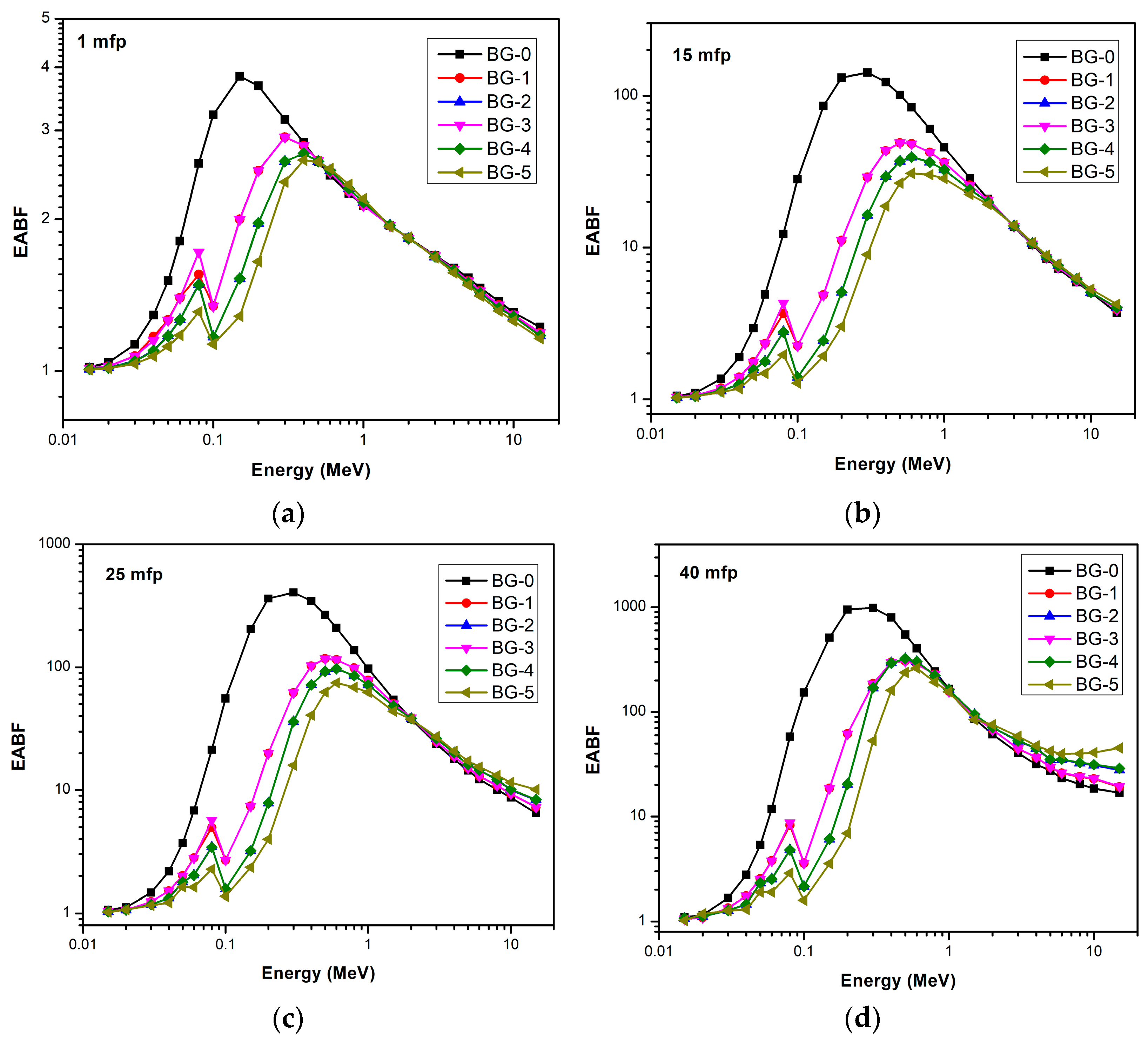
The equivalent atomic number (Zeq) for bentonite–gypsum with Bi2O3 as a filler was calculated between 0.015 and 15 MeV of photon energy. After that, the EABF and EBF were calculated for all composites using the G–P fitting parameters. Figure 7 and Figure 8 represent the variation of EABF and EBF for bismuth oxide bentonite–gypsum, with photon energies for different penetration depths. It is clear that the lowest buildup factor values occur for composites that contain a higher amount of Bi2O3 at a constant mfp. Moreover, it is obvious that for all composites, as the mfp values increase, the buildup factor values rise, showing maximum buildup factor values at 40 mfp.
The variation in buildup factors with energy is because in lower photon energy regions, photoelectric absorption dominates, and in higher photon energy regions, pair production dominates. In the intermediate photon energy range, where Compton scattering dominates, the buildup factor increases. The multiple Compton scattering events increase the buildup factors to reach the maximum values. At the pair production region, the higher the penetration depth, the lower the buildup factor, where it reaches a minimum value. The sudden increase in the behavior of the buildup factor at lower energies is due to the K-edge of the bismuth oxide. The K-edge is a phenomenon that describes a sudden increase in the attenuation coefficient of photons when the energy of the incident photons becomes slightly more than the binding energy of the K-shell electron of the atoms interacting with those photons.
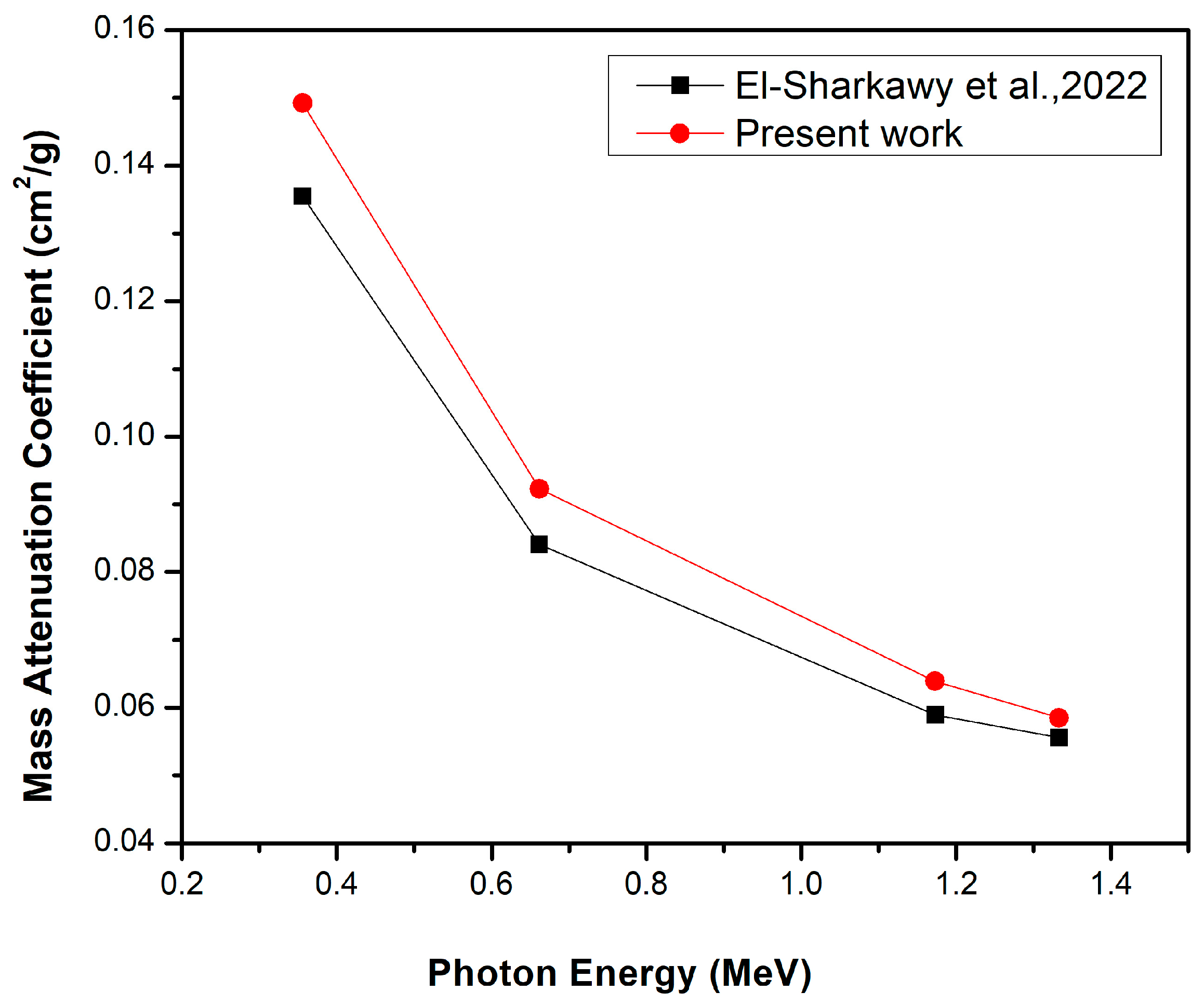
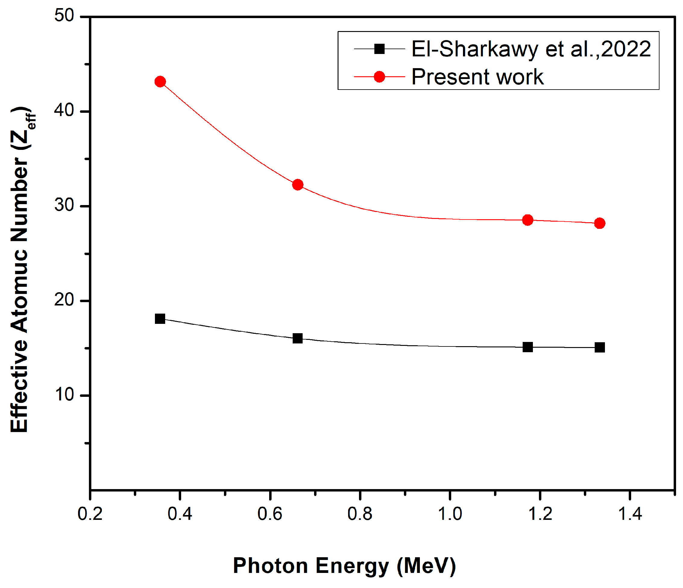
Comparison of this study, which uses a bentonite–gypsum matrix and Bi2O3 NPs (filler), with El-Sharkawy et al. [31], where nanoscale Bi2O3 was used as filler in a bentonite matrix, at the same Bi2O3 NP concentrations and photon energies, highlighted that some elements in the bentonite of the present work were not found in the specimens used byEl-Sharkawy et al., such as magnesium, potassium, titanium, and iron, in addition to the chemical composition of gypsum. Consequently, the bentonite–gypsum composites used in the current work for the 20 wt% Bi2O3 NPs have a higher mass attenuation coefficient (red line) than the bentonite matrix composite used in El-Sharkawy et al. [31] (black line); see Figure 9. This means that the presence of these elements and gypsum in the nanocomposites increases the mass attenuation coefficient, which confirms the higher shielding performance of bentonite in the nano-Bi2O3 composites. Moreover, it was observed that the effective atomic number of the present work (red line) is larger than that produced by El-Sharkawy et al. [31] (black line) for the 20 wt% NP- Bi2O3, see Figure 10 for the same reason.

4. Conclusions

Bentonite and gypsum are used in this study as the main matrix because of their characteristics. Bismuth oxide (Bi2O3) is used in this paper as a filler with various weight percentages (6, 13, and 20) in bulk and nanosized particles to produce new bentonite-based bulk and nanocomposite radiation shielding materials. The experimental values of the mass attenuation coefficient were determined and compared with the theoretical XCOM ones, giving good comparability of the results. It was observed that the specimens with a higher weight percentage of Bi2O3 showed higher mass attenuation coefficients. Moreover, the specimens that contain nanoscale Bi2O3 have much higher mass attenuation coefficients compared with the same percentages of the main matrix and filler bulk Bi2O3, at the same photon energies. Furthermore, the greater the amount of gypsum, the greater the mass attenuation coefficient for all weight percentages of Bi2O3 at different γ-ray photon energies, ranging from 0.0595 MeV to 1.3325 MeV. The HVL, TVL, MFP, and Zeff values confirm the results that were obtained from the mass attenuation coefficient. The EABF and EBF, for all investigated composites, increase at low photon energies until they reach maximum values at intermediate photon energies, then, they decline at high photon energies. Moreover, the larger amounts of bismuth oxide composite show lower absorptions and exposure buildup factors. Finally, the greater the penetration depth, the higher the EABF and EBF values.

Author Contributions

Conceptualization, A.M.E.-K.; Methodology, S.N.E.-S.; Software, M.E.; Validation, H.M.A.; Formal analysis, M.I.A., H.M.A. and M.M.G.; Investigation, M.F.D.; Resources, R.B.; Data curation, R.B.; Writing—original draft, S.N.E.-S. and M.F.D.; Writing—review & editing, A.M.E.-K. and M.M.G.; Visualization, M.M.G.; Supervision, M.I.A. and A.M.E.-K. All authors have read and agreed to the published version of the manuscript.

Funding

This research received no external funding.

Institutional Review Board Statement

Not applicable.

Informed Consent Statement

Not applicable.

Data Availability Statement

All data are available in the manuscript.

Conflicts of Interest

The authors declare no conflict of interest.

References

  1. Kavaz, E.; Ghanim, E.H.; Abouhaswa, A.S. Optical, structural and nuclear radiation security properties of newly fabricated V2O5-SrO-PbO glass system. J. Non Cryst. Solids 2020, 538, 120045. [Google Scholar] [CrossRef]
  2. Agar, O.; Khattari, Z.Y.; Sayyed, M.I.; Tekin, H.O.; Al-Omari, S.; Maghrabi, M.; Zaid, M.H.M.; Kityk, I.V. Evaluation of the shielding parameters of alkaline earth based phosphate glasses using MCNPX code. Result. Phys. 2019, 12, 101–106. [Google Scholar] [CrossRef]
  3. Sayyed, M.I.; Almuqrin, A.H.; Kurtulus, R.; Javier-Hila, A.V.; Kaky, K.; Kavas, T. X-ray shielding characteristics of P2O5–Nb2O5 glass doped with Bi2O3 by using EPICS2017 and Phy-X/PSD. Appl. Phys. A 2021, 127, 243. [Google Scholar] [CrossRef]
  4. Sayyed, M.I.; Al-Hadeethi, Y.; AlShammari, M.M.; Ahmed, S.H.; Rammah, Y.S. Physical, optical and gamma radiation shielding competence of newly borotellurite based glasses: TeO2–B2O3–ZnO–Li2O3–Bi2O3. Ceram. Int. 2021, 47, 611–618. [Google Scholar] [CrossRef]
  5. Ozdogan, H.; Kilicoglu, O.; Akman, F.; Agar, O. Comparison of Monte Carlo simulations and theoretical calculations of nuclear shielding characteristics of various borate glasses including Bi, V, Fe, and Cd. Appl. Radiat. Isot. 2022, 189, 110454. [Google Scholar] [CrossRef] [PubMed]
  6. Çakıroğlu, M.; Kaplan, A.; Süzen, A. Experimental and DBN-Based neural network extraction of radiation attenuation coefficient of dry mixture shotcrete produced using different additives. Radiat. Phys. Chem. 2021, 188, 109636. [Google Scholar] [CrossRef]
  7. Akman, F.; Khattari, Z.Y.; Kaçal, M.R.; Sayyed, M.I.; Afaneh, F. The radiation shielding features for some silicide, boride and oxide types ceramics. Radiat. Phys. Chem. 2019, 160, 9–14. [Google Scholar] [CrossRef]
  8. Tiamduangtawan, P.; Kamkaew, C.; Kuntonwatchara, S.; Wimolmala, E.; Saenboonruang, K. Comparative mechanical, self-healing, and gamma attenuation properties of PVA hydrogels containing either nano- or micro-sized Bi2O3 for use as gamma-shielding materials. Radiat. Phys. Chem. 2020, 177, 109164. [Google Scholar] [CrossRef]
  9. Intom, S.; Kalkornsurapranee, E.; Johns, J.; Kaewjaeng, S.; Kothan, S.; Hongtong, W.; Chaiphaksa, W.; Kaewkhao, J. Mechanical and radiation shielding properties of flexible material based on natural rubber/Bi2O3 composites. Radiat. Phys. Chem. 2020, 172, 108772. [Google Scholar] [CrossRef]
  10. Kurtuluş, R.; Buriahi, M.S.; Issa, S.A.M.; Tekin, H.O.; Kavas, T.; Kavaz, E. Physical, structural, mechanical and radiation shielding features of waste pharmaceutical glasses doped with Bi2O3. Optik 2022, 261, 169108. [Google Scholar] [CrossRef]
  11. Luchechko, A.; Vasyltsiv, V.; Kostyk, L.; Tsvetkova, O.; Popov, A.I. Shallow and deep trap levels in X-ray irradiated β-Ga2O3: Mg. Nucl. Instrum. Methods Phys. Res. Sect. B Beam Interact. Mater. At. 2019, 441, 12–17. [Google Scholar] [CrossRef]
  12. Averback, R.S.; Ehrhart, P.; Popov, A.I.; Sambeek, A.V. Defects in ion implanted and electron irradiated MgO and Al2O3. Radiat. Eff. Defects Solids 1995, 136, 169–173. [Google Scholar] [CrossRef]
  13. Kiatwattanacharoen, S.; Srimaroeng, P.; Kothan, S.; Jumpee, C.; Kim, H.J.; Kaewjaeng, S. A study of X-ray Radiation Shielding Properties of Bricks Contained Barium Sulfate. AIP Conf. Proc. 2020, 2279, 060004. [Google Scholar]
  14. Gouda, M.M.; Badawi, M.S.; El-Khatib, A.M.; Hussien, N.S.; Abbas, M.I. Calculation of NaI(Tl) Detector Full-Energy Peak Efficiency Using the Efficiency Transfer Method For Small Radioactive Cylindrical Sources. Nucl. Technol. Radiat. Prot. J. 2016, 31, 150–158. [Google Scholar] [CrossRef] [Green Version]
  15. Badawi, M.S.; Ruskov, I.; Gouda, M.M.; El-Khatib, A.M.; Alotiby, M.F.; Mohamed, M.M.; Thabet, A.A.; Abbas, M.I. A numerical approach to calculate the full-energy peak efficiency of HPGe well-type detectors using the effective solid angle ratio. J. Instrum. 2014, 9, P07030. [Google Scholar] [CrossRef]
  16. Abd-Elzaher, M.; Badawi, M.S.; El-Khatib, A.M.; Thabet, A.A. Determination of full energy peak efficiency of NaI (Tl) detector depending on efficiency transfer principle for conversion form experimental values. World J. Nucl. Sci. Technol. 2012, 2, 3. [Google Scholar] [CrossRef] [Green Version]
  17. Gouda, M.M. Calibration of NaI (Tl) Cylindrical Detector Using Axially Shifted Radioactive Cylindrical Sources. Nucl. Technol. Radiat. Prot. 2019, 34, 353–360. [Google Scholar] [CrossRef] [Green Version]
  18. Badawi, M.S.; Gouda, M.M.; Nafee, S.S.; El-Khatib, A.M.; El-Mallah, E.A. New algorithm for studying the effect of self attenuation factor on the efficiency of γ-rays detectors. Nucl. Instrum. Methods Phys. Res. Sect. A Accel. 2012, 696, 164–170. [Google Scholar] [CrossRef]
  19. El-Khatib, A.M.; Abbas, M.I.; Sayyed, M.I.; Khandaker, U.; Abd-Elzaher, M.; Khalil, M.M.; Elsafi, M.; Gouda, M.M. Assessment of γ-radiation shielding behavior of some mixed nature clays. Radiat. Phys. Chem 2022, 200, 110236. [Google Scholar] [CrossRef]
  20. El-Khatib, A.M.; Abbas, A.M.; Hammoury, S.I.; Gouda, M.M.; Zard, K.; Elsafi, M. Effect of PbO-Nanoparticles on Dimethyl Polysiloxane for use in Radiation Shielding Applications. Sci. Rep. 2022, 12, 15722. [Google Scholar] [CrossRef]
  21. Elsafi, M.; Sayyed, M.I.; Almuqrin, A.H.; Gouda, M.M.; El-Khatib, A.M. Analysis of particle size on mass dependent attenuation capability of bulk and nanoparticle PbO radiation shields. Results Phys. 2021, 26, 104458. [Google Scholar] [CrossRef]
  22. Elsafi, M.; Shehata, A.G.; El-Khatib, A.M.; Abbas, A.M.; Sayyed, M.I.; Khandaker, M.U.; Gouda, M.M. Effect of iron and ferrosilicon materials to enhance the radiation shielding ability of bentonite clay. Radiat. Phys. Chem. 2022, 110235. [Google Scholar] [CrossRef]
  23. Gouda, M.M.; Abbas, A.M.; Hammoury, S.I.; Zard, K.; El-Khatib, A.M. Nano tin oxide/dimethyl polysiloxane reinforced composite as a flexible radiation protecting material. Sci. Rep. 2023, 13, 210. [Google Scholar] [CrossRef] [PubMed]
  24. Kumar, A.; Lingfa, P. Sodium bentonite and kaolin clays: Comparative study on their FT-IR, XRF, and XRD. Mater. Today: Proc. 2020, 22, 737–742. [Google Scholar] [CrossRef]
  25. El-Khatib, A.M.; Doma, A.S.; Badawi, M.S.; Abu-Rayan, A.E.; Aly, N.S.; Alzahrani, J.S.; Abbas, A.M. Conductive natural and waste rubbers composites-loaded with lead powder as environmental flexible gamma radiation shielding material. Mater. Res. Express 2020, 7, 105309. [Google Scholar] [CrossRef]
  26. Kurudirek, M. Effective atomic numbers and electron densities of some human tissues and dosimetric materials for mean energies of various radiation sources relevant to radiotherapy and medical applications. Radiat. Phys. Chem. 2014, 102, 139–146. [Google Scholar] [CrossRef]
  27. Sharaf, J.M.; Saleh, H. Gamma-ray energy buildup factor calculations and shielding effects of some Jordanian building structures. Radiat. Phys. Chem 2015, 110, 87–95. [Google Scholar] [CrossRef]
  28. Alabsy, M.T.; Alzahrani, J.S.; Sayyed, M.I.; Abbas, M.I.; Tishkevich, D.I.; El-Khatib, A.M.; Elsafi, M. Gamma-Ray Attenuation and Exposure Buildup Factor of Novel Polymers in Shielding Using Geant4 Simulation. Materials 2021, 14, 5051. [Google Scholar] [CrossRef]
  29. Berger, M. XCOM: Photon cross Section Database (Version 1.3). 2005. Available online: https://physics.nist.gov/xcom (accessed on 28 September 1998).
  30. Alsayed, Z.; Badawi, M.S.; Awad, R.; Thabet, A.A.; El-Khatib, A.M. Study of some γ-ray attenuation parameters for new shielding materials composed of nano ZnO blended with high density polyethylene. Nucl. Technol. Radiat. Prot. 2019, 34, 342–352. [Google Scholar] [CrossRef] [Green Version]
  31. El-Sharkawy, R.M.; Allam, E.A.; El-Taher, A.; Elsaman, R.; Massoud, E.E.; Mahmoud, M.E. Synergistic effects on gamma-ray shielding by novel light-weight nanocomposite materials of bentonite containing nano Bi2O3 additive. Ceram. Int. 2022, 48, 7291–7303. [Google Scholar] [CrossRef]
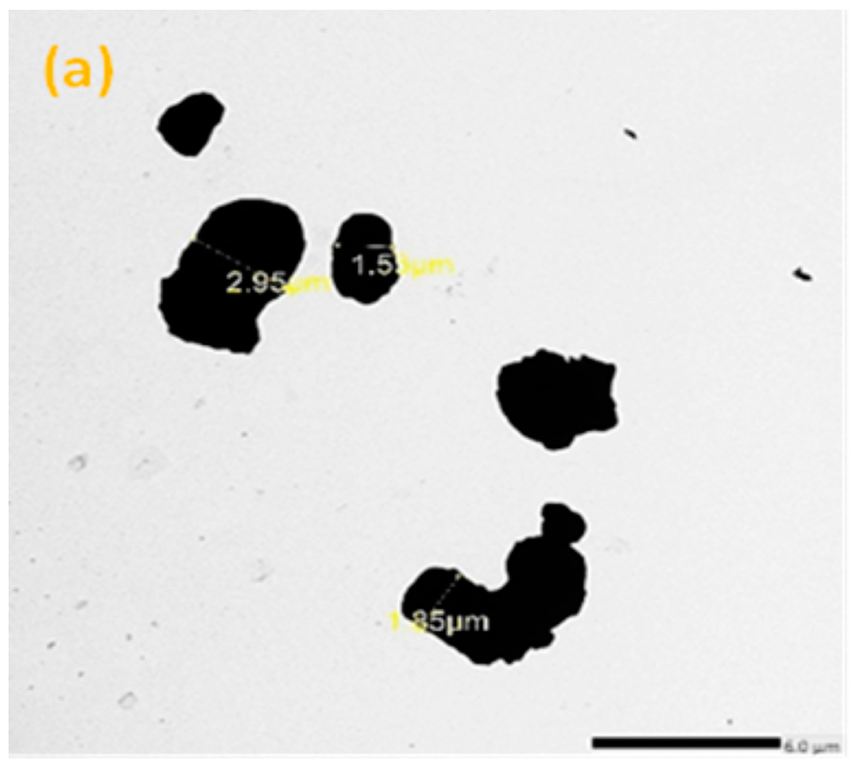
Figure 1. The TEM image of (a) micro-Bi2O3 particles, (b) nano-Bi2O3 particles.
Materials 16 02056 g001aMaterials 16 02056 g001b
Figure 2. SEM images of (a) BG-0, (b) BG-1Micro, (c) BG-5Micro, (d) BG-1Nano, (e) BG-5 Nano.
Materials 16 02056 g002
Figure 3. The experimental setup configuration of the sample with respect to the radioactive source and the detector.
Materials 16 02056 g003
Figure 4. The half-value layer (HVL) of the Bi2O3/bentonite–gypsum composites at photon energies 59.53, 661.66, and 1332.5 keV.
Materials 16 02056 g004
Figure 5. The tenth-value layer (TVL) of the Bi2O3/bentonite–gypsum composites at photon energies of 59.53, 661.66, and 1332.5 keV.
Materials 16 02056 g005
Figure 6. The mean free path of the Bi2O3/bentonite–gypsum composites at photon energies 59.53, 661.66, and 1332.5 keV.
Materials 16 02056 g006
Figure 7. EABF as a function of photon energy at (a) 1mfp, (b)15 mfp, (c) 25 mfp, and (d) 40 mfp for bismuth oxide bentonite–gypsum.
Materials 16 02056 g007
Figure 8. EBF as a function of photon energy at (a) 1mfp, (b)15 mfp, (c) 25 mfp, and (d) 40 mfp for bismuth oxide bentonite–gypsum.
Materials 16 02056 g008
Figure 9. The comparison between the mass attenuation coefficient of 20 wt% nano-Bi2O3 in bentonite–gypsum matrix and the 20 wt% nano-Bi2O3 in the bentonite matrix only (Ref. [31]).
Materials 16 02056 g009
Figure 10. The effective atomic number of the present work (red line) and the effective atomic number of El-Sharkawy et al. (back line) [31], for the same 20 wt% Bi2O3 NPs.
Materials 16 02056 g010
Table 1. Chemical composition of bentonite and gypsum.
Metal OxideWeight Fraction (%)
BentoniteGypsum
Na2O1.300
MgO1.180
Al2O320.350
SiO249.650
SO31.9641.27
K2O1.280
CaO10.9258.73
TiO22.740
FeO10.620
Table 2. The sample codes and the weight fraction in percentage (wt%) of bentonite, gypsum, and Bi2O3.
Sample CodesCompositions (wt %)
Main MatrixBismuth Oxide (Bi2O3)
BentoniteGypsum
BG-067330
BG-1276
BG-22013
BG-361336
BG-45413
BG-556.723.320
Table 3. Measured values and theoretical values using the XCOM program of mass attenuation coefficients, linear attenuation coefficients, relative deviation, and density of pure bentonite–gypsum, micro-Bi2O3/bentonite–gypsum, and nano-Bi2O3/bentonite–gypsum composites.
Sample Code/wt%Energy (keV)Mass Attenuation Coefficient (cm2 g−1)Linear Attenuation Coefficient (cm−1)Density (g cm−3)
(MAC)XCOM(MAC)Micro 1 %(MAC)Nano 2 %(LAC)Micro(LAC)NanoMicroNano
BG-0
0 wt %
59.530.35800.35221.647 0.6861 1.948 ± 0.01
80.990.22380.22151.0380.4315
356.010.09930.09791.4300.1907
661.660.07660.0787−2.6680.1533
1173.230.05830.0586−0.5120.1142
1332.50.05470.05381.6730.1048
BG-1
6 wt %
59.530.60180.58582.7310.677215.6031.34731.59012.300 ± 0.022.348 ± 0.01
80.990.32560.3277−0.6410.363110.8030.75370.8526
356.010.10870.1104−1.5400.11837.1560.25390.2778
661.660.07810.07592.8990.08268.8270.17460.1939
1173.230.05840.05712.2770.06076.3050.13130.1425
1332.50.05470.05313.0130.05564.7080.12210.1305
BG-2
13 wt %
59.530.88630.86462.5101.005116.2502.11392.58312.445 ± 0.032.570 ± 0.02
80.990.44420.43292.6100.493213.9291.05841.2675
356.010.11960.11702.2220.130111.1970.28610.3344
661.660.07990.07693.9010.08449.7530.18800.2169
1173.230.05850.05722.2730.06137.1680.13990.1575
1332.50.05470.05313.0130.05564.7080.12980.1429
BG-3
6 wt %
59.530.60490.60080.6820.695415.7461.42091.66552.365 ± 0.022.395 ± 0.02
80.990.32670.32091.8070.370415.4250.75890.8871
356.010.10880.10681.8730.130422.0970.25260.3123
661.660.07820.0783−0.1280.08518.6850.18520.2038
1173.230.05840.0595−1.8490.06366.8910.14070.1523
1332.50.05470.05440.5510.05704.7790.12870.1365
BG-4
13 wt %
59.530.89300.9128−2.1691.060916.2252.30942.82942.530 ± 0.022.667 ± 0.03
80.990.44670.4512−0.9970.513713.8521.14151.3700
356.010.11980.1213−1.2370.134811.1290.30690.3595
661.660.08000.0816−1.9610.08959.6810.20640.2387
1173.230.05860.05722.4480.06167.6920.14470.1643
1332.50.05480.0558−1.7920.05854.8390.14120.1560
BG-5
20 wt %
59.531.17601.16321.1001.328614.2193.27443.93002.815 ± 0.032.958 ± 0.01
80.990.56490.54833.0280.620413.1501.54351.8351
356.010.13060.1324−1.3600.149212.6890.37270.4413
661.660.08180.0831−1.5640.092311.0710.23390.2730
1173.230.05870.05811.0330.06399.9830.16360.1890
1332.50.05470.0550−0.5450.05856.3640.15480.1730
Table 4. The effective atomic number (Zeff) of all tested specimens.
Energy
(keV)
BG-0BG-1BG-2BG-3BG-4BG-5
59.5317.194349.518362.700749.642062.944069.1968
80.9915.659742.752856.724242.796656.842764.3237
356.0113.375724.687234.962024.767135.113743.1547
661.6613.339019.466326.059019.554826.242732.2615
1173.2313.332318.007023.281618.097823.474828.5231
1332.5013.334617.893023.056117.983923.249828.2105
Disclaimer/Publisher’s Note: The statements, opinions and data contained in all publications are solely those of the individual author(s) and contributor(s) and not of MDPI and/or the editor(s). MDPI and/or the editor(s) disclaim responsibility for any injury to people or property resulting from any ideas, methods, instructions or products referred to in the content.