Abstract
The thermal stability of the polyethylene (PE) separator is of utmost importance for the safety of lithium-ion batteries. Although the surface coating of PE separator with oxide nanoparticles can improve thermal stability, some serious problems still exist, such as micropore blockage, easy detaching, and introduction of excessive inert substances, which negatively affects the power density, energy density, and safety performance of the battery. In this paper, TiO2 nanorods are used to modify the surface of the PE separator, and multiple analytical techniques (e.g., SEM, DSC, EIS, and LSV) are utilized to investigate the effect of coating amount on the physicochemical properties of the PE separator. The results show that the thermal stability, mechanical properties, and electrochemical properties of the PE separator can be effectively improved via surface coating with TiO2 nanorods, but the degree of improvement is not directly proportional to the coating amount due to the fact that the forces inhibiting micropore deformation (mechanical stretching or thermal contraction) are derived from the interaction of TiO2 nanorods directly “bridging” with the microporous skeleton rather than those indirectly “glued” with the microporous skeleton. Conversely, the introduction of excessive inert coating material could reduce the ionic conductivity, increase the interfacial impedance, and lower the energy density of the battery. The experimental results show that the ceramic separator with a coating amount of ~0.6 mg/cm2 TiO2 nanorods has well-balanced performances: its thermal shrinkage rate is 4.5%, the capacity retention assembled with this separator was 57.1% under 7 C/0.2 C and 82.6% after 100 cycles, respectively. This research may provide a novel approach to overcoming the common disadvantages of current surface-coated separators.
1. Introduction
Lithium-ion batteries (LIBs) have attracted extensive attention in recent years due to their balanced electrochemical performance and high energy density. However, with the ever-lasting demand for high-power applications, the safety and reliability of LIBs have become critical. In a lithium-ion battery system, the separator, which functions as the ion conductor and electronic insulation between the anode and the cathode, is of paramount importance for the safety of LIBs [1]. Generally, an ideal separator should possess high porosity and excellent electrolyte wettability for rapid lithium-ion migration as well as desired mechanical strength and toughness for facile manufacturing [2,3]. Currently, the conventional separators for LIBs consist mainly of polyethylene (PE), polypropylene (PP), and their blends, which have suitable mechanical strength, chemical stability, and membrane thickness. However, these separators would suffer from severe thermal shrinkage under abnormal conditions such as overheating or overcharging, resulting in catastrophic thermal runaway, which may cause gas emission, rupture, fire, or explosion [4,5].
In order to enhance the thermal stability of commercial separators, intensive efforts have been made in recent years. On the one hand, alternatives to polyolefin separators (e.g., non-woven separators [6] and solid electrolytes) have been developed. However, the large pore size and poor mechanical properties of non-woven separators severely restrict their further application, and there remain many technical challenges associated with the solid electrolytes, such as interface impedance, processability, and electrode/electrolyte interface stability [7,8,9]. On the other hand, researchers try to improve the thermal stability of polyolefin-based separators by various methods, such as surface grafting, surface coating, blending, and so on. Among them, the surface coating of PE separators with inorganic nanoparticles (e.g., SiO2 [10,11,12], Al2O3 [13,14], metal hydroxides [15,16], zeolite [17,18], ZrO2 [19,20] and TiO2 [21]) have attracted considerable attention, because it’s an industrially more competitive method to improve the thermal stability of conventional PE separators. However, surface coating of separators with nanoparticle materials still faces many problems. For example, the nanoparticles often block the micropores and inhibit the free migration of lithium ions during the charging and discharging process, leading to the increase of battery internal resistance [13]. Moreover, some inorganic nanoparticles would detach from the separator surface because of the interfacial stress resulting from the manufacturing process of LIBs, which gives rise to nonuniform impedance distribution, potentially resulting in the thermal runaway of LIBs [22]. Additionally, these electrochemical inert solids (ceramics and binders) are not effective enough in the state-of-the-art research on achieving better electrochemical performance, such as higher energy density, higher power density, and so on [23,24]. Minimizing the usage amount of the electrochemical inert solids can improve the electrochemical performances, but the ultrathin layers are not effective in improving thermal stability.
Within the structure of surface-coated separators, the inorganic nanoparticle is bound onto the base film (i.e., PE membrane) via the action of a binder, which is called the “point bonding” pattern. Such a bonding pattern entails a thicker coating or higher adhesive usage to achieve remarkably reduced thermal shrinkage. Therefore, only by changing the interaction mode between the coating layer and the base film can the thermal stability of the PE membrane be substantially improved while simultaneously decreasing the use of electro-chemically inert solids. Recently, the use of one-dimensional [25] or two-dimensional nanomaterials instead of inorganic nanoparticles as the surface coating of the base film can transform the “point bonding” pattern into the “inter-line or inter-plane bonding” mode, thus greatly enhancing the adhesive force and thermal stability. For example, Zhao [26] prepared nanofibers-coated polypropylene (PP) separator with a three-dimensional network of interlacing Mg2B2O5 bundles, which hardly shrank after heating at 160 °C for 30 min. Hu [27] transplanted catechol functional groups on the surface of a PP separator with dopamine to interact with aryl nanofibers, and the results showed that high thermal stability could be achieved even if a small amount of aryl nanofibers were immersed (0.005% concentration emulsion). Zhang [28] decorated the PP membrane using hexagonal Mg(OH)2 nanosheets and found that it could maintain its original shape after heating at 180 °C for 30 min even at a coating thickness of 0.035 μm. Inspired by the aforementioned research findings, in this paper, TiO2 nanorods were used for the surface modification of the PE membrane. Under the condition of “wire bonding” interaction, the influence of the thickness of the modification layer on the performance of PE base film is discussed, and the balance point between the two is sought to obtain a ceramic separator of high thermal stability with little effect on battery power and energy density.
2. Experimental
2.1. Material Preparation
The TiO2 nanorods were synthesized based on the previously published method [29]. The detailed preparation process is as follows: 1.0 g TiO2 powder (Analytical Reagent, Aladdin- Reagent) was dispersed into 200 mL of 10 M sodium hydroxide solution, well stirred, and then transferred to a Teflon-lined autoclave for hydrothermal reaction at 180 °C for 24 h. After the reaction, the resulting white precipitate was washed with dilute HCl and deionized water until the filtrate became neutral. Finally, the product was dried at 80 °C for 10 h.
2.2. Preparation of Ceramic Separator
The coating slurry is prepared as follows: 1.0 g PVDF is dissolved in a certain amount of NMP solvent at 50 °C to form a uniform solution, then 1.5 g TiO2 nanorods and 0.01 g polyvinylpyrrolidone (PVP) are added and stirring is continued to form a uniform solution. After carefully adjusting the viscosity and solid content of the suspension, the as-prepared slurry was coated on the surface of the pristine PE membrane by the doctor-blade technique to obtain a ceramic separator. After drying, the targeted ceramic separator is prepared. The ceramic separators with a designed coating amount of 0.6, 0.9, 1.2, and 1.5 mg/cm2 are named C-0.6, C-0.9, C-1.2, and C-1.5, respectively, and the actual coating amount is obtained by the subsequent weighing method, which is 0.6, 0.97, 1.24, and 1.83 mg/cm2, respectively. For comparison and analysis, the uncoated blank PE base film was named C-0. In addition, the same coating method was used to coat the PE base film with TiO2 nanoparticles (Aladdin reagent, about 50 nanometers in diameter). The sample is named C-P.
2.3. Characterization Analysis
The crystal structure of the prepared TiO2 material was examined with X-ray powder diffraction (XRD) using a Bruker D8 Advance diffractometer with Cu-Kα source (λ = 1.54056 Å) from 10° to 90° with a step size of 0.02° s−1. The surface morphology, cross-section morphology, and SEM-EDS linear scanning of the TiO2 material and the coated layer were investigated using a scanning electron microscope (SEM, Philip-XL30). The thermostability of the samples was measured with differential scanning calorimetry (DSC, TA-Q200) in a temperature range of 60–200 °C at a heating rate of 10 °C min−1 under N2 flow. The thermal shrinkage of the separators (original size: 3 × 3 cm) was determined by measuring their dimensional changes after storage at 140 °C for 30 min. The degree of thermal shrinkage was calculated by using the equation (Thermal shrinkage ratio (%) = (A1 − A2)/A1 × 100%), where A1 is the initial area and A2 is the final area of the separator after the storage test. The tensile properties were tested using an Instron Universal Testing machine (RGWT-4002, Reger, Shenzhen, China). At least five independent measurements were performed for each sample with a constant rate of 20 mm s−1, a 20 mm length. The Liquid electrolyte uptakes of the separators were measured in 1 mol L−1 LiPF6 (EC:DMC = 3:7) solution at room temperature inside the glove box for 6 h. Liquid electrolyte-soaked membranes were weighed immediately after removing the excrescent surface electrolyte by wipes. The liquid electrolyte uptakes were calculated using the equation of (M1 − M0)/M0 × 100%, where M0 and M1 were the weight of the membrane before and after immersion in the liquid electrolyte, respectively. The air permeability of separators was examined with a Gurley densimeter (UEC, 1012 A) by measuring the time for 100 cc of air to pass through under a given pressure.
The ionic conductivities of the separators were measured by electrochemical impedance spectroscopy (EIS, CHI-660 E). A total of 2025 coin-type test cells were assembled by sandwiching the separator between two stainless steel (SS) electrodes and soaking it into the liquid electrolyte (1 M LiPF6 in 3:7 (volume ratio) mixture of ethylene carbonate (EC) and dimethyl carbonate (DMC)) for AC impedance measurements. Impedance data were obtained in the frequency range of 1 Hz–100 kHz with an amplitude of 10 mV at room temperature. The ionic conductivity (κ) was calculated using the equation (κ = L/(R × S)). Here, R is the electrolyte resistance measured by AC impedance, and L and S are the thickness and area of the separators, respectively. The electrochemical stability window of the separators was estimated by a linear sweep voltammetry program of the CHI-660E electrochemical workstation to check oxidation decomposition, where the stainless steel was used as the working electrode and the lithium metal was used as the counter electrode at a scan rate of 10 mV s−1 from 2.5 V to 6.0 V versus Li/Li+. The interfacial resistance between lithium electrodes was determined from the AC impedance spectrum recorded for Li|separators|Li cell over storage for up to 2 days. The measurement was carried out over a frequency range of 65,000 Hz to 0.01 Hz, with an amplitude of 10 mV.
The electrochemical performance of the prepared separators was examined using 2025 coin-type cells, comprising of the prepared separators, a cathode [LiCoO2 (active material):polyvinylidene fluoride (PVDF, binder):Super-P (conducting agent) = 80:10:10 wt%], and a lithium foil as an anode. Then, 1 M LiPF6 in EC/DMC 3:7 by volume was employed as an electrolyte. All the test cells were assembled in a dry, argon-filled glove box. The assembled coin cells were charged/discharged in the voltage range of 3.0~4.3 V on the CT2001A cell testing instrument (Land Electronic Co., Ltd.) at currents of 0.2, 0.4, 1.0, 2.0, 3.0 C, 5.0 C, and 7.0 C to test the rate capability. For the cycle stability, the charge/discharge current density was fixed at 0.5 C. All electrochemical tests were conducted at room temperature. Electrochemical impedance spectroscopy (EIS) was performed on an electrochemical workstation, while the impedance spectra were recorded under a 0.02 V amplitude and a frequency range of 50 mHz~105 Hz.
3. Results and Discussion
The crystal structure of TiO2 nanorods was analyzed by XRD as shown in Figure 1a. It was found that all the peaks were completely consistent with the standard diffraction peaks (JCPDS: 46–1237), indicating that the prepared TiO2 sample is a pure phase. And the broad diffraction peaks illustrate that its grain size is small. The SEM image of the TiO2 sample (Figure 1b) shows that lots of nanorods with a diameter of about 10–100 nanometers and a length of about tens of microns are uniformly dispersed. In ancient China, straw or bamboo, having similar morphology to the TiO2 sample, was commonly mixed with clay into a slurry and then coated on the wall surface, as shown in Figure 1c. The coating layer not only has good permeability but also binds strongly with the wall because the straw or bamboo interacts with the wall through a “wire bonding”. Therefore, if the synthesized TiO2 nanorods are prepared into a viscous slurry and coated on the surface of the PE separator, a protective layer with strong binding force and high permeability can also be obtained, which further improves the thermal stability of the PE separator without affecting the free migration of lithium ions.
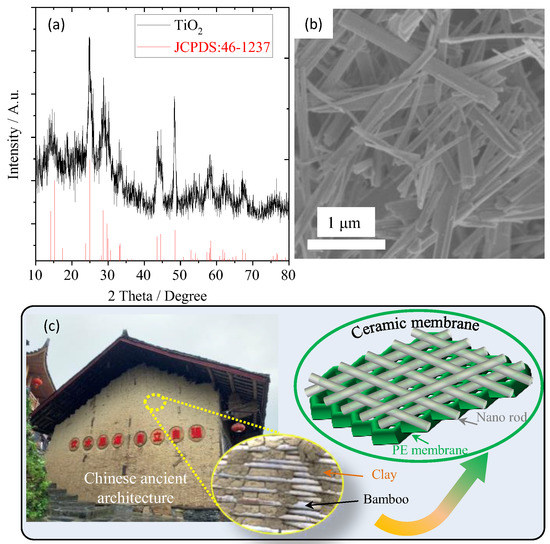
Figure 1.
(a) XRD pattern and (b) SEM image of the as-synthesized TiO2 nanorods, (c) is the schematic diagram for ceramic separator obtained from TiO2 nanorods.
The surface morphologies of the pristine PE separator and ceramic separators are shown in Figure 2. The pristine PE separator (Figure 2a) has a typical interconnected submicron pore structure originating from the wet method. This structure can facilitate the storage of electrolytes and allow the free migration of lithium ions inside the separator. Compared with the pristine separators, as depicted in Figure 2b,d–f, all the ceramic separators have similar surface morphologies for the inorganic coating layer, where the TiO2 nanorods are uniformly dispersed and interlaced on the surface of the PE separator, forming a three-dimensional network with porous structure. The surface morphology of the reverse side of the coating layer for the sample of C-0.6 was also examined, as shown in Figure 2c. It was found that the pore structures of the PE separator can be maintained after the coating process, indicating that the TiO2 nanorods, unlike other nanoparticles, did not clog the micropores because the nanorods with a high ratio of length to diameter tend to bridge over the micropores while the nanoparticles with a small size can be embedded into the micropores preventing the Li-ions from migrating through the separator. Besides, the morphologies of the cross-sectional and the thicknesses of the coating layer for the ceramic separators were observed with SEM and liner SEM methods, respectively, as shown in Figure 2g–j. The structures of the coating can be observed clearly, and the thickness for the samples of C-0.6, C-0.9, C-1.2, and C-1.5 are 0.5, 0.9, 1.3, and 2.1 μm, respectively. These results are consistent with the actual coating amount tested by weighing method, where the actual coating amount for sample C-0.6, C-0.9, C-1.2, and C-1.5 are 0.6, 0.97, 1.24, and 1.83 mg/cm2, respectively.
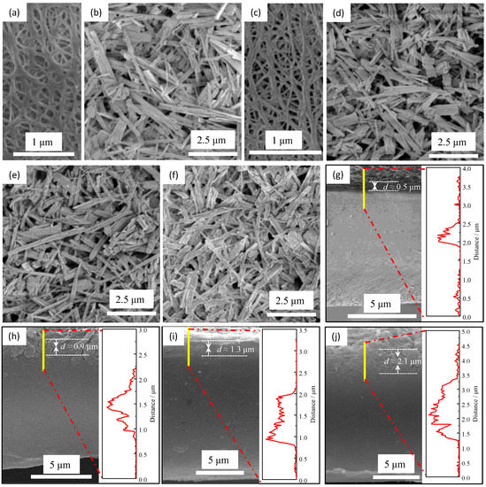
Figure 2.
The SEM images for the pristine PE separator (a) and the ceramic separators with different coating amounts (b–j): the surface morphologies for the coating layer (b) and the reverse side of the coating layer (c) of sample C-0.6. (d–f) are the surface morphologies for coating of samples C-0.9, C-1.2, and C-1.5, respectively. (g–j) are the cross-section morphologies and the thicknesses of the coating layer for the ceramic separators C-0.6, C-0.9, C-1.2, and C-1.5, respectively.
In order to investigate the thermal-resistant characteristics of the ceramic separators with different coating amounts, thermal shrinkage behaviors are observed by measuring the dimensional change (area-based) after storing the separators at 140 °C for 0.5 h. The results are shown in Figure 3a–g. It can be seen that the pristine PE separator (in Figure 3a) easily loses dimensional stability due to its low melting point of around 130 °C, which may cause an internal short circuit in the battery, further resulting in thermal runaway. When the synthesized TiO2 nanorods are used to modify the pristine PE separator, their thermal stability at high temperatures is significantly improved even under low coating amounts, as shown in Figure 3b. The thermal shrinkage of C-0.6 is about 4.5%, which is within the acceptable value (5%) for commercial cell [30,31,32]. When the coating amount increases, as shown in Figure 3c–e, their thermal shrinkage decreases gradually. The shrinkage of C-1.5 is almost negligible, while the coating amount increases to 1.83 mg/cm2. In addition, the morphology for the reverse side of the coating of sample C-0.6 after the thermal shrinkage test was also investigated by SEM measurement. Compared with the surface characteristics before the thermal shrinkage test (Figure 2a,c), most of the micropores can still maintain the original structure except for some micropores closed by melting in Figure 3f, indicating that the ultrathin coating layer composed of TiO2 nanorods can effectively inhibit the shrinkage of the pristine PE separator at high temperature. It is observed in Figure 3b–f that the optimum coating amount is about 0.6 mg/cm2 (C-0.6) because it will not introduce too much inert material and reduce the energy density of the battery while can obtain decent thermal shrinkage. In order to study the influence of different coating materials on the thermal stability of the separator, TiO2 nanoparticles with a diameter of about 50 nm were also used to modify the PE surface. The coating amount was tailored based on its thermal shrinkage, which is exactly equivalent to that of sample C-0.6, as depicted in Figure 3g,h. The coating thickness for C-P is about 4 μm which is much thicker than that of C-0.6 (0.5 μm, observed in Figure 2g). It unequivocally demonstrated that the coating material with nanorods compared with nanoparticles could not only effectively reduce the coating thickness and the use of inert substances, improve the energy density of batteries, but also effectively inhibit thermal shrinkage of the separator at high temperatures. Moreover, the differential scanning calorimeter (DSC) analysis was carried out to illustrate the effect of surface coating on the thermal stability of ceramic separators with different coating amounts. As shown in Figure 3i, the melting point of the pristine PE separator is 134.9 °C, which is consistent with previous literatures [33,34]. While the melting point of the ceramic separators was significantly improved after coating with TiO2 nanorods, a smaller increase was observed after the coating thickness increased to more than 1.3 μm (C-1.2 and C-1.5). Therefore, it can be concluded that the thermal stability for all the ceramic separators was greatly improved, but the optimum coating amount is about 0.6 mg/cm2 because when the coating amount is greater than this value, the introduction of massive non-electrochemical substances and the resulting reduction of the energy density will offset the slightly improved thermal stability of separators.
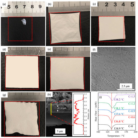
Figure 3.
Thermal shrinkage (%) of PE separator (a) and ceramic separators at 140 °C for 0.5 h: (b) C-0.6, (c) C-0.9, (d) C-1.2, (e) C-1.5 and (g) C-P. (f) is the SEM image for the reverse side of the coating of sample C-0.6 after thermal shrinkage test. (h) is the cross-section morphology and the thicknesses of the coating layer for C-0.6. (i) is the DSC curves for PE separators and ceramic separators.
The influence of coating amount on the mechanical properties of separators is analyzed by tension testing. As shown in Figure 4a, the tensile strength of the pristine separator (sample C-0) is 15.5 MPa, and it can be improved after coating with the synthesized TiO2 nanorods, as evidenced by the tensile strengths of 17.0 (C-0.6), 17.36 (C-0.9), 17.98 (C-1.2) and 18.05 (C-1.5) MPa, respectively, which is consistent with the aforementioned thermal stability analysis. Therefore, based on the analysis results of mechanical properties and thermal stability, a possible mechanism was proposed in Figure 4b. The coating can be divided into a surface layer and a stacking layer. Firstly, in the surface layer, some TiO2 nanorods “bridged” on the skeletons of the microporous of the pristine membrane through the binder. Then, the other TiO2 nanorods will stack on the surface layer to form a stacking layer, where these TiO2 nanorods do not interact directly with the pristine membrane. When the separator is subjected to external force (mechanical stretching or thermal shrinkage), the micropores can maintain the original shape and keep themselves from thermal shrinkage or mechanical stretching mainly due to the interaction between the skeletons of the microporous and TiO2 nanorods in the surface layer rather than the interaction between the skeletons of the microporous and TiO2 nanorods in stacking layer. Therefore, smaller improvements in thermal stability and mechanical strength were observed when the coating amount of TiO2 nanorods increased to above 0.6 mg/cm2. However, if the TiO2 nanoparticles are used to modify the pristine separator, the interaction between TiO2 nanoparticles and the skeleton of the pristine separator can only occur by “point” gluing rather than “bridging” gluing when the separator is subjected to external force (mechanical stretching or thermal shrinkage), this bonding mode is very inefficient in preventing the shrinkage or extension of the separator.
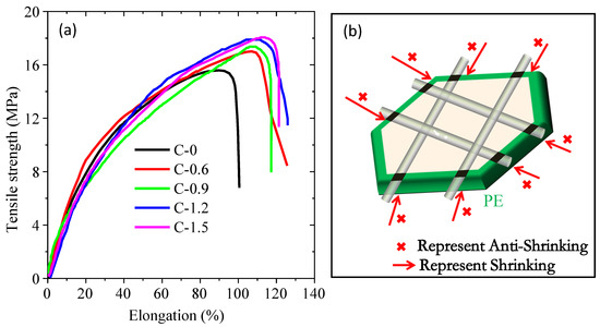
Figure 4.
The stress-strain curves of the ceramic separators with different coating amounts (a) and anti-shrinkage mechanism diagram (b).
The electrochemical performances of ceramic separators with different coating amounts were characterized by the electrochemical workstation. The electrochemical window is a vital parameter to evaluate the electrochemical stability of separators, which were usually investigated by linear sweep voltammetry (LSV) tests. Generally, the onset of the suddenly increasing current was caused by the oxidative reaction of electrolyte decomposition, and the corresponding voltage indicates the maximum electrochemical stable voltage [35,36]. As shown in Figure 5a, there were no obvious current changes during the potential sweeps at 4 V, whereas the current showed a dramatic difference between 4.0 and 5.5 V. The electrochemical stabilities of PE separators are about 4.1 V (vs. Li+/Li). In comparison, the current onsets of C-0.6, C-0.9, C-1.2, and C-1.5 separators are 5.3 V. The TiO2 nanorods-coated separator has a wider electrochemical stability window, which indicates that the TiO2 nanorod-modified separator possesses better electrochemical stability. The stability enhancement means better compatibility with the electrolyte of the lithium-ion battery, which should be attributed to the excellent electrolyte affinity of TiO2-coated PE separator and the stabilization of electrolyte anions by Ti-O units acting as the Lewis acid centers [37,38,39]. Ionic conductivity is another important indicator to evaluate the electrochemical performance of the separator. Figure 5b shows the Nyquist plots of the stainless steel (SS)/separator-electrolyte/SS molds assembled by sandwiching the pristine PE separator or coated separators soaking in liquid electrolyte between two pieces of SS. The high-frequency intercept on the real axis reflects the bulk resistance (Rb), which can be used to calculate the ionic conductivity in Table 1. According to the results, all TiO2 nanorod-modified PE separators show higher ionic conductivity than the pristine PE separator, and the highest ionic conductivity was observed for sample C-0.6, which may benefit from the synergistic contributions of the significantly increased electrolyte uptake and the well-preserved porous structure [13,40], as observed in Figure 2c. The compatibility of liquid electrolyte-soaked separators with a lithium electrode is also a very important factor in the C-rate capability of lithium-ion batteries, which can be investigated by evaluating the impedance variation of Li/liquid electrolyte-soaked separator/Li cells. As shown in Figure 5c, a semicircle was observed from the impedance spectra of cells with all separators that represent the Li/electrolyte interfacial resistance (Rint), which was related to the charge transport across the passivation layer (solid electrolyte film) and the charge transfer reaction, Li+ + e− = Li [3,37]. The Rint for C-0, C-0.6, C-0.9, C-1.2, and C-1.5 samples are 243 Ω, 118 Ω, 124 Ω, 141 Ω and 161 Ω, respectively. Compared with the uncoated PE separator, it can be seen that all TiO2 nanorod-modified PE separators had lower interfacial resistance, indicating smooth ion transport between the ceramic nanoparticle-coated separators and electrodes. It can be attributed to the TiO2 nanorod-modified PE separators capable of retaining the original porous structure and the layer of TiO2 nanorods able to obtain higher electrolyte uptake (Table 1), which can effectively decrease the interaction between electrolyte components and the lithium electrode, and gradually stabilizes the interface [41]. Moreover, the C-0.6 separator exhibited the smallest interfacial impedance and therefore had the best separator-electrode compatibility. This is consistent with previous research [38,42] that a very thin inorganic oxide layer can negate the interfacial impedance between the electrolyte and lithium metal, owing to the high binding energy between lithium and the oxides layer.
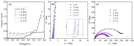
Figure 5.
The Linear scan voltammetry (LSV) curve of Li/separator- liquid electrolyte/SS cells (a), AC impedance spectra of the SS/separator-liquid electrolyte/SS cell (b), the interfacial resistances of the Li/separator-liquid electrolyte/Li cell (c).

Table 1.
Properties of the surface-modified separators.
From the results of thermal stability, mechanical properties, and electrochemical performance tests for TiO2 nanorod-modified separators with different coating amounts, sample C-0.6 has the best overall performance, such as the best ionic conductivity and interfacial impedance, excellent electrochemical stability window, acceptable thermal stability and mechanical properties, the minimum introduction of inert ingredients. Therefore, the electrochemical performance of the half-cell composed of the sample C-0.6 separator, a negative electrode (lithium metal), and a positive electrode (LiCoO2) was further studied. For better comparative analysis, the electrochemical performance of the half-cell assembled by pristine PE membrane (C-0) was also tested. As shown in Figure 6a, the discharge specific capacity at low rates and its capacity recovering property (0.2 C) after 7 C for C-0.6 and C-0 are very close, but their differences gradually become larger with the increase of discharge current density. When the discharge current density is 7 C, the specific capacities of C-0.6 and C-0 are ~86.4 and ~60.4 mAh g−1, respectively. Moreover, from their discharge curve in Figure 6b,c, it can be further seen that there is little difference in the curve shape and the average discharge voltage platform under low rates, while the voltage platform decrease for the C-0 sample is more than that of C-0.6 at high rates. These results indicate that the polarization resistance of the battery assembled by TiO2 nanorod-modified separator is smaller than that of the battery composed of the pristine separator at high rates, which is consistent with the test results of ionic conductivity (Figure 5b), interfacial impedance (Figure 5c) and electrolyte uptake (Table 1). Furthermore, the cycle performance of these half-cells was studied, as depicted in Figure 6d. At the discharge current density of 0.5 C, the capacity retention of the C-0.6 sample is 82.6% after 100 cycles, while that of the C-0 sample is only 77.8%. Similarly, from their representative discharge curves (Figure 6e,f), it can be seen that the C-0.6 sample can maintain a good discharge capacity after cycling.
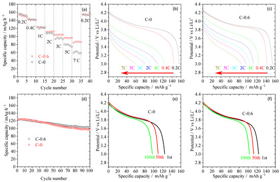
Figure 6.
The C-rate capabilities (a) and their corresponding discharge profiles (b,c) of half-cells assembled with pristine PE separator (C-0 sample) and TiO2 nanorod-modified PE separator (C-0.6 sample), where charge/discharge current densities are varied from 0.2/0.2–7/7 C under a voltage range between 3.0 and 4.2 V. the cyclic performance at 0.5 C (d) and their corresponding discharge profiles (e,f) of half-cells assembled with pristine PE separator (C-0 sample) and TiO2 nanorod-modified PE separator.
In order to further understand the influence of the TiO2 nanorod-modified layer on the electrochemical performance of the PE separator, AC impedance spectrum analysis was performed on the half-cell assembled by the C-0.6 and C-0 separators. As can be seen from the Nyquist plot in Figure 7, the semicircle in the high-middle frequency region represents the interfacial resistance (Rint) modified by the combined effect of solid-electrolyte interface resistance (RSEI) and charge-transfer resistance (Rct). The TiO2 nanorod-modified PE separator (C-0.6) exhibited a smaller semicircle at high-middle frequency, indicating that their interfacial resistance is relatively low compared with that of the pristine PE separator. These results were ascribed to surface modification leading to enhanced hydrophilicity and affinity with electrolyte, resulting in thinner and more compact SEI formation by TiO2 nanorod-modified PE separator, which agreed with the findings of the ionic conductivity (Figure 5b), interfacial resistance (Figure 5c) and electrolyte uptake (Table 1).
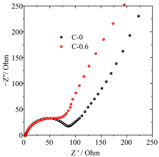
Figure 7.
Nyquist plots of half-cells assembled with pristine PE (C-0) and TiO2 nanorod-modified PE (C-0.6) separator.
4. Conclusions
In this paper, the TiO2 nanorods with a diameter of about 10–100 nanometers and a length of about tens of microns are used to modify the PE separator. It can be observed from SEM tests that the TiO2 nanorods are “bridged” on the microporous skeleton of pristine PE separator to form a coating structure with a three-dimensional porous network, while the TiO2 nanoparticles are “embedded” into the micropores, which will cause a series of problems such as micropore blockage, easy detaching, and introduction of excessive inert substances. Then, multiple analytical techniques (e.g., SEM, DSC, EIS, LSV, and so on.) are also utilized to investigate the effect of coating amount on the physicochemical and electrochemical properties of ceramic separator. The results showed that these properties can be effectively improved by coating TiO2 nanorods, but the degree of improvement is not directly proportional to the coating amount. For example, the thermal stability and mechanical properties of the ceramic separator increase with the increase of the coating amount, however, smaller improvements are observed when the coating amount is above 0.6 mg/cm2. In fact, when the separator is subjected to external force (mechanical stretching or thermal contraction), the forces inhibiting micropore deformation are derived from the interaction of TiO2 nanorods directly “bridging” with the microporous skeleton rather than those indirectly “glued” with the microporous skeleton. In addition, when the loading level is 0.6 mg/cm2, the ceramic separator can achieve optimal performance in terms of ionic conductivity, electrochemical stability window, and interface compatibility because the introduction of excessive inert coating material can reduce the ionic conductivity, increase the interfacial impedance, and lower the energy density of the battery. Moreover, the capacity retention assembled by the ceramic separator with a loading of 0.6 mg/cm2 TiO2 nanorods was 57.1% under 7 C/0.2 C and 82.6% after 100 cycles, respectively, indicating that the ceramic separator with a thin coating layer has well-balanced performances. This research may provide a novel approach to overcoming the common disadvantages of current surface-coated separators.
Author Contributions
Conceptualization, Z.C. and X.Y.; Methodology, T.W.; Validation, Y.P.; Investigation, C.H.; Data curation, H.Z.; Writing—original draft, Z.C. All authors have read and agreed to the published version of the manuscript.
Funding
Z. Chen wants to acknowledge the financial support from the Natural Science Foundation of Hunan Province of China (No. 2021JJ30374), Hunan Provincial Education Office Foundation of China (No. 19A261), and Key R & D projects in Hunan Province (No. 2021GK2015). T. Wang wants to acknowledge the financial support from Natural Science Foundation of Guangdong Province of China‐Regional joint fund (No. 2021B1515140025) and Natural Science Foundation of Guangdong Province of China‐General Program (No. 2022A1515010972).
Data Availability Statement
Not applicable.
Conflicts of Interest
The authors declare no conflict of interest.
References
- Liu, K.; Liu, Y.; Lin, D.; Pei, A.; Cui, Y. Materials for lithium-ion battery safety. Sci. Adv. 2018, 4, eaas9820. [Google Scholar] [CrossRef] [PubMed]
- Lagadec, M.F.; Zahn, R.; Wood, V. Characterization and performance evaluation of lithium-ion battery separators. Nat. Energy 2018, 4, 16–25. [Google Scholar] [CrossRef]
- Jana, K.K.; Lue, S.J.; Huang, A.; Soesanto, J.F.; Tung, K.-L. Separator Membranes for High Energy-Density Batteries. ChemBioEng Rev. 2018, 5, 346–371. [Google Scholar] [CrossRef]
- Feng, X.; Ouyang, M.; Liu, X.; Lu, L.; Xia, Y.; He, X. Thermal runaway mechanism of lithium ion battery for electric vehicles: A review. Energy Storage Mater. 2018, 10, 246–267. [Google Scholar] [CrossRef]
- Lu, W.; Yuan, Z.; Zhao, Y.; Zhang, H.; Zhang, H.; Li, X. Porous Membranes in Secondary Battery Technologies. Chem. Soc. Rev. 2017, 46, 2199–2236. [Google Scholar] [CrossRef]
- Wang, W.; Liao, C.; Liew, K.M.; Chen, Z.; Song, L.; Kan, Y.; Hu, Y. A 3D flexible and robust HAPs/PVA separator prepared by a freezing-drying method for safe lithium metal batteries. J. Mater. Chem. A 2019, 7, 6859–6868. [Google Scholar] [CrossRef]
- Chen, R.; Qu, W.; Guo, X.; Li, L.; Wu, F. The pursuit of solid-state electrolytes for lithium batteries: From comprehensive insight to emerging horizons. Mater. Horiz. 2016, 3, 487–516. [Google Scholar] [CrossRef]
- Jeong, K.; Park, S.; Lee, S.-Y. Revisiting polymeric single lithium-ion conductors as an organic route for all-solid-state lithium ion and metal batteries. J. Mater. Chem. A 2019, 7, 1917–1935. [Google Scholar] [CrossRef]
- Fan, L.; Wei, S.; Li, S.; Li, Q.; Lu, Y. Recent Progress of the Solid-State Electrolytes for High-Energy Metal-Based Batteries. Adv. Energy Mater. 2018, 8, 1702657. [Google Scholar] [CrossRef]
- Na, W.; Koh, K.H.; Lee, A.S.; Cho, S.; Ok, B.; Hwang, S.-W.; Lee, J.H.; Koo, C.M. Binder-less chemical grafting of SiO2 nanoparticles onto polyethylene separators for lithium-ion batteries. J. Membr. Sci. 2019, 573, 621–627. [Google Scholar] [CrossRef]
- Liao, H.; Zhang, H.; Qin, G.; Hong, H.; Li, Z.; Lin, Y.; Li, L. Novel Core-Shell PS-co-PBA@SiO2 Nanoparticles Coated on PP Separator as “Thermal Shutdown Switch” for High Safety Lithium-Ion Batteries. Macromol. Mater. Eng. 2017, 302, 1700241. [Google Scholar] [CrossRef]
- Liao, C.; Wang, W.; Han, L.; Mu, X.; Wu, N.; Wang, J.; Gui, Z.; Hu, Y.; Kan, Y.; Song, L. A flame retardant sandwiched separator coated with ammonium polyphosphate wrapped by SiO2 on commercial polyolefin for high performance safety lithium metal batteries. Appl. Mater. Today 2020, 21, 100793. [Google Scholar] [CrossRef]
- Wang, Q.; Yang, J.; Wang, Z.; Shi, L.; Zhao, Y.; Yuan, S. Dual-Scale Al2O3 Particles Coating for High-Performance Separator and Lithium Metal Anode. Energy Technol. 2020, 8, 1901429. [Google Scholar] [CrossRef]
- Qiu, Z.; Yuan, S.; Wang, Z.; Shi, L.; Jo, J.H.; Myung, S.-T.; Zhu, J. Construction of silica-oxygen-borate hybrid networks on Al2O3-coated polyethylene separators realizing multifunction for high-performance lithium ion batteries. J. Power Source 2020, 472, 228445. [Google Scholar] [CrossRef]
- Yeon, D.; Lee, Y.; Ryou, M.H.; Lee, Y.M. New flame-retardant composite separators based on metal hydroxides for lithium-ion batteries. Electrochim. Acta 2015, 157, 282–289. [Google Scholar] [CrossRef]
- Cui, J.; Liu, J.; He, C.; Li, J.; Wu, X. Composite of polyvinylidene fluoride-cellulose acetate with Al(OH)3 as a separator for high-performance lithium ion battery. J. Membr. Sci. 2017, 541, 661–667. [Google Scholar] [CrossRef]
- Shekarian, E.; Nasr, M.R.J.; Mohammadi, T.; Bakhtiari, O.; Javanbakht, M. Preparation of 4A zeolite coated polypropylene membrane for lithium-ion batteries separator. J. Appl. Polym. Sci. 2019, 136, 47841. [Google Scholar] [CrossRef]
- Dong, X.; Mi, W.; Yu, L.; Jin, Y.; Lin, Y.S. Zeolite coated polypropylene separators with tunable surface properties for lithium-ion batteries. Microporous Mesoporous Mater. 2016, 226, 406–414. [Google Scholar] [CrossRef]
- Liu, L.; Wang, Y.; Gao, C.; Yang, C.; Wang, K.; Li, H.; Gu, H. Ultrathin ZrO2-coated separators based on surface sol-gel process for advanced lithium ion batteries. J. Membr. Sci. 2019, 592, 117368. [Google Scholar] [CrossRef]
- Kim, K.J.; Kwon, H.K.; Park, M.S.; Yim, T.; Yu, J.S.; Kim, Y.J. Ceramic composite separators coated with moisturized ZrO2 nanoparticles for improving the electrochemical performance and thermal stability of lithium ion batteries. Phys. Chem. Chem. Phys. 2014, 16, 9337–9343. [Google Scholar] [CrossRef]
- Peng, K.; Wang, B.; Li, Y.; Ji, C. Magnetron sputtering deposition of TiO2 particles on polypropylene separators for lithium-ion batteries. RSC Adv. 2015, 5, 81468–81473. [Google Scholar] [CrossRef]
- Kim, P.S.; Le Mong, A.; Kim, D. Thermal, mechanical, and electrochemical stability enhancement of Al2O3 coated polypropylene/polyethylene/polypropylene separator via poly(vinylidene fluoride)-poly(ethoxylated pentaerythritol tetraacrylate) semi-interpenetrating network binder. J. Membr. Sci. 2020, 612, 118481. [Google Scholar] [CrossRef]
- Zhu, X.; Jiang, X.; Ai, X.; Yang, H.; Cao, Y. A Highly Thermostable Ceramic-Grafted Microporous Polyethylene Separator for Safer Lithium-Ion Batteries. ACS Appl. Mater. Interfaces 2015, 7, 24119–24126. [Google Scholar] [CrossRef] [PubMed]
- Kim, J.Y.; Lim, D.Y. Surface-Modified Membrane as A Separator for Lithium-Ion Polymer Battery. Energies 2010, 3, 866–885. [Google Scholar] [CrossRef]
- Wang, W.; Yuen, A.C.Y.; Yuan, Y.; Liao, C.; Li, A.; Kabir, I.I.; Kan, Y.; Hu, Y.; Yeoh, G.H. Nano architectured halloysite nanotubes enable advanced composite separator for safe lithium metal batteries. Chem. Eng. J. 2023, 451, 138496. [Google Scholar] [CrossRef]
- Wang, X.; Peng, L.; Hua, H.; Liu, Y.; Zhang, P.; Zhao, J. Magnesium borate fiber coating separators with high Li-ion transference number for lithium ion batteries. ChemElectroChem 2020, 7, 1187–1192. [Google Scholar] [CrossRef]
- Hu, S.; Lin, S.; Tu, Y.; Hu, J.; Wu, Y.; Liu, G.; Li, F.; Yu, F.; Jiang, T. Novel aramid nanofiber-coated polypropylene separators for lithium ion batteries. J. Mater. Chem. A 2016, 4, 3513–3526. [Google Scholar] [CrossRef]
- Han, D.-H.; Zhang, M.; Lu, P.-X.; Wan, Y.-L.; Chen, Q.-L.; Niu, H.-Y.; Yu, Z.-W. A multifunctional separator with Mg(OH)2 nanoflake coatings for safe lithium-metal batteries. J. Energy Chem. 2021, 52, 75–83. [Google Scholar] [CrossRef]
- Deng, Q.; Wei, M.; Ding, X.; Jiang, L.; Wei, K.; Zhou, H. Large single-crystal anatase TiO2 Bipyramids. J. Cryst. Growth 2010, 312, 213–219. [Google Scholar] [CrossRef]
- Arora, P.; Zhang, Z. Battery Separators. Chem. Rev. 2004, 104, 4419–4462. [Google Scholar] [CrossRef]
- Heimes, H.H.; Kampker, A.; Lienemann, C.; Locke, M.; Offermanns, C. Lithium-Ion Battery Cell Production Process, 3rd ed.; PEM of RWTH Aachen and VDMA: Frankfurt am Main, Germany, 2019. [Google Scholar]
- Liu, Y.; Zhang, R.; Wang, J.; Wang, Y. Current and future lithium-ion battery manufacturing. iScience 2021, 24, 102332. [Google Scholar] [CrossRef] [PubMed]
- Gao, X.; Sheng, W.; Wang, Y.; Lin, Y.; Luo, Y.; Li, B.-G. Polyethylene battery separator with auto-shutdown ability, thermal stability of 220 °C, and hydrophilic surface via solid-state ultraviolet irradiation. J. Appl. Polym. Sci. 2015, 132, 42169. [Google Scholar] [CrossRef]
- Peng, L.; Kong, X.; Li, H.; Wang, X.; Shi, C.; Hu, T.; Liu, Y.; Zhang, P.; Zhao, J. A Rational Design for a High-Safety Lithium-Ion Battery Assembled with a Heatproof–Fireproof Bifunctional Separator. Adv. Funct. Mater. 2020, 31, 2008537. [Google Scholar] [CrossRef]
- Chen, W.; Shi, L.; Zhou, H.; Zhu, J.; Wang, Z.; Mao, X.; Chi, M.; Sun, L.; Yuan, S. Water-Based Organic-Inorganic Hybrid Coating for a High-Performance Separator. ACS Sustain. Chem. Eng. 2016, 4, 3794–3802. [Google Scholar] [CrossRef]
- Huang, F.; Xu, Y.; Peng, B.; Su, Y.; Jiang, F.; Hsieh, Y.-L.; Wei, Q. Coaxial Electrospun Cellulose-Core Fluoropolymer-Shell Fibrous Membrane from Recycled Cigarette Filter as Separator for High Performance Lithium-Ion Battery. ACS Sustain. Chem. Eng. 2015, 3, 932–940. [Google Scholar] [CrossRef]
- Wang, Z.; Guo, F.; Chen, C.; Shi, L.; Yuan, S.; Sun, L.; Zhu, J. Self-assembly of PEI/SiO2 on polyethylene separators for Li-ion batteries with enhanced rate capability. ACS Appl. Mater. Interfaces 2015, 7, 3314–3322. [Google Scholar] [CrossRef]
- Wu, S.; Ning, J.; Jiang, F.; Shi, J.; Huang, F. Ceramic Nanoparticle-Decorated Melt-Electrospun PVDF Nanofiber Membrane with Enhanced Performance as a Lithium-Ion Battery Separator. ACS Omega 2019, 4, 16309–16317. [Google Scholar] [CrossRef]
- Tan, L.; Li, Z.; Shi, R.; Quan, F.; Wang, B.; Ma, X.; Ji, Q.; Tian, X.; Xia, Y. Preparation and Properties of an Alginate-Based Fiber Separator for Lithium-Ion Batteries. ACS Appl. Mater. Interfaces 2020, 12, 38175–38182. [Google Scholar] [CrossRef]
- Rahman, M.M.; Mateti, S.; Cai, Q.; Sultana, I.; Fan, Y.; Wang, X.; Hou, C.; Chen, Y. High temperature and high rate lithium-ion batteries with boron nitride nanotubes coated polypropylene separators. Energy Storage Mater. 2019, 19, 352–359. [Google Scholar] [CrossRef]
- Wei, Z.; Gu, J.; Zhang, F.; Pan, Z.; Zhao, Y. Core-Shell Structured Nanofibers for Lithium Ion Battery Separator with Wide Shutdown Temperature Window and Stable Electrochemical Performance. ACS Appl. Polym. Mater. 2020, 2, 1989–1996. [Google Scholar] [CrossRef]
- Han, X.; Gong, Y.; Fu, K.K.; He, X.; Hitz, G.T.; Dai, J.; Pearse, A.; Liu, B.; Wang, H.; Rubloff, G.; et al. Negating interfacial impedance in garnet-based solid-state Li metal batteries. Nat. Mater. 2017, 16, 572–579. [Google Scholar] [CrossRef] [PubMed]
Disclaimer/Publisher’s Note: The statements, opinions and data contained in all publications are solely those of the individual author(s) and contributor(s) and not of MDPI and/or the editor(s). MDPI and/or the editor(s) disclaim responsibility for any injury to people or property resulting from any ideas, methods, instructions or products referred to in the content. |
© 2023 by the authors. Licensee MDPI, Basel, Switzerland. This article is an open access article distributed under the terms and conditions of the Creative Commons Attribution (CC BY) license (https://creativecommons.org/licenses/by/4.0/).