
Modeling of Interfacial Tension and Inclusion Motion Behavior in Steelmaking Continuous Casting Mold

 , , and
Abstract
1. Introduction
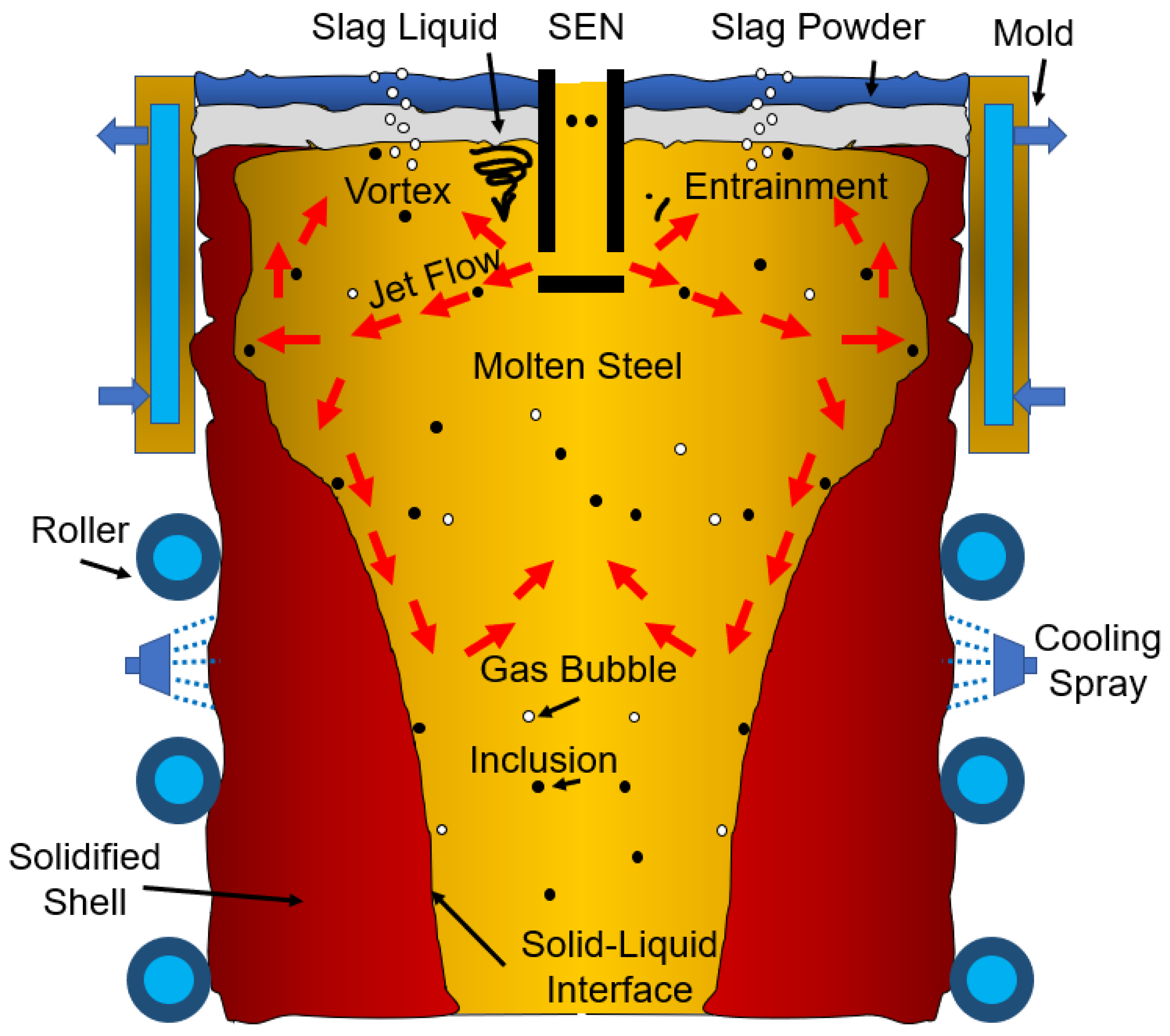
1.1. Impurities in Steel
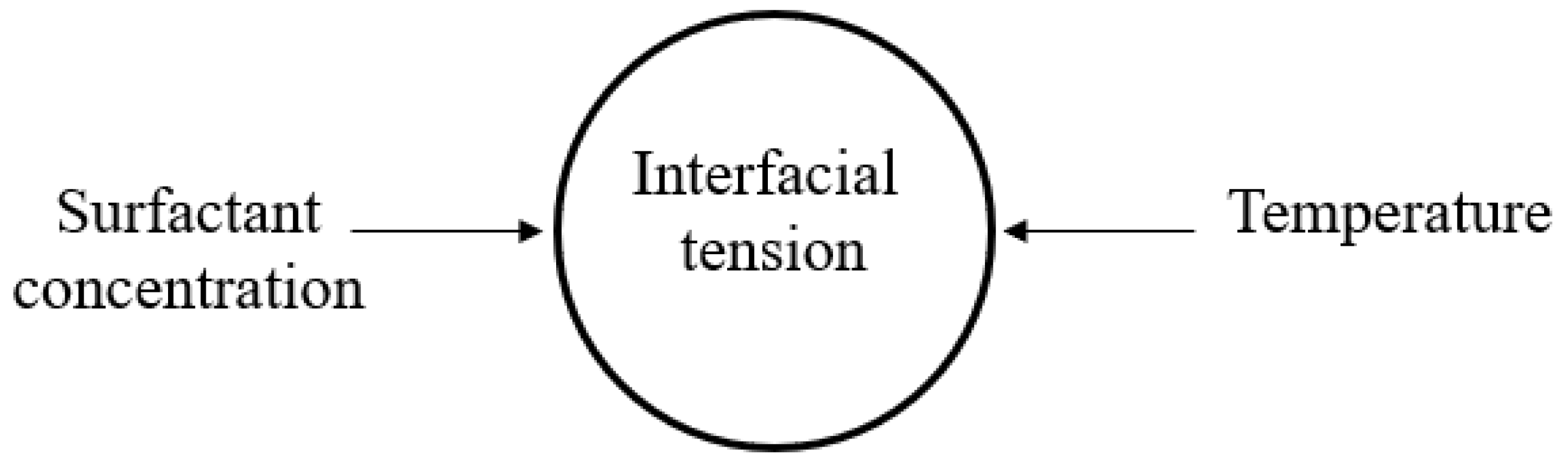
1.2. Effect of Interfacial Tension
2. Mathematical Modeling
2.1. The Governing Equation
- : stress tensor;
- p: static pressure;
- : external body force;
- : gravitational body force;
- Sm: mass source term.
- I: unit tensor;
- μ: molecular viscosity;
- : the result of volume dilation.
- : diffusion flux of species j;
- Sh is a volumetric heat source term;
- keff: effective conductivity (k + kt, where kt is the turbulent thermal conductivity, defined according to the turbulence model being used).
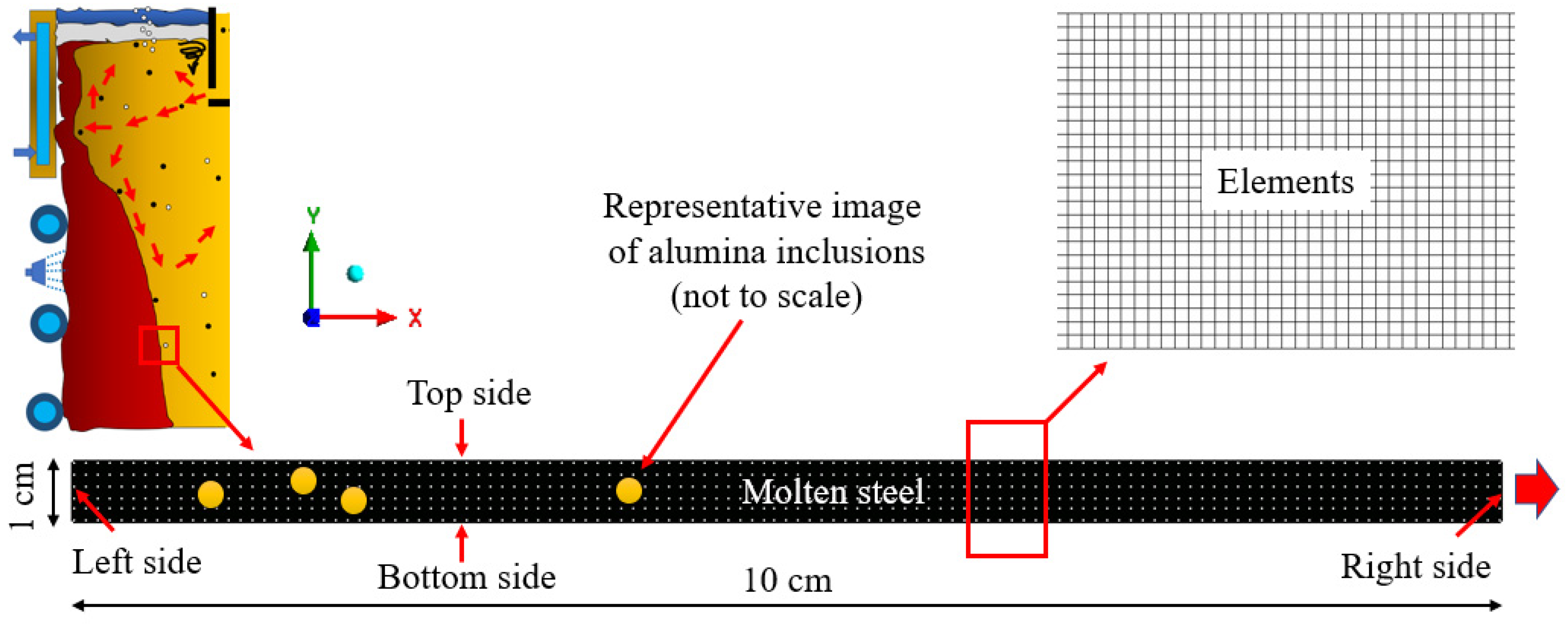
2.2. Computational Details
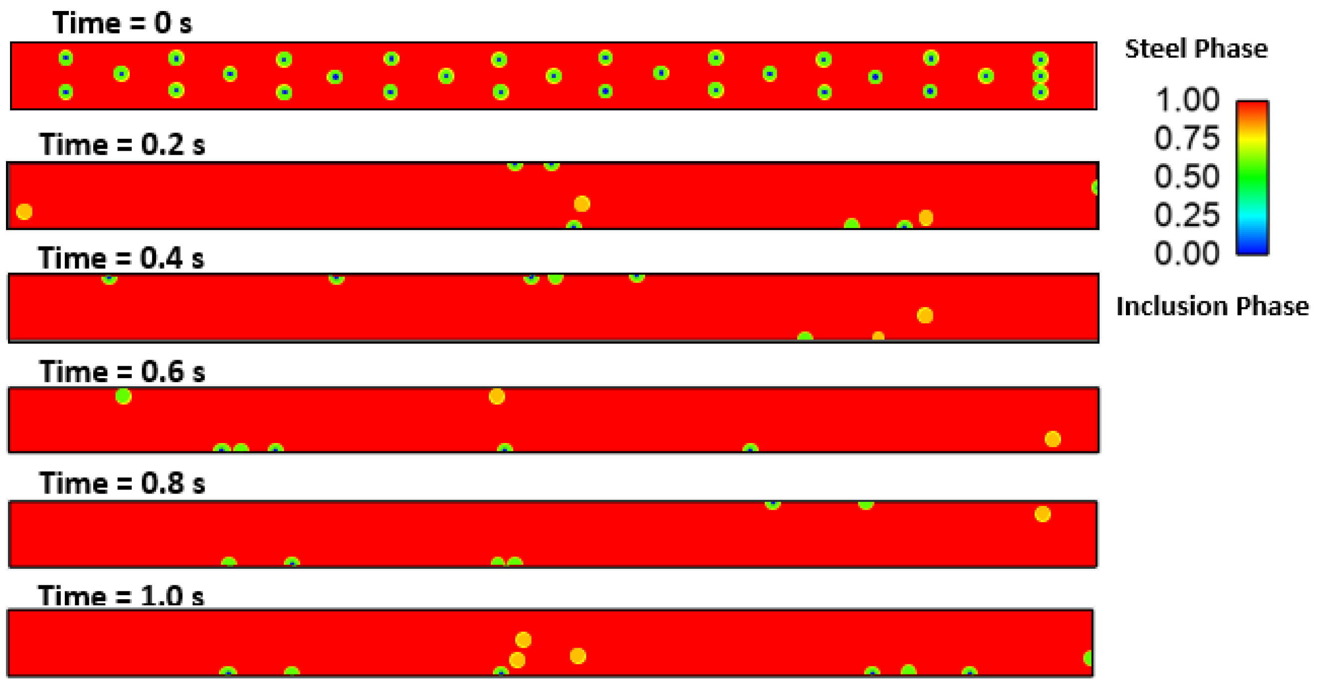
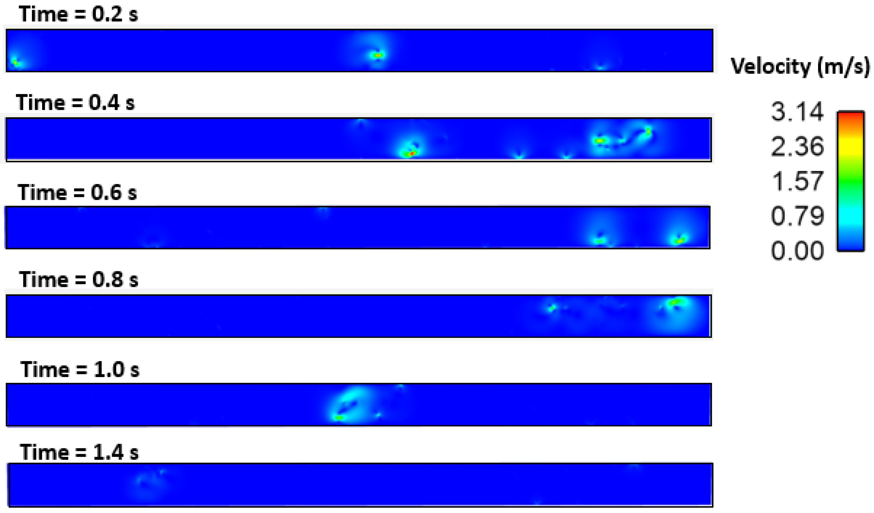
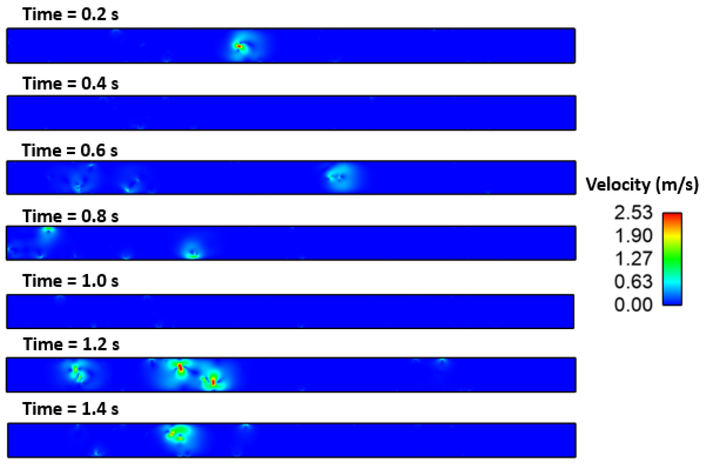
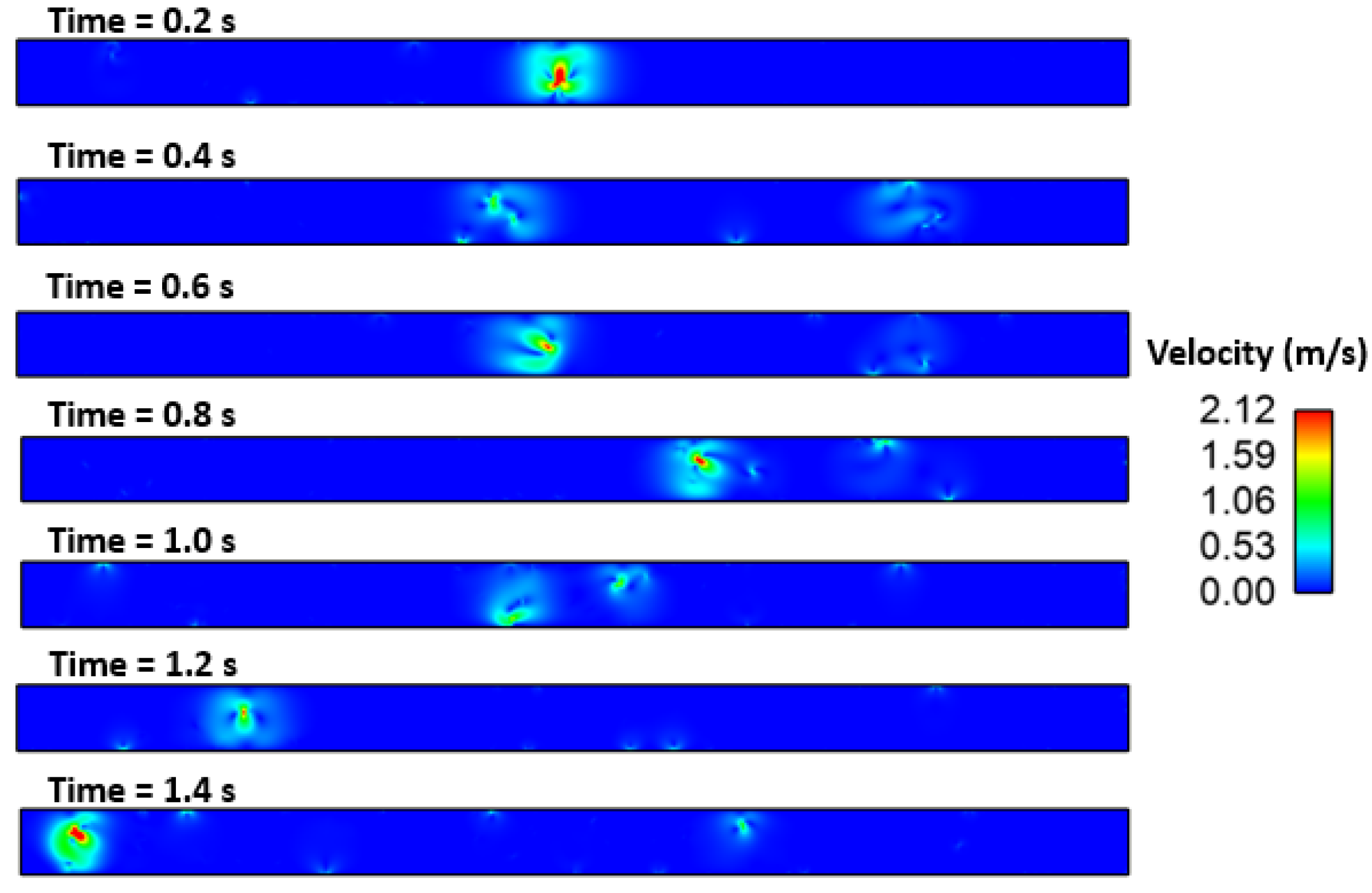
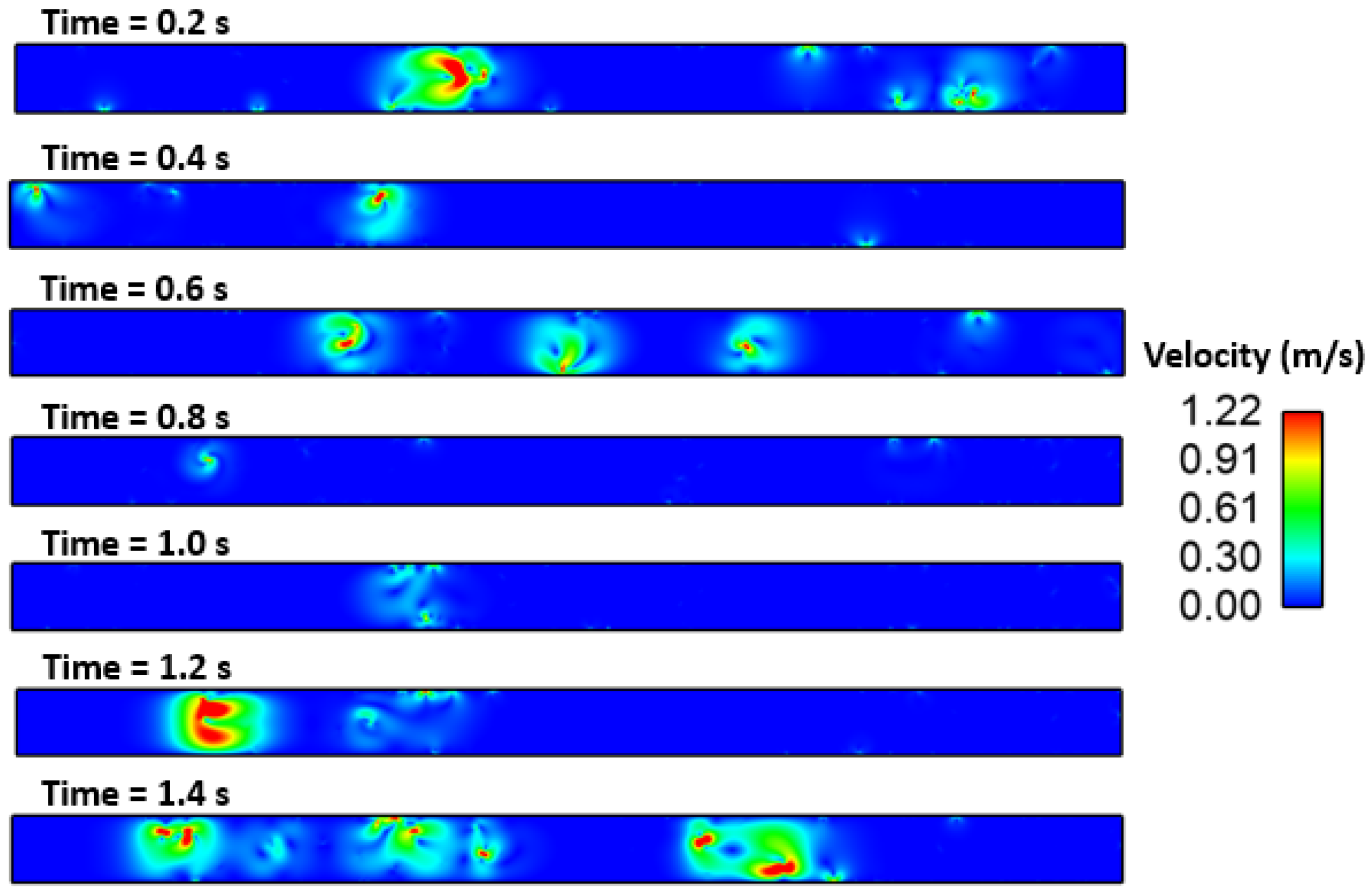
3. Results and Discussion
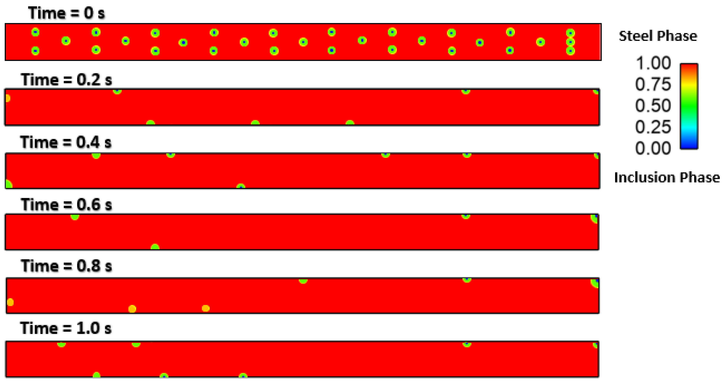
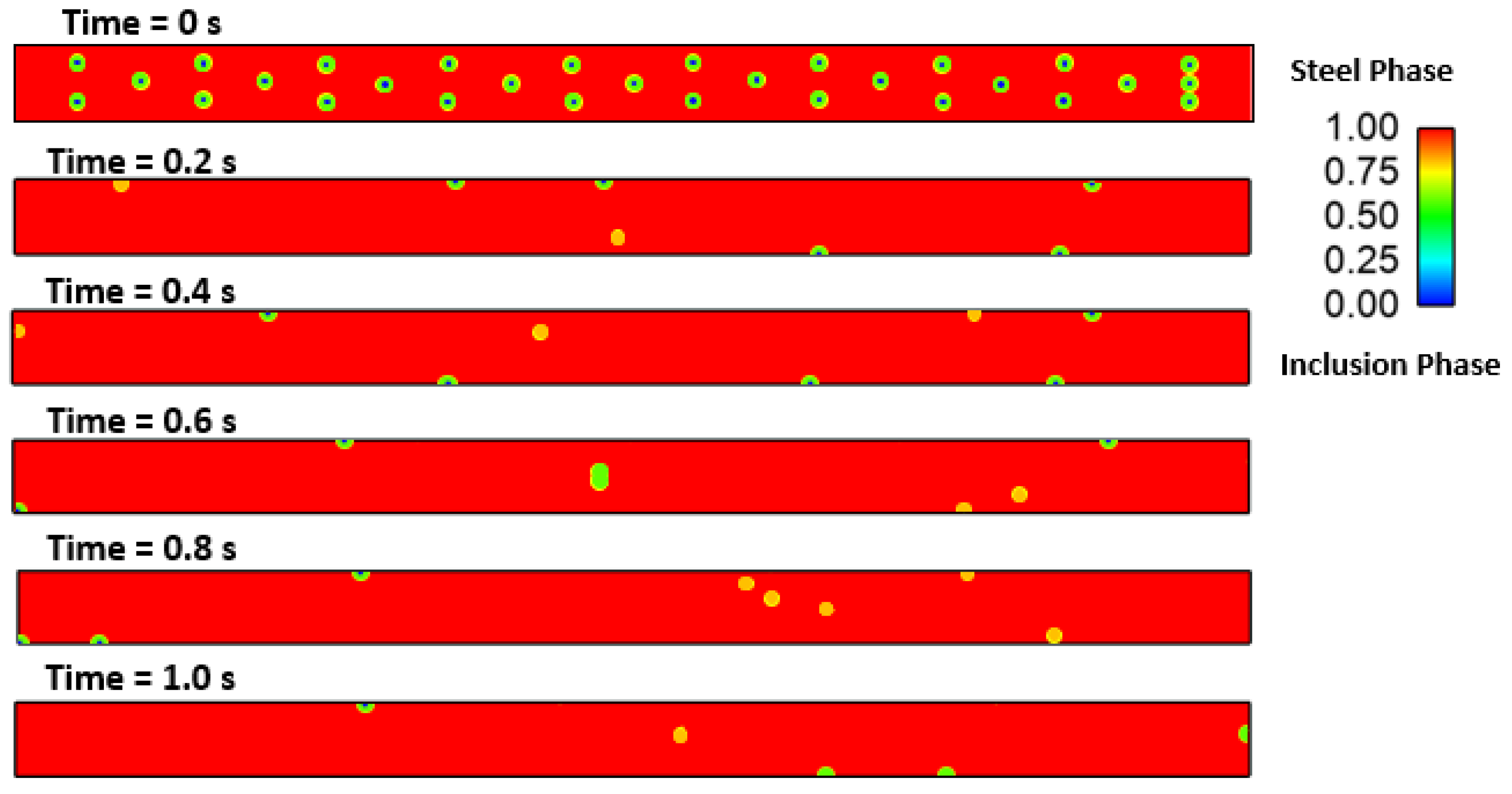
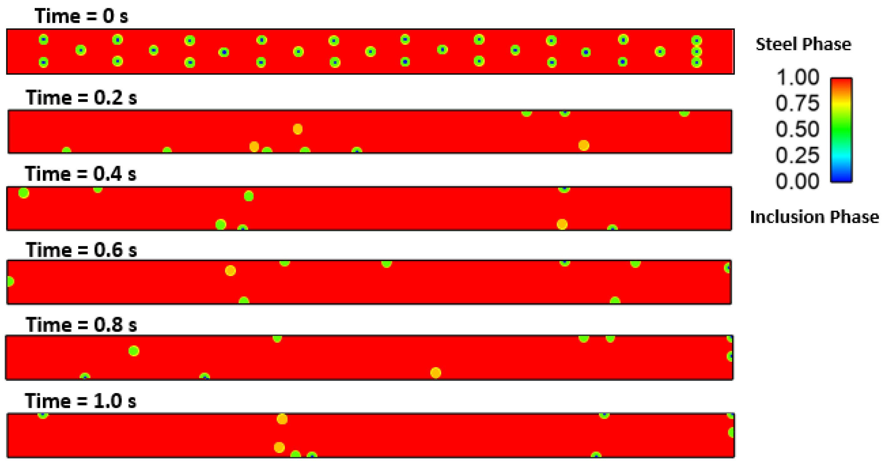
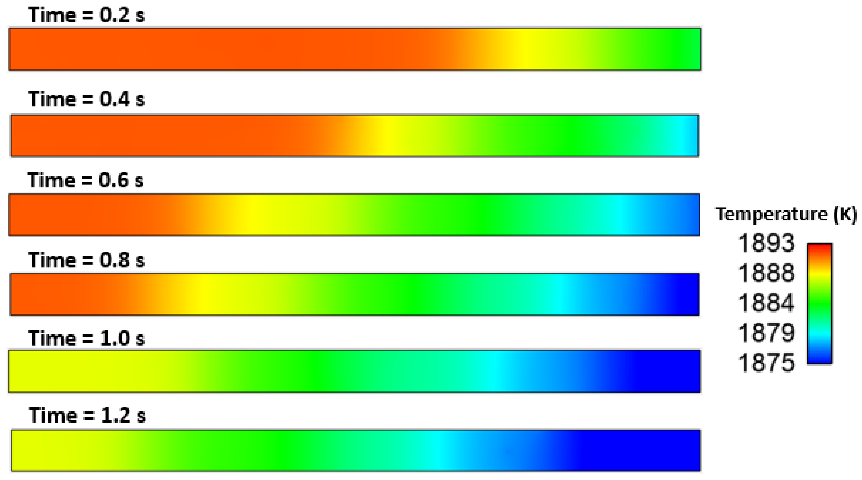
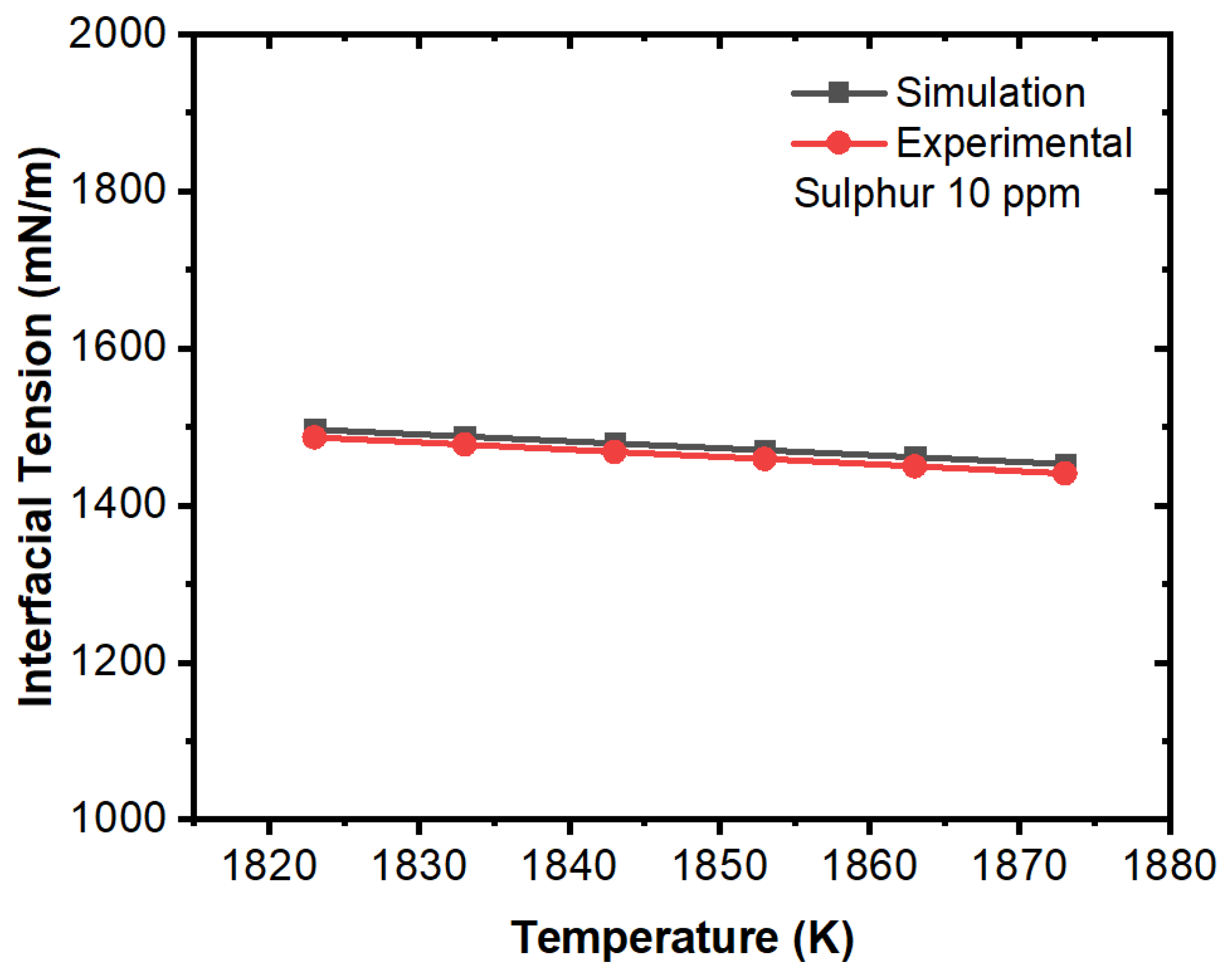
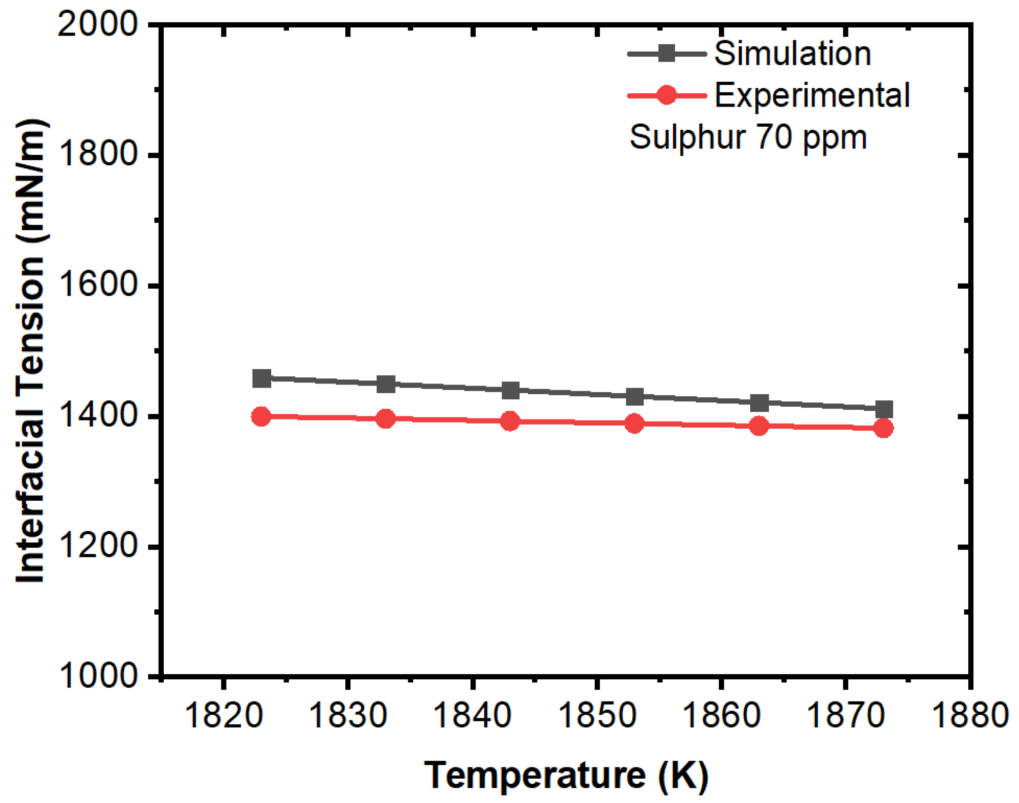
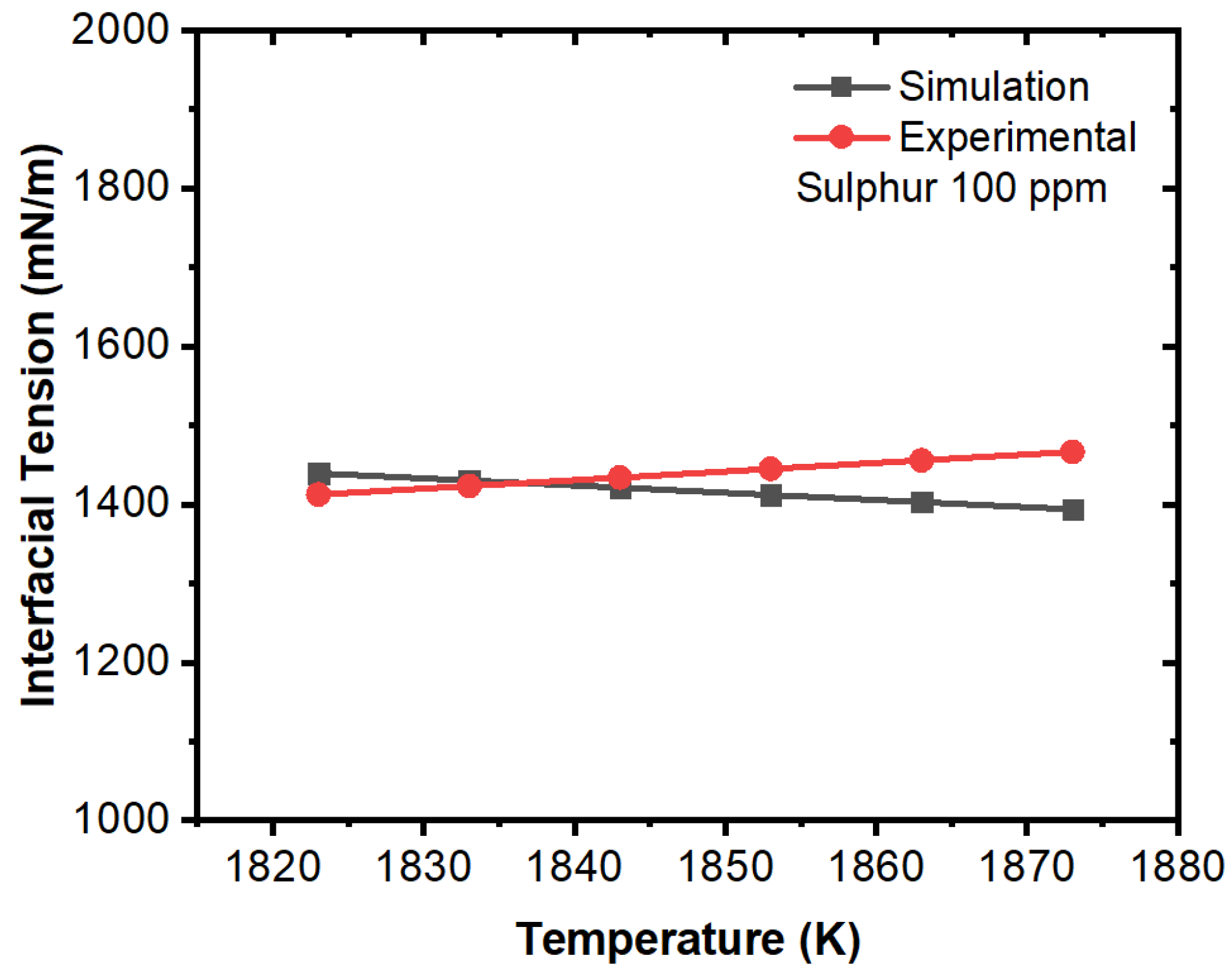
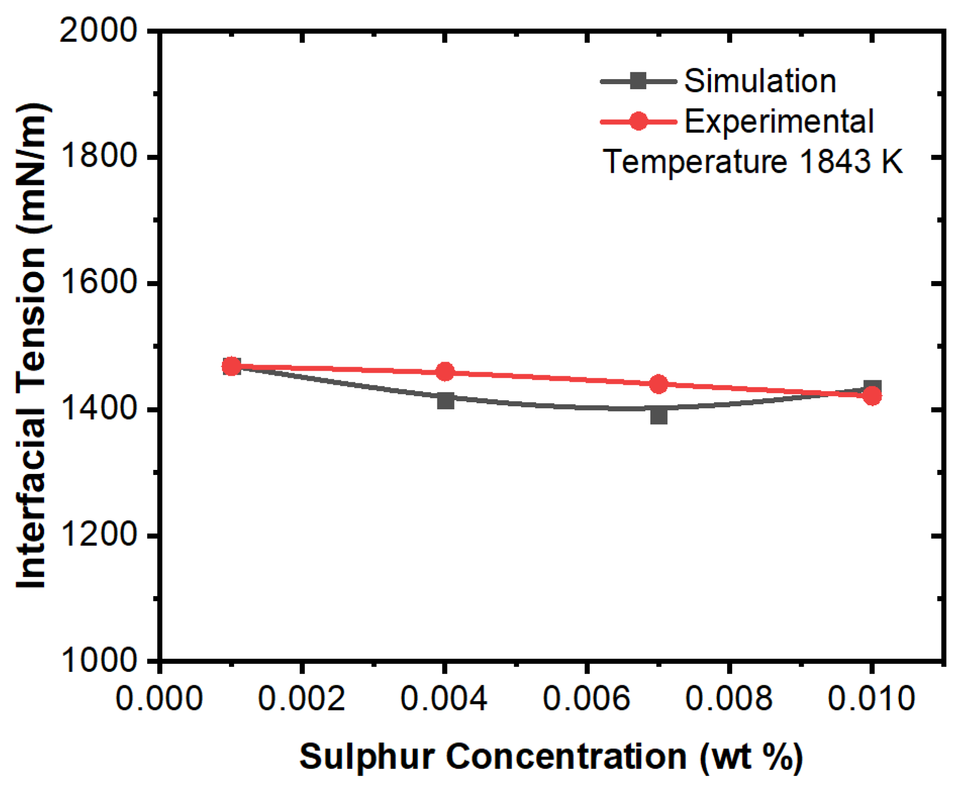
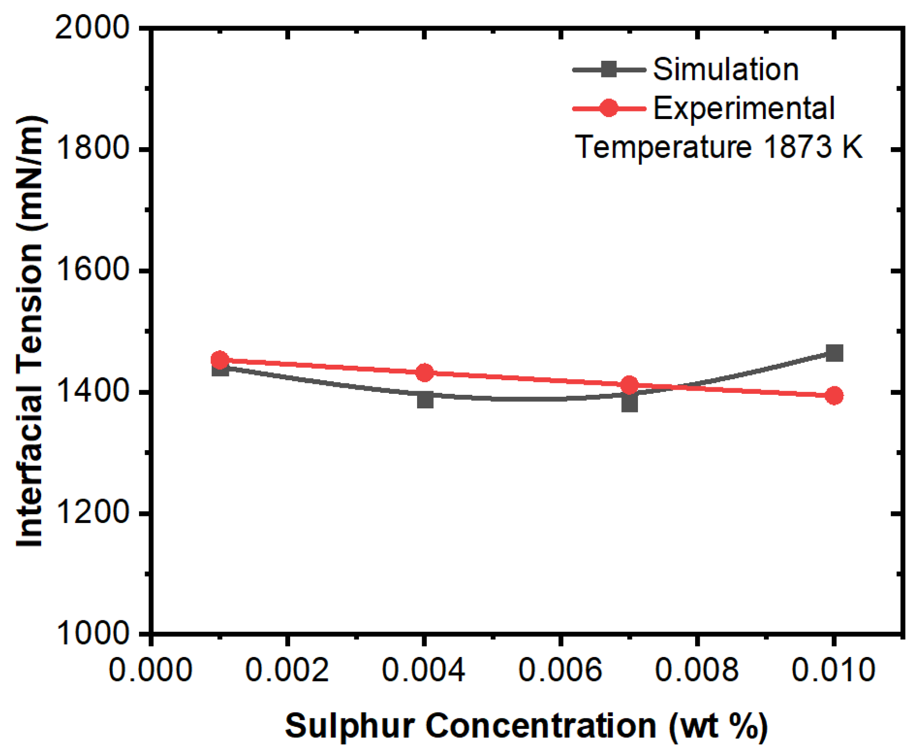
Effect of Interfacial Tension
4. Conclusions
- The Marangoni effect in the mold region was induced by the difference in temperature and sulfur content. The projected results demonstrate that inclusions were susceptible to engulfment by the solidification front under the influence of a larger surface tension differential between the inclusions and melt.
- Interfacial tension had a considerable impact on the motion behavior of the inclusion particle. It was observed that the inclusion movement at the solid–liquid interface was influenced by the sulfur content of the micro-alloyed steel. It was also observed that the moving solid contact captured inclusion particles.
- The projected results demonstrated that inclusions were susceptible to being engulfed by the solidification front under the influence of a larger surface tension differential between the inclusions and melt. A rise in sulfur content (to 100 ppm) had no discernible effect.
- We concluded that sulfur may preferentially concentrate near the interface during solidification, resulting in a concentration differential in the boundary layer. This phenomenon showed agreement with the numerical results, where a surfactant concentration gradient existed near the boundary layer and a higher amount of inclusion particles moved towards the solidifying boundary.
Author Contributions
Funding
Institutional Review Board Statement
Informed Consent Statement
Data Availability Statement
Acknowledgments
Conflicts of Interest
References
- Emi, T. Steelmaking Technology for the Last 100 Years: Toward Highly Efficient Mass Production Systems for High Quality Steels. ISIJ Int. 2015, 55, 36–66. [Google Scholar] [CrossRef]
- Sahai, Y. Tundish Technology for Casting Clean Steel: A Review. Met. Mater. Trans. B 2016, 47, 2095–2106. [Google Scholar] [CrossRef]
- Sahai, Y.; Emi, T. Tundish Technology for Clean Steel Production; World Scientific: Singapore, 2007. [Google Scholar]
- Dekkers, R.; Leuven, K.U. Improvement of Steel Cleanliness. 2002. Available online: https://www.worldscientific.com/doi/epdf/10.1142/6426 (accessed on 15 November 2022).
- Mazumdar, D. Tundish Metallurgy: Towards Increased Productivity and Clean Steel. Trans. Indian Inst. Met. 2013, 66, 597–610. [Google Scholar] [CrossRef]
- Kovačič, M.; Župerl, U. Genetic programming in the steelmaking industry. Genet. Program. Evolvable Mach. 2020, 21, 99–128. [Google Scholar] [CrossRef]
- Siddiqui, I.H.; Kim, M.-H. Two-Phase Numerical Modeling of Grade Intermixing in a Steelmaking Tundish. Metals 2019, 9, 40. [Google Scholar] [CrossRef]
- Luo, Y.; Ji, C.; He, W.; Liu, Y.; Yang, X.; Li, H. Fluid flow and heat transfer with nail dipping method in mould during continuous casting process. Can. Met. Q. 2020, 59, 201–210. [Google Scholar] [CrossRef]
- Balachandran, G. Challenges in Special Steel Making. IOP Conf. Series: Mater. Sci. Eng. 2018, 314, 012016. [Google Scholar] [CrossRef]
- Yang, Y.; Zhan, D.; Qiu, G.; Li, X.; Jiang, Z.; Zhang, H. Inclusion evolution in solid steel during rolling deformation: A review. J. Mater. Res. Technol. 2022, 18, 5103–5115. [Google Scholar] [CrossRef]
- Shi, S.-C.; Wang, W.-C.; Ko, D.-K. Influence of Inclusions on Mechanical Properties in Flash Butt Welding Joint of High-Strength Low-Alloy Steel. Metals 2022, 12, 242. [Google Scholar] [CrossRef]
- Sun, M.; Jiang, Z.; Li, Y.; Chen, C.; Ma, S.; Ji, Y.; Wang, J.; Liu, H. Effect of Sulfur Content on the Inclusion and Mechanical Properties in Ce-Mg Treated Resulfurized SCr420H Steel. Metals 2022, 12, 136. [Google Scholar] [CrossRef]
- Amer, A.E.; Halfa, H.; Ibrahim, K.M. Microstructure and Mechanical Properties of Advanced High-Silicon Austempered Steel. Met. Microstruct. Anal. 2022, 11, 454–466. [Google Scholar] [CrossRef]
- Mata-Rodríguez, M. Evolution of Inclusion Populations in Al-killed Steel during the Steelmaking Process; Elsevier: Amsterdam, The Netherlands, 2022; Available online: https://www.sciencedirect.com/science/article/pii/S223878542201643X (accessed on 14 November 2022).
- Chu, R.; Li, Z.; Malfliet, A.; Blanpain, B.; Guo, M. Growth mechanism of Al-Ti-O inclusions in steelmaking process. Met. Res. Technol. 2022, 119, 209. [Google Scholar] [CrossRef]
- Prithiv, T.; Thirumurugan, G. Thermodynamic Assessment of Steelmaking Practices for the Production of Re-Sulfur Steels; Springer: Berlin/Heidelberg, Germany, 2020; Available online: https://idp.springer.com/authorize/casa?redirect_uri=https://link.springer.com/article/10.1007/s12666-020-01941-9&casa_token=hgFY0J38C-UAAAAA:T8mPqmMVR06atrCPjE2hLAOFPEso4taO7DXxTLdiQJd1HzYlND5gLipDxqKV7dU54USIYU9Y6eb-I0Nfmw (accessed on 14 November 2022).
- Li, M.; Xu, Q. Evolution of Nonmetallic Inclusion during Steelmaking Process of Cold Heading Steel SWRCH35K. Available online: https://www.scirp.org/journal/paperinformation.aspx?paperid=120061 (accessed on 14 November 2022).
- Kerber, F.; Zienert, T.; Hubálková, J.; Stein, V.; Schemmel, T.; Jansen, H.; Aneziris, C.G. Effect of MgO Grade in MgO–C Refractories on the Non-metallic Inclusion Population in Al-Treated Steel. Steel Res. Int. 2021, 93, 2100482. [Google Scholar] [CrossRef]
- Kim, W.; Nam, G.; Kim, S.-Y. Evolution of Non-Metallic Inclusions in Al-killed Stainless Steelmaking; Springer: Berlin/Heidelberg, Germany, 2021; Available online: https://idp.springer.com/authorize/casa?redirect_uri=https://link.springer.com/article/10.1007/s11663-021-02119-4&casa_token=DomLFCu2GhQAAAAA:oGpWq8t58B52tXVn0p_GKmcU3O_B_cMufwvPDa5PMs2r_I4ndOwJ_p7N3RQGK3KhQSH8CPYlsdIQXK_ZdQ (accessed on 14 November 2022).
- Kamaraj, A.; Murugaiyan, P.; Mandal, G.K.; Roy, G.G. The Role of Slag Carryover on the Non-metallic Inclusion Evolution and Magnetic Behavior in Electrical Steel. Met. Mater. Trans. B 2022, 53, 1989–2003. [Google Scholar] [CrossRef]
- Kaushik, P.; Lehmann, J.; Nadif, M. State of the Art in Control of Inclusions, Their Characterization, and Future Requirements. Met. Mater. Trans. B 2012, 43, 710–725. [Google Scholar] [CrossRef]
- Zhang, L.; Thomas, B.G. Inclusions in continuous casting of steel. In XXIV National Steelmaking Symposium, Morelia, Mich, Mexico. 2003, pp. 138–183. Available online: http://ccc.illinois.edu/PDFFiles/Publications/03_Mexico_Nov_Inclusion_review_v5a_updated.pdf (accessed on 27 December 2012).
- Park, J.H.; Kang, Y. Inclusions in Stainless Steels—A Review. Steel Res. Int. 2017, 88, 1700130. [Google Scholar] [CrossRef]
- Zhang, L.; Ren, Q.; Duan, H.; Ren, Y.; Chen, W.; Cheng, G.; Yang, W.; Sridhar, S. Modelling of non-metallic inclusions in steel. Miner. Process. Extr. Met. 2020, 129, 184–206. [Google Scholar] [CrossRef]
- Jeong, J.; Park, D.; Shim, S.; Na, H.; Bae, G.; Seo, S.J.; Lee, J. Interfacial tension between SPFH590 microalloyed steel and alumina. Metall. Mater. Trans. B. 2019, 51, 690–696. [Google Scholar] [CrossRef]
- Jeong, J.; Park, D.; Shim, S.; Na, H.; Bae, G.; Seo, S.-J.; Lee, J. Prediction of Behavior of Alumina Inclusion in Front of Solid–Liquid Interface in SPFH590 Steel. Met. Mater. Trans. B 2020, 51, 690–696. [Google Scholar] [CrossRef]
- Siddiqui, I.H.; Maurya, A.; Ashraf, M.; Asiri, F. Modeling of Inclusion Motion Under Interfacial Tension in a Flash Welding Process; CRC Press: Boca Raton, FL, USA, 2021; pp. 91–110. [Google Scholar]
- Siddiqui, I.H.; Alshehri, H.; Orfi, J.; Ali, M.; Dobrotă, D. Computational Fluid Dynamics (CFD) Simulation of Inclusion Motion under Interfacial Tension in a Flash Welding Process. Metals 2021, 11, 1073. [Google Scholar] [CrossRef]
- Wu, M.; Ludwig, A.; Ratke, L. Modeling of marangoni-induced droplet motion and melt convection during solidification of hypermonotectic alloys. Met. Mater. Trans. A 2003, 34, 3009–3019. [Google Scholar] [CrossRef]
- Yin, H.; Emi, T. Marangoni flow at the gas/melt interface of steel. Metall. Mater. Trans. B 2003, 34, 483–493. [Google Scholar] [CrossRef]
- Cho, D.; Park, Y.-D.; Cheepu, M. Numerical Simulation of Slag Movement from Marangoni Flow for GMAW with Computational Fluid Dynamics; Elsevier: Amsterdam, The Netherlands, 2021; Available online: https://www.sciencedirect.com/science/article/pii/S0735193321001378?casa_token=ox5IBOazB_QAAAAA:i8tRzcIEmCJTdKP6xX-1HYlakEaS2yg2CAzoOfb6MvEvI2q_lHlvwmtuSdFsQT15yr-p-fhvQYY (accessed on 30 September 2021).
- Mukai, K.; Zeze, M.; Morohoshi, T. Motion of Fine Particles under Interfacial Tension Gradient in Relation to Solidification of Steel. Mater. Sci. Forum 2006, 508, 211–220. [Google Scholar] [CrossRef]
- Wang, Z.; Mukai, K.; Lee, I.J. Behavior of Fine Bubbles in Front of the Solidifying Interface. ISIJ Int. 1999, 39, 553–562. [Google Scholar] [CrossRef]
- Matsushita, T.; Mukai, K.; Zeze, M. Correspondence between Surface Tension Estimated by a Surface Thermodynamic Model and Number of Bubbles in the Vicinity of the Surface of Steel Products in Continuous Casting Process. ISIJ Int. 2013, 53, 18–26. [Google Scholar] [CrossRef]
- Scheller, P.R.; Lee, J.; Yoshikwa, T.; Tanaka, T. Applications of Interfacial Phenomena in Process Metallurgy. Treatise Process Metall. 2014, 2, 119–139. [Google Scholar] [CrossRef]
- Ogino, K.; Nogi, K.; Koshida, Y. Effect of Oxygen on the Wettability of Solid Oxide with Molten Iron. Tetsu-To-Hagane 1973, 59, 1380–1387. [Google Scholar] [CrossRef]
- Tanaka, T.; Goto, H.; Nakamoto, M.; Suzuki, M.; Hanao, M.; Zeze, M.; Yamamura, H.; Yoshikawa, T. Dynamic Changes in Interfacial Tension between Liquid Fe Alloy and Molten Slag Induced by Chemical Reactions. ISIJ Int. 2016, 56, 944–952. [Google Scholar] [CrossRef]
- Nikolopoulos, P. Surface, grain-boundary and interfacial energies in Al2O3 and Al2O3-Sn, Al2O3-Co systems. J. Mater. Sci. 1985, 20, 3993–4000. [Google Scholar] [CrossRef]
- Evaluation of Interfacial Energy between Molten Fe and Fe-18%Cr-9%Ni Alloy and Non-Metallic Inclusion-Type Oxides. Available online: https://www.jstage.jst.go.jp/article/isijinternational/61/9/61_ISIJINT-2020-696/_article/-char/ja/ (accessed on 10 November 2022).
- Fukami, N.; Wakamatsu, R.; Shinozaki, N.; Wasai, K. Wettability between Porous MgAl2O4 Substrates and Molten Iron. J. Jpn. Inst. Met. Mater. 2010, 74, 650–655. [Google Scholar] [CrossRef][Green Version]
- Gao, E.; Zou, G.; Wang, W.; Ma, F.; Luo, X. Undercooling and Wettability Behavior of Interstitial-Free Steel on TiN, Al2O3 and MgAl2O4 Under Controlled Oxygen Partial Pressure. Met. Mater. Trans. B 2016, 48, 1014–1023. [Google Scholar] [CrossRef]
- Choe, J.; Kim, H.G.; Kang, Y.; Lee, J. Investigation of Degree of Undercooling of Fe-O Alloy on Al2O3 Substrate. Met. Mater. Trans. B 2014, 45, 1589–1592. [Google Scholar] [CrossRef]
- Lee, J.; Shin, M.; Park, J.H.; Seetharaman, S. Studies of wetting characteristics of liquid Fe–Cr alloys on oxide substrates by sessile drop technique. Ironmak. Steelmak. 2010, 37, 512–515. [Google Scholar] [CrossRef]
- Mukai, K.; Li, Z.; Zeze, M. Surface Tension and Wettability of Liquid Fe-16 mass%Cr-O Alloy with Alumina. Mater. Trans. 2002, 43, 1724–1731. [Google Scholar] [CrossRef]
- Sasai, K. Direct Measurement of Agglomeration Force Exerted between Alumina Particles in Molten Steel. ISIJ Int. 2014, 54, 2780–2789. [Google Scholar] [CrossRef]
- Park, J.H.; Todoroki, H. Control of MgO·Al2O3 Spinel Inclusions in Stainless Steels. ISIJ Int. 2010, 50, 1333–1346. [Google Scholar] [CrossRef]
- Nakajima, K. Estimation of Interfacial Tensions between Phases in the Molten Iron-Slag-Inclusion (Alumina) System. Tetsu-To-Hagane 1994, 80, 383–388. [Google Scholar] [CrossRef]
- Nakamoto, M.; Tanaka, T.; Suzuki, M.; Taguchi, K.; Tsukaguchi, Y.; Yamamoto, T. Effects of Interfacial Properties between Molten Iron and Alumina on Neck Growth of Alumina Balls at Sintering in Molten Iron. ISIJ Int. 2014, 54, 1195–1203. [Google Scholar] [CrossRef]
- Shen, P.; Zhang, L.; Zhou, H.; Ren, Y.; Wang, Y. Wettability between Fe-Al alloy and sintered MgO. Ceram. Int. 2017, 43, 7674–7681. [Google Scholar] [CrossRef]
- Siddiqui, I.H.; Albaqami, A.; Arifudin, L.; Alluhydan, K.; Alnaser, I.A. Simulation of Inclusion Particle Motion Behavior under Interfacial Tension in Continuous Casting Mold. Materials 2022, 15, 7458. [Google Scholar] [CrossRef]
- Speiser, R. The physical properties of liquid metals: By T. Iida and R. I. L. Gutthrie; published by Clarendon Press, Oxford, 1988; 288 pp.; price, £40.00. Mater. Sci. Eng. A 1989, 114, 215–216. [Google Scholar] [CrossRef]
- Maurya, A.; Jha, P.K. Influence of electromagnetic stirrer position on fluid flow and solidification in continuous casting mold. Appl. Math. Model. 2017, 48, 736–748. [Google Scholar] [CrossRef]
- Siddiqui, I.H.; Geleta, D.D.; Bae, G.; Lee, J. Numerical Modeling of the Inclusion Behavior during AC Flash Butt Welding. ISIJ Int. 2020, 60, 2503–2511. [Google Scholar] [CrossRef]
- Richter, O.; Turnow, J.; Kornev, N.; Hassel, E. Numerical simulation of casting processes: Coupled mould filling and solidification using VOF and enthalpy-porosity method. Heat Mass Transf. 2016, 53, 1957–1969. [Google Scholar] [CrossRef]
- Hirt, C.W.; Nichols, B.D. Volume of fluid (VOF) method for the dynamics of free boundaries. J. Comput. Phys. 1981, 39, 201–225. [Google Scholar] [CrossRef]
- Cho, S.-M.; Thomas, B.; Hwang, J.-Y.; Bang, J.-G.; Bae, I.-S. Modeling of Inclusion Capture in a Steel Slab Caster with Vertical Section and Bending. Metals 2021, 11, 654. [Google Scholar] [CrossRef]


| Element | C | Mn | Si | P | Al | Nb |
|---|---|---|---|---|---|---|
| Concentration | ≤0.1 | ≤3.0 | ≤0.5 | ≤0.1 | ≤0.1 | ≤0.1 |
| Parameters | Values |
|---|---|
| Density of molten steel [51] | ρ (kg m−3) = 8621.17 − 0.88 T |
| The viscosity of molten steel [51] | μ (mPa s) = 0.2388*exp(47.44/(RT)) |
| Specific heat [52] | 750 J kg−1 K−1 |
| Thermal conductivity [52] | 41 W m−1 K−1 |
| Surface tension (σL) and interfacial tension (σPL) | Shown in Equations (11) and (12) [25,26] |
| Solidus temperature | 1781 K |
| Liquidus temperature | 1798 K |
| Alumina inclusion size | 300 μm |
| Process Parameters | Values |
|---|---|
| Mold width | 1500 mm |
| Mold length | 3600 mm |
| SEN submergence depth | 160 mm |
| Nozzle port downward angle | 15 degree |
| Inlet velocity | 2 m/s |
| Outlet | Pressure outlet condition |
| Alumina inclusion density | 2500 kg/m3 |
| Shell surface temperature | 1273 K |
| Mold conductivity | 315 W/mk |
| Latent heat | 272,000 (J/kg) |
Disclaimer/Publisher’s Note: The statements, opinions and data contained in all publications are solely those of the individual author(s) and contributor(s) and not of MDPI and/or the editor(s). MDPI and/or the editor(s) disclaim responsibility for any injury to people or property resulting from any ideas, methods, instructions or products referred to in the content. |
© 2023 by the authors. Licensee MDPI, Basel, Switzerland. This article is an open access article distributed under the terms and conditions of the Creative Commons Attribution (CC BY) license (https://creativecommons.org/licenses/by/4.0/).
Share and Cite
Siddiqui, M.I.H.; Arifudin, L.; Alnaser, I.A.; Ali, M.A.; Alluhydan, K. Modeling of Interfacial Tension and Inclusion Motion Behavior in Steelmaking Continuous Casting Mold. Materials 2023, 16, 968. https://doi.org/10.3390/ma16030968
Siddiqui MIH, Arifudin L, Alnaser IA, Ali MA, Alluhydan K. Modeling of Interfacial Tension and Inclusion Motion Behavior in Steelmaking Continuous Casting Mold. Materials. 2023; 16(3):968. https://doi.org/10.3390/ma16030968
Chicago/Turabian StyleSiddiqui, Md Irfanul Haque, Latif Arifudin, Ibrahim Abdullah Alnaser, Masood Ashraf Ali, and Khalid Alluhydan. 2023. "Modeling of Interfacial Tension and Inclusion Motion Behavior in Steelmaking Continuous Casting Mold" Materials 16, no. 3: 968. https://doi.org/10.3390/ma16030968
APA StyleSiddiqui, M. I. H., Arifudin, L., Alnaser, I. A., Ali, M. A., & Alluhydan, K. (2023). Modeling of Interfacial Tension and Inclusion Motion Behavior in Steelmaking Continuous Casting Mold. Materials, 16(3), 968. https://doi.org/10.3390/ma16030968