Article

Mechanical Performance, Microstructure, and Porosity Evolution of Fly Ash Geopolymer after Ten Years of Curing Age

by
Ikmal Hakem A. Aziz
1,*,
Mohd Mustafa Al Bakri Abdullah
1,2,*,
Rafiza Abd Razak
1,3,
Zarina Yahya
1,3,
Mohd Arif Anuar Mohd Salleh
1,2,
Jitrin Chaiprapa
4,
Catleya Rojviriya
4,
Petrica Vizureanu
5,*,
Andrei Victor Sandu
5,
Muhammad FaheemMohd Tahir
1,2,
Alida Abdullah
1,6 and
Liyana Jamaludin
1,6
1
Centre of Excellence Geopolymer & Green Technology (CEGeoGTech), Universiti Malaysia Perlis (UniMAP), Perlis 01000, Malaysia
2
Faculty of Chemical Engineering Technology, Universiti Malaysia Perlis (UniMAP), Perlis 01000, Malaysia
3
Faculty of Civil Engineering Technology, Universiti Malaysia Perlis (UniMAP), Perlis 01000, Malaysia
4
Synchrotron Light Research Institute, Muang, Nakhon Ratchasima 30000, Thailand
5
Faculty of Material Science and Engineering, Gheorghe Asachi Technical University of Iasi, 41 D. Mangeron St., 700050 Iasi, Romania
6
Faculty of Mechanical Engineering Technology, Universiti Malaysia Perlis (UniMAP), Perlis 01000, Malaysia
*
Authors to whom correspondence should be addressed.
Materials 2023, 16(3), 1096; https://doi.org/10.3390/ma16031096
Submission received: 25 July 2022 / Revised: 27 September 2022 / Accepted: 29 September 2022 / Published: 27 January 2023
(This article belongs to the Special Issue New Geopolymers Used in Civil Engineering)

Abstract

:
This paper elucidates the mechanical performance, microstructure, and porosity evolution of fly ash geopolymer after 10 years of curing age. Given their wide range of applications, understanding the microstructure of geopolymers is critical for their long-term use. The outcome of fly ash geopolymer on mechanical performance and microstructural characteristics was compared between 28 days of curing (FA28D) and after 10 years of curing age (FA10Y) at similar mixing designs. The results of this work reveal that the FA10Y has a beneficial effect on strength development and denser microstructure compared to FA28D. The total porosity of FA10Y was also lower than FA28D due to the anorthite formation resulting in the compacted matrix. After 10 years of curing age, the 3D pore distribution showed a considerable decrease in the range of 5–30 µm with the formation of isolated and intergranular holes.

1. Introduction

Geopolymer material has engineering qualities that are similar to OPC concrete [1], depending on the type of precursor used. Moreover, geopolymer is a supplementary cementitious material that has received significant attention in recent decades [2,3]. The compositions of the silica/alumina sources and the type of alkaline activators have a substantial influence on the properties of geopolymer. These properties can be initiated by using locally available precursors and the optimal activator dosage in geopolymer synthesis. Several countries are conducting research on geopolymer materials. The tremendous application possibilities have sparked increased interest in this technology, which is considered relatively innovative by current binder standards. However, its industrial spread and acceptability require more research into the various variables involved in its processing and service life.
According to De Vargas et al. [4], it is important to evaluate the various factors that are critical to ensuring effective polymerization of the raw material, such as reactive (amorphous) silicon concentration, glassy state level, and particle size distribution. The performance of the geopolymer structure will be mostly determined by the availability of ions in the solution to form a chemical bond. Ions from silicon, aluminum, and free oxygen coordinately bond during the reaction to produce inorganic polymer chains [5]. Sekou et al. [6] said that mixing suitable amounts of amorphous silica/alumina with the alkaline activator stimulates particle disintegration due to the high alkalinity in the medium, resulting in lixiviation and subsequent reactivity of the Al and Si ions. The coordinated Si–Al bonds formed with O are then exploited to generate monomers, which condense and precipitate as a gel. The final stage occurs when the majority of the available material in the reaction has organised into polymer(silates). When large proportions of inorganic polymers are generated and have hardened the geopolymer structure, the reaction is interrupted.
In term of mechanical performance, several experiments have been conducted in order to establish the durability performance of geopolymer material. The durability of the structure in an open environment is affected by the microstructure and crystalline evolution. According to Wong et al. [7], curing times up to 91 days have been demonstrated to boost strength even further. The dominance of calcium aluminium silicate hydrate (C–A–S–H) gel in the geopolymer system is related to the development strength. The curing temperature has an impact on the cement’s quality and durability [8]. Santa et al. [5] studied the microstructural evaluation in geopolymer samples after 8 years of curing age. Over the years, no structural degradation and denser microstructure were observed for the 8 years samples, hence, it may be related to long-term durability.
There are certain limitations to the traditional scanning electron microscopy (SEM) approach, which only offers pore shape assumptions and phase connectivity information in 2D images [9]. Otherwise, if standard X-ray tomography (µ-CT) is utilized, it is difficult to obtain a highlight-connected pore network for geopolymer material from the segmented pore [10]. Synchrotron X-ray tomography (SXTM) produces a high-resolution three-dimensional picture of pores and network arrangement [11]. Evaluating the microstructural properties of geopolymer in the short and long term is critical for identifying potential changes of structure degradation. More knowledge on these materials can help ensure their use in building projects as well as other fields that require new binders with distinct qualities.
An enormous number of works on geopolymer materials in the literature strive to understand the early phase of their development. In most situations, the samples were examined after ninety days of curing [12,13,14,15]. A deeper knowledge of the various alterations that occur in geopolymers following synthesis is critical in this context. Hence, certain samples were produced and preserved for 10 years to increase knowledge of geopolymer structure. Consequently, the aim of this work is to perform a mechanical and microstructural examination of a geopolymer sample in the early phases of curing (28 days), as well as samples of geopolymers preserved for more than 10 years.

2. Materials and Methods

The fly ash for this work was supplied by the Manjung Power Station in Lumut, Perak, Malaysia. X-ray fluorescence (XRF) was used to determine the chemical composition of the fly ash, as tabulated in Table 1. Due to the calcium oxide (CaO) level being greater than 10%, it can be categorized as Class-C fly ash according to ASTM C618-08 [16]. The fly ash was activated with an alkaline activator made by combining a technical grade sodium silicate (Na2SiO3) solution with sodium hydroxide (NaOH). The Na2SiO3 chemical composition was SiO2 = 30.1%, Na2O = 9.4%, and H2O = 60.5%, and the modulus ratio was 2 (where MS = SiO2/Na2O). The NaOH of 12 M was made by combining 97–99% pure sodium hydroxide pellets with distilled water. The alkaline activator was created by combining a 1:1 constant mass ratio of Na2SiO3 with 12 M NaOH solution.

2.1. Mixing of the Geopolymer Aggregate

In a 5 L quantity, the fly ash was mixed with the advanced prepared alkaline activator liquid for around 5 min to fabricate the geopolymer aggregate. The slurry was then poured into 100 mm × 100 mm × 100 mm cubic plastic molds, which were the dimensions of the samples. The specimens were then vibrated for 2 min on a vibrating table to expel any remaining air bubbles. During the hardening process, the geopolymer samples were coated with a thin coating of polyethylene to prevent water evaporation and then maintained in the laboratory for 24 h at ambient temperature before demolding. After demolding, the samples were coated with a thin layer of polyethylene for 28 days prior to measuring the compressive strength. Samples with the similar mixing design were prepared and set aside for curing at different time intervals. For each mixing design, the different curing period of fly ash-based geopolymer was investigated. Hence, two designs were synthesized. For instance, FA28D refers to the samples cured at 28 days, while FA10Y refers to the samples cured for 10 years. All the samples were stored in the laboratory at room temperature until the testing days.

2.2. Characterization Techniques

2.2.1. Compressive Measurement and Microstructural Characterization

To determine the ultimate strength of the geopolymer, a compressive strength test was performed on a geopolymer aggregate sample in line with BS 1881-116:1983. The sample loaded had a force of 50.00 kN (11.24 Kips) and a loading speed of 5.00 mm/min (0.20 in./min). The loading pace rate was 0.1 kN/s (22.48 lb/s).
Using a JSM-6460LA model Scanning Electron Microscope (JOEL, Peabody, MA, USA) equipped with a secondary electron detector and energy-dispersive X-ray spectroscopy, the microstructural changes of the fly ash geopolymer were investigated. The fracture sample was cut into small pieces prior to the analysis. Palladium was used to coat the samples. The microstructure investigation was performed at 10 kV acceleration voltages and a working distance of 10 mm.

2.2.2. X-ray Diffraction (XRD) Analysis

Shimadzu X-ray diffractometer XRD-6000 was used for phase analysis. The specimen was used for phase analysis. The specimen for analysis was processed as a powder. The XRD examination was carried out with Cu K radiation (λ = 1.5418 A) at 40 kV, 30 mA, at 2θ ranging between 10° and 80° with a scan rate of 1°/min. X’pert High score Plus software was used to analyse the XRD pattern (Columbia City, IN, USA).

2.2.3. Synchrotron Micro X-ray Fluorescence (µ-XRF) and X-ray Tomographic Microscopy (SXTM)

The elemental distribution of the fly ash geopolymer was determined by Synchrotron-based µ-XRF. The experiments were carried out at Beamline 7.2 W, Synchrotron Light Research Institute (SLRI), Thailand. At BL 7.2 W, the synchrotron radiation was produced from a 6.5 T superconducting wavelength shifter. With Si(111) double crystal monochromator, 12 keV of the monochromatic X-ray beam was exploited in the experiments. The polycapillary half-lens, used to focus the X-ray beam, delivered a micro X-ray beam with the size of 25 × 25 μm2 onto the specimen in which the incident micro X-ray beam was perpendicular to the specimen (Bangkok, Thailand).
The single element Vortex EM-650 silicon drift detector was placed was placed 45 degrees to the specimen to collect fluorescent X-rays emitted from the specimen, while the ccd camera, positioned parallel to the beam and perpendicular to the specimen, was used for area selection of the specimen. For this experiment, 0.3 × 0.3 mm2 of the region of interest on the sample was selected, and the scanning step 30 μm in horizontal and 30 μm in vertical was selected for raster scanning. Thus, the elemental distribution maps were collected using a 68 μm (h) × 35 μm (v) pixel size. The dwell time for each point was 30 s. The XRF spectra were analysed using PyMCA version 5.6.5 [17], which was developed by the Software Group of the European Synchrotron Radiation Facility (ESRF) (http://pymca.sourceforge.net/PyMca, accessed on 31 August 2020).
To prevent displacement and dehydration during tomographic scanning, each sample was placed in a cylindrical sample holder filled with cotton soaked in formaldehyde solution. SXTM experiments were carried out at the Synchrotron XTM beamline (BL 1.2 W: X-ray imaging and tomographic microscopy), Synchrotron Light Research Institute, Thailand. SXTM imaging of the fly ash geopolymer was performed at a distance of 34 m from the source using a filtered polychromatic X-ray beam with a maximum area of 4 × 8 mm2 at 10 keV [18]. The sample projections had a 200-µm-thick YAG:Ce scintillator, a white beam microscope (Optique Peter, France), and a pco.edge 5.5 sCMOS camera (2560 × 2160 pixels, 16 bits). The entire tomographic scan was taken at a pixel size of 1.44 µm, which offered a field of views (3.1 × 3.7 mm2). To identify the fine features of the fly ash geopolymer, two reconstruction tomographic volume scans were performed. The first scan was acquired over 180°, and the second scan was captured on the vertical axis of rotation as displaced parallel and horizontal to the actual camera [19]. The X-ray projection was then normalized by flat-field correction, patched, and reconstructed with Octopus software [20]. Drishti software was used to create 3D images of tomographic volume.

3. Results and Discussion

3.1. Compressive Strength Measurement

Figure 1a depicts the compressive strength of fly ash geopolymer aggregates at various fly ash/aggregate ratios at 28 days of curing. The results exemplified that the fly ash/aggregate ratios of 30/70 obtained the highest compressive strength (49.3 MPa) after 28 days of curing. When the fly ash content is too low (20% of dry weight) or too high (50–40% of dry weight), the compressive strength is insufficient. This suggests that high aggregate content in the geopolymer mixture does not guarantee high strength production. The presence of total fly ash further promotes the geopolymerization process. However, fly ash content less that than 20% causes the geopolymerization reaction to be less efficient, resulting in lower strength. Incorporation of aggregate and calcium source materials developed the compressive strength.
In order to evaluate the effect of curing age on the mechanical performance of the 28 days (FA28D) and 10 years (FA10Y), the highest fly ash/aggregate ratio (30/70) was selected for further investigations. After 10 years of curing age, the strength of the materials increased slightly as shown in Figure 1b. The FA10Y samples recorded the higher compressive strength (87.32 MPa), and the FA28D displayed the lower compressive strength (49.3 MPa). The impressive enormous rise in strength was mostly due to an increase in curing time for highly hardened samples, which played a vital role in the higher strength. The formation of a compacted microstructure will be discussed in the next section.

3.2. SEM

To determine the microstructure of fly ash geopolymer samples after 28 days and 10 years curing age, the fractured pieces were subjected to SEM/EDS analysis (Figure 2a–f). For samples at 28 days curing age (Figure 2a–c), fly ash particles were clearly unreacted and did not participate in the polymerization. Additionally, cracks and voids were also obtained indicating a permeable of geopolymer samples as depicted in Figure 2b. Cracks and voids were also discovered, which suggested that the geopolymer samples were porous. Furthermore, a micro crack in the microstructure pointed to inappropriate bonding of the geopolymer aggregate.
The morphologies of hardened samples after 10 years curing age are shown in Figure 2d–f. The samples have smaller pores than 28-day samples as seen in Figure 2e. The quality and durability of the samples are influenced by the curing temperature. In order to maintain uniform hydration, curing must be performed at temperatures that allow the moisture content to be sustained close to saturation. According to Lee et al. [21], long-term durability could be related to the properties and quantities of the pores present in the materials. The geopolymer binder contains pores that allowed liquid or gaseous agent to enter, leading to corrosion and shortening the material’s useful life. Hence, it is crucial to emphasize that a material’s curing age impact decreases as it become more durable.
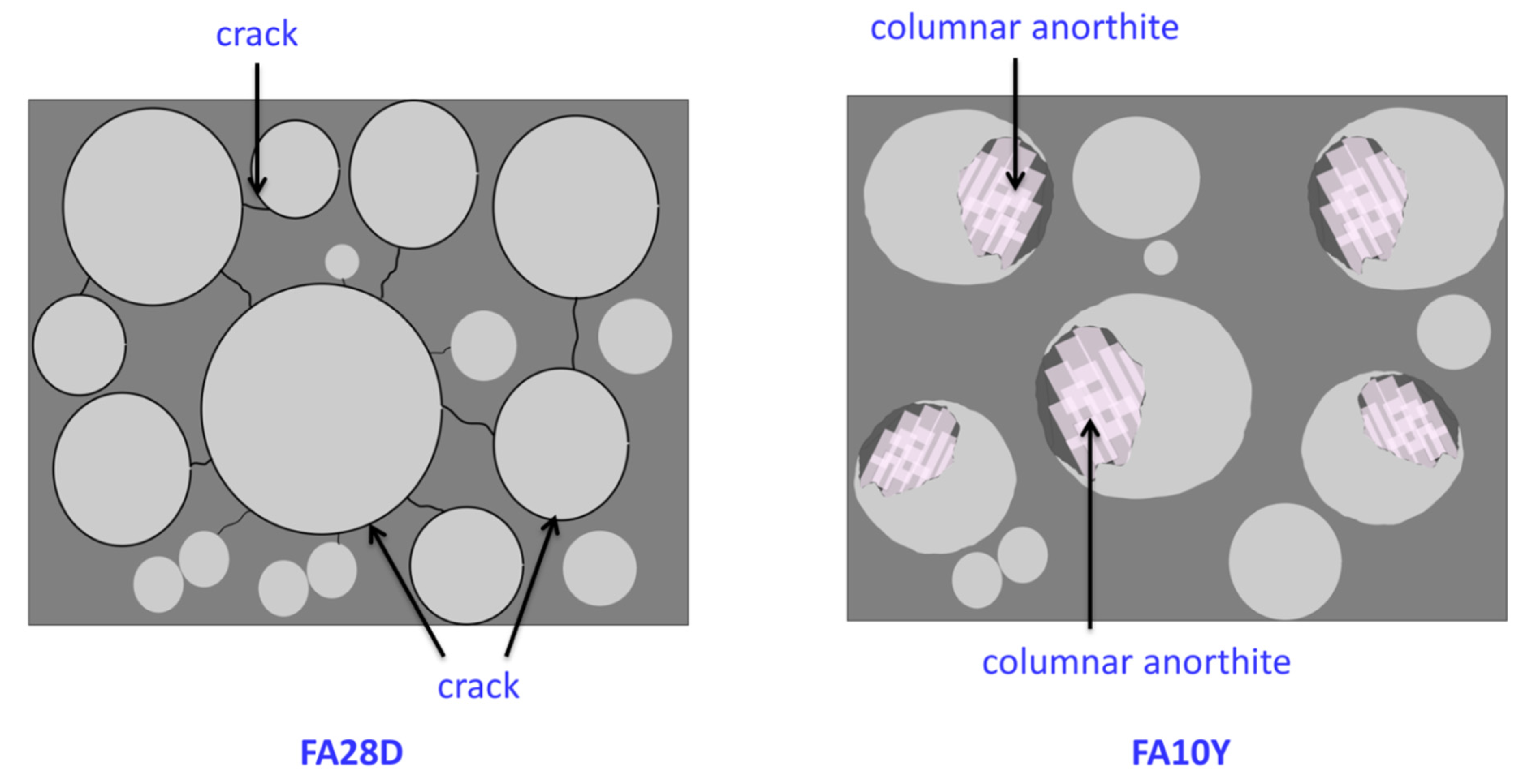
The SEM images with larger magnification (5000×) depict an obvious crystallite formation in 10 years curing age samples with less crack and voids, respectively. In the amorphous geopolymer matrix, crystallites formed after prolonged curing age. Upon curing age up to 10 years, columnar anorthite crystal and plerospheres of thin-walled spherical fly ash [22] can be clearly seen in Figure 2f. The geopolymer matrix bonded the crystallites together. The existence of crystal was caused by the longer curing age of the fly ash geopolymer at room temperature. The anorthite crystal was indicated by the transformation of fly ash cenosphere as shown in Figure 3. The spherical transformation and denser surface were attributed to the necking reaction between particles (Figure 2f). The presence of crystal was thought to improve the compressive strength of the geopolymer as obtained in Section 3.1.

3.3. XRD and u-XRF

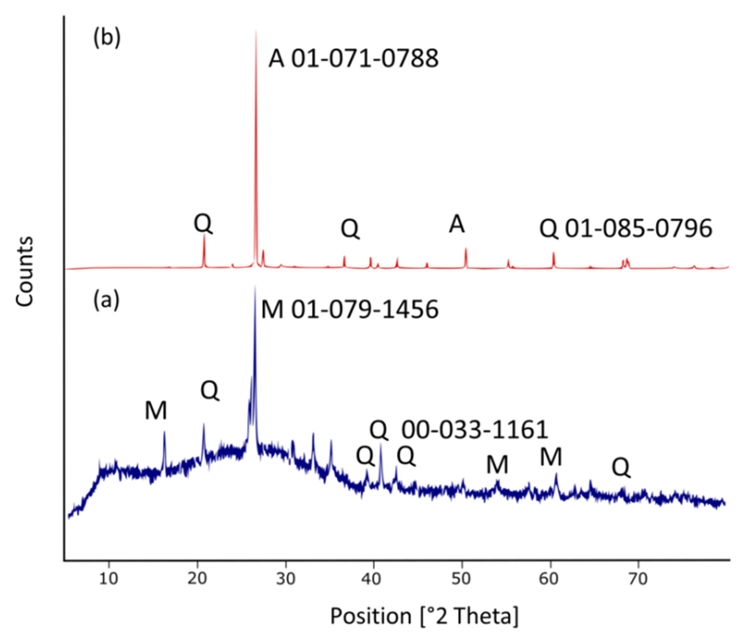
Figure 4 illustrates the XRD pattern of the fly ash geopolymer mortar at 28 days and 10 years curing age. M: mullite (Al6Si2O12), Q: quartz (SiO2), and A: anorthite (CaAl2SiO8) are the crystalline phase identified. The XRD diffractogram for the samples of 28 days curing age (Figure 4a) demonstrated an apparent wider amorphous halo. This might be due to the reorganization of the polymer chain and microstructure in the binder and the formation of semi-crystalline structure over 28 days. As shown in Figure 4a, the samples contained mullite and quartz as a major and minor phase, respectively. Mullite and quartz intensities rapidly decreased with longer days of curing age and eventually disappeared after 10 years.
In contrast, the intensity anorthite crystal gradually increased and after 10 years, showing that it can be totally produced after longer curing age. As a result, according to Equation (1) [22], the transformation of mullite into anorthite was completely by the following solid-state reactions:
Al6Si2O13 (mullite) + 6CaO + SiO2 (Quartz) → 3Ca2Al2SiO7 (gehlenite)
3Ca2Al2SiO7 (gehlenite) + Al6Si2O13 + 7SiO2 (mullite) → 6CaAl2Si2O8 (anorthite)
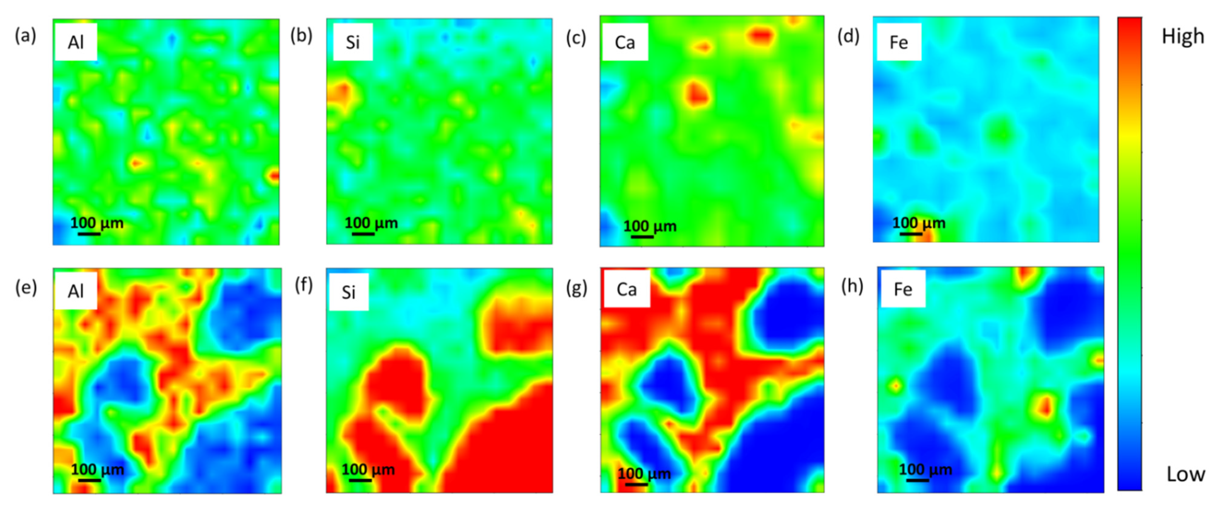
The fly ash geopolymer mortar was further examined using synchrotron micro-XRF mapping to gain a better understanding of the element distribution and the possibility for mullite and anorthite development of the curing age samples. Figure 5 depicts the localised area and micro-XRF mapping in the Al–Si–Ca–Fe of the fly ash geopolymer mortar, indicating that Al, Si, and Ca are predominantly located within the samples. The distribution of major elements, particularly light elements that may reflect mineral existence within the geopolymer structure, may be determined using synchrotron micro-XRF. For each distribution element in the integrated region, the colours red, green, and blue signify high, medium, and low intensities, respectively.
Figure 5a–d display the distribution of Si and Al map in geopolymer mortar of 28 days curing age which allowed for the identification of the geopolymer main chain (Si-O-Al/Si) and mullite minerals [23]. The Si represented the medium concentration (green) of Si element for the geopolymers, as demonstrated well by the sample homogeneity. Quartz grains are shown by the high concentration Si area (red). Furthermore, the localized high concentration of the Ca region (Figure 5c) is indicated by lime grains. The longer curing time resulted in considerable changes in the Al, Si, and Ca elemental distribution, resulting in the production of a stable crystalline phase and the significant formation of anorthite as shown in Figure 4b. After curing age up to 10 years, it can be visualised that Al, Si, and Ca are of high intensity in a localised area, reflecting the existence of an anorthite phase. The Ca-rich crystalline minerals are thought to contribute to the glassy and microstructure phase appearance [9]. In other previous studies, Zhang et al. [24], stated that the promotion of crystalline anorthite is due to the higher temperature exposure, while this current work obtained that the crystalline evolution of anorthite from mullite was attributed to the longer curing age.

3.4. XTM

Figure 6 depicts the total porosity and pore distribution of fly ash geopolymer mortar at 28 days and 10 years curing age. The majority of the pores in both samples were open, with only a few closed pores. The air occupancy in the sample was used to compute the total porosity, pore diameter, and pore volume. As depicted in Figure 6a, the total porosity of the 28 days curing age sample was 26.45% (25.89% of open pores and 0.56% of closed pores). The pore diameter of 28 days curing age was distributed in the range of 0–5 µm, and its pore volume was 51,353 µm3. According to Figure 4b, the total porosity of 10 years curing age sample was 11.04% (8.72% of open pores and 2.32% of closed pores). The pore diameter of the 10 years curing age sample was spread in the range of 0–5 µm, and its pore volume was 11,773.7 µm3. In comparison, the 10 years curing age samples had lower overall porosity, pore diameter, and pore volume than the 28 days curing age sample. The reduction in total porosity is due to longer evaporation and dehydroxylation in the geopolymer during the curing period, which generates an isolated pores network and yields a denser surface [11]. This observation is consistent with the finding of surface morphology (Figure 2).

4. Conclusions

The long-term performance of fly ash geopolymer material was evaluated after 10 years of curing age at room temperature. The following conclusions can be drawn from the test results:
  • The compressive strength for FA10Y was high compared to FA28D. Compared to FA28D, the compressive strength of FA10Y was approximately ~74% higher than the compressive strength of FA28D.
  • There are increasing densification surfaces and less total porosity within FA10Y compared to FA28D. The columnar anorthite crystal was obtained inside the fly ash spherical particles which contributed to the strength development.
  • The synchrotron micro X-ray tomography revealed a lower range (5–20 µm) of pore distribution and higher localized Al, Si, and Ca elements after 10 years of curing age.

Author Contributions

Conceptualization, I.H.A.A., M.M.A.B.A., R.A.R. and Z.Y.; methodology, I.H.A.A., M.A.A.M.S., M.F.T., A.A. and P.V.; resources, A.A., L.J., C.R. and M.F.T.; data extraction, I.H.A.A., J.C., C.R. and A.V.S.; writing—original draft preparation, I.H.A.A., M.M.A.B.A., R.A.R. and J.C.; writing—review and editing, I.H.A.A., P.V., A.V.S., C.R. and Z.Y.; project administration; I.H.A.A., L.J. and A.A.; supervision; M.M.A.B.A. and M.A.A.M.S.; funding acquisition; M.M.A.B.A., P.V. and A.V.S. All authors have read and agreed to the published version of the manuscript.

Funding

Malaysian Ministry of Education's (MOE) Fundamental Research Grant Scheme: Marie Skodowska-Curie RISE Grant Agreement (689857 H2020-MSCA-RISE-2015); TUIASI: University Scientific Research Fund (FCSU).

Institutional Review Board Statement

Not applicable.

Informed Consent Statement

Not applicable.

Data Availability Statement

Not applicable.

Acknowledgments

The authors would like to express their gratitude to the Centre of Excellence Geopolymer and Green Technology (CEGeoGTech) and the Faculty of Chemical Engineering Technology at UniMAP for their expertise and assistance. The authors would like to express their gratitude to the Malaysian Ministry of Education’s (MOE) Fundamental Research Grant Scheme and the “Partnership for Research in Geopolymer Concrete” under the scope of the Marie Skodowska-Curie RISE Grant Agreement (689857 H2020-MSCA-RISE-2015). We sincerely appreciate the technical support from the Synchrotron Light Research Institute (public organization), NakhonRatchasima, Thailand. This research was also supported by TUIASI from the University Scientific Research Fund (FCSU).

Conflicts of Interest

The authors declare no conflict of interest.

References

  1. Shahedan, N.F.; Abdullah, M.M.A.B.; Mahmed, N.; Kusbiantoro, A.; Tammas-Williams, S.; Li, L.-Y.; Aziz, I.H.; Vizureanu, P.; Wysłocki, J.J.; Błoch, K. Properties of a New Insulation Material Glass Bubble in Geopolymer Concrete. Materials 2021, 14, 809. [Google Scholar] [CrossRef] [PubMed]
  2. Luhar, I.; Luhar, S.; Abdullah, M.M.A.B.; Nabiałek, M.; Sandu, A.V.; Szmidla, J.; Jurczyńska, A.; Razak, R.A.; Aziz, I.H.A.; Jamil, N.H. Assessment of the suitability of ceramic waste in geopolymer composites: An appraisal. Materials 2021, 14, 3279. [Google Scholar] [CrossRef] [PubMed]
  3. Kheimi, M.; Aziz, I.H.; Abdullah, M.M.A.B.; Almadani, M.; Razak, R.A. Waste Material via Geopolymerization for Heavy-Duty Application: A Review. Materials 2022, 15, 3205. [Google Scholar] [CrossRef] [PubMed]
  4. De Vargas, A.S.; Molin, D.C.D.; Vilela, A.C.; da Silva, F.J.; Pavao, B.; Veit, H. The effects of Na2O/SiO2 molar ratio, curing temperature and age on compressive strength, morphology and microstructure of alkali-activated fly ash-based geopolymers. Cement Concr. Compos. 2011, 33, 653–660. [Google Scholar] [CrossRef]
  5. Santa, R.A.A.B.; Padoin, N.; Soares, C.; Riella, H.G. Microstructural characteristics of geopolymer materials with twenty eight days of curing and after eight years stored at room temperature. J. Clean. Prod. 2021, 278, 123437. [Google Scholar] [CrossRef]
  6. Sekou, T.; Sine, D.; Lanciné, T.D.; Bakaridjan, C. Synthesis and characterization of a red mud and rice husk based geopolymer for engineering applications. In Macromolecular Symposia; Wiley & Sons: Hoboken, NJ, USA, 2017. [Google Scholar]
  7. Wong, V.; Jervis, W.; Fishburn, B.; Numata, T.; Joe, W.; Rawal, A.; Sorrell, C.C.; Koshy, P. Long-Term Strength Evolution in Ambient-Cured Solid-Activator Geopolymer Compositions. Minerals 2021, 11, 143. [Google Scholar] [CrossRef]
  8. Alhazmi, H.; Shah, S.A.R.; Anwar, M.K.; Raza, A.; Ullah, M.K.; Iqbal, F. Utilization of Polymer Concrete Composites for a Circular Economy: A Comparative Review for Assessment of Recycling and Waste Utilization. Polymers 2021, 13, 2135. [Google Scholar] [CrossRef]
  9. Aziz, I.H.; Abdullah, M.M.A.B.; Salleh, M.M.; Yoriya, S.; Chaiprapa, J.; Rojviriya, C.; Li, L.Y. Microstructure and porosity evolution of alkali activated slag at various heating temperatures. J. Mater. Res. Technol. 2020, 9, 15894–15907. [Google Scholar] [CrossRef]
  10. Ramli, M.I.I.; Salleh, M.A.A.M.; Abdullah, M.M.A.B.; Aziz, I.H.; Ying, T.C.; Shahedan, N.F.; Kockelmann, W.; Fedrigo, A.; Sandu, A.V.; Vizureanu, P. The Influence of Sintering Temperature on the Pore Structure of an Alkali-Activated Kaolin-Based Geopolymer Ceramic. Materials 2022, 15, 2667. [Google Scholar] [CrossRef]
  11. Yong-Sing, N.; Yun-Ming, L.; Cheng-Yong, H.; Abdullah, M.M.A.B.; Pakawanit, P.; Vizureanu, P.; Khalid, M.S.; Hui-Teng, N.; Yong-Jie, H.; Nabiałek, M. Improvements of Flexural Properties and Thermal Performance in Thin Geopolymer Based on Fly Ash and Ladle Furnace Slag Using Borax Decahydrates. Materials 2022, 15, 4178. [Google Scholar] [CrossRef]
  12. Law, D.W.; Adam, A.A.; Molyneaux, T.K.; Patnaikuni, I.; Wardhono, A. Long term durability properties of class F fly ash geopolymer concrete. Mater. Struct. 2015, 48, 721–731. [Google Scholar] [CrossRef]
  13. Lee, W.-H.; Lin, K.-L.; Chang, T.-H.; Ding, Y.-C.; Cheng, T.-W. Sustainable development and performance evaluation of marble-waste-based geopolymer concrete. Polymers 2020, 12, 1924. [Google Scholar] [CrossRef] [PubMed]
  14. Shilar, F.A.; Ganachari, S.V.; Patil, V.B.; Khan, T.Y.; Javed, S.; Baig, R.U. Optimization of Alkaline Activator on the Strength Properties of Geopolymer Concrete. Polymers 2022, 14, 2434. [Google Scholar] [CrossRef] [PubMed]
  15. Kankia, M.U.; Baloo, L.; Danlami, N.; Mohammed, B.S.; Haruna, S.; Abubakar, M.; Jagaba, A.H.; Sayed, K.; Abdulkadir, I.; Salihi, I.U. Performance of Fly Ash-Based Inorganic Polymer Mortar with Petroleum Sludge Ash. Polymers 2021, 13, 4143. [Google Scholar] [CrossRef] [PubMed]
  16. ASTM International. Aggregates. Standard Specification for Coal Fly Ash and Raw or Calcined Natural Pozzolan for Use in Concrete; ASTM International: Warrendale, PA, USA, 2013. [Google Scholar]
  17. Solé, V.A.; Papillon, E.; Cotte, M.; Walter, P.; Susini, J. A multiplatform code for the analysis of energy-dispersive X-ray fluorescence spectra. Spectrochim. Acta Part B Atom. Spectrosc. 2007, 62, 63–68. [Google Scholar] [CrossRef]
  18. Tiyasatkulkovit, W.; Promruk, W.; Rojviriya, C.; Pakawanit, P.; Chaimongkolnukul, K.; Kengkoom, K.; Teerapornpuntakit, J.; Panupinthu, N.; Charoenphandhu, N. Impairment of bone microstructure and upregulation of osteoclastogenic markers in spontaneously hypertensive rats. Sci. Rep. 2019, 9, 1–12. [Google Scholar] [CrossRef] [PubMed] [Green Version]
  19. Kyrieleis, A.; Ibison, M.; Titarenko, V.; Withers, P.J. Image stitching strategies for tomographic imaging of large objects at high resolution at synchrotron sources. Nucl. Instrum. Methods Phys. Res. Sect. A Accelerat. Spectrometr. Detect. Assoc. Equip. 2009, 607, 677–684. [Google Scholar] [CrossRef]
  20. Desrues, J.; Viggiani, G.; Besuelle, P. Advances in X-ray Tomography for Geomaterials; John Wiley & Sons: Hoboken, NJ, USA, 2010; p. 118. [Google Scholar]
  21. Lee, S.; Jou, H.-T.; van Riessen, A.; Rickard, W.D.; Chon, C.-M.; Kang, N.-H. Three-dimensional quantification of pore structure in coal ash-based geopolymer using conventional electron tomography. Construct. Build. Mater. 2014, 52, 221–226. [Google Scholar] [CrossRef] [Green Version]
  22. Qin, J.; Cui, C.; Cui, X.; Hussain, A.; Yang, C.; Yang, S. Recycling of lime mud and fly ash for fabrication of anorthite ceramic at low sintering temperature. Ceram. Int. 2015, 41, 5648–5655. [Google Scholar] [CrossRef]
  23. Aziz, I.H.; Abdullah, M.M.A.B.; Salleh, M.M.; Azimi, E.A.; Chaiprapa, J.; Sandu, A.V. Strength development of solely ground granulated blast furnace slag geopolymers. Construct. Build. Mater. 2020, 250, 118720. [Google Scholar] [CrossRef]
  24. Zhang, D.; Hu, S.; Sun, H.; Zhang, W.; Wang, B. Mineral transition of high-temperature sintering confirmed in CaAl2O4-Ca2SiO4 non-equilibrium binary system. Construct. Build. Mater. 2020, 234, 117402. [Google Scholar] [CrossRef]
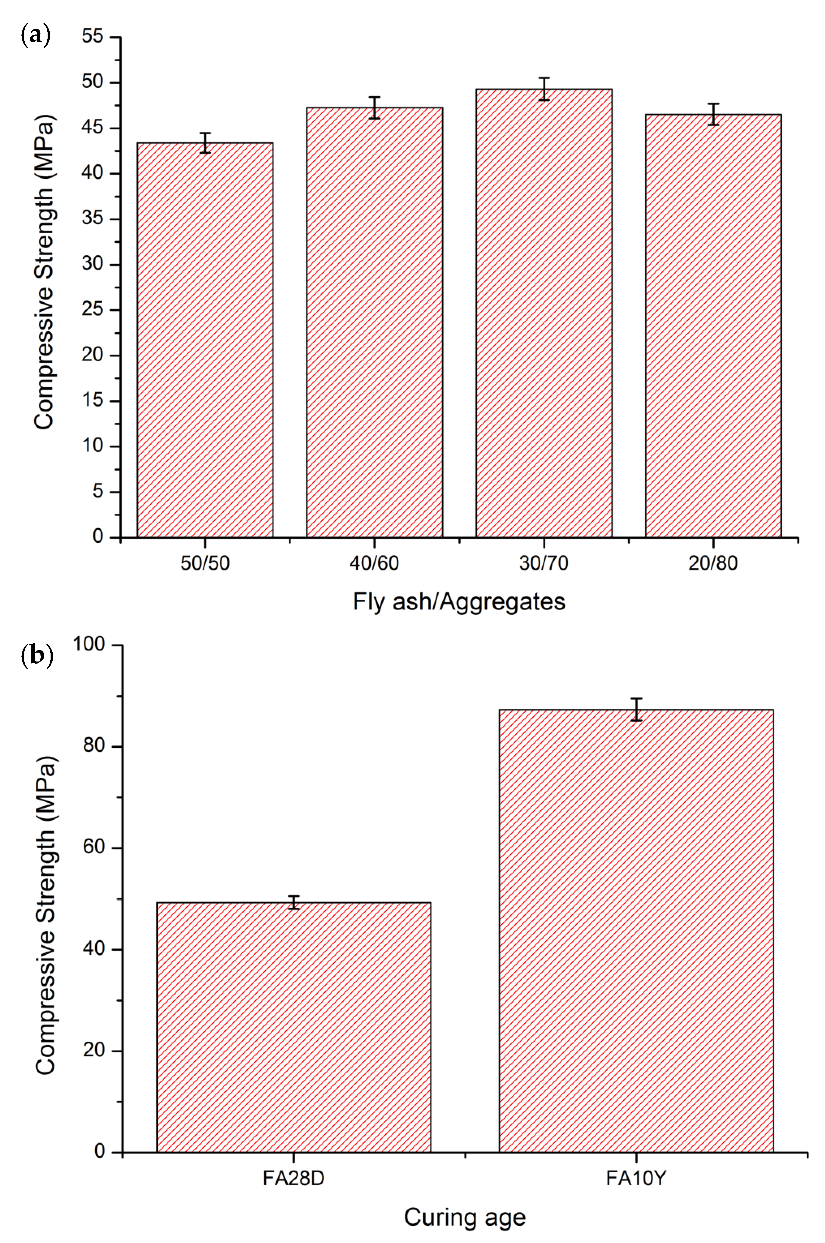
Figure 1. Compressive strength of fly ash geopolymer samples: (a) after 28 days curing at various fly ash/aggregates; and (b) at 28 days and 10 years of curing age.
Materials 16 01096 g001
Figure 2. SEM micrograph of fly ash geopolymer at different curing age; 28 days with various magnification: (a) 500×; (b) 1000×; (c) 5000×; and 10 years: (d) 500×; (e) 1000×; (f) 5000×.
Materials 16 01096 g002
Figure 3. The transformation of fly ash particle after 28 days and 10 years of curing age.
Materials 16 01096 g003
Figure 4. XRD diffractogram of fly ash geopolymer mortar at different curing age: (a) 28 days; and (b) 10 years.
Materials 16 01096 g004
Figure 5. Micro-XRF elemental distribution maps of Al, Si, Ca and Fe of fly ash geopolymer mortar at 28 days (ad) and 10 years (eh) curing age.
Materials 16 01096 g005
Figure 6. Various porosity size distribution at different curing age: (a) 28 days; and (b) 10 years of fly ash geopolymer.
Materials 16 01096 g006
Table 1. Chemical composition of Class C fly ash.
Elemental Oxide (wt%)
SiO2Al2O3CaOFe2O3TiO2MgOK2ONa2OP2O5LOI
26.49.2521.630.133.070.782.580.421.313.02
Disclaimer/Publisher’s Note: The statements, opinions and data contained in all publications are solely those of the individual author(s) and contributor(s) and not of MDPI and/or the editor(s). MDPI and/or the editor(s) disclaim responsibility for any injury to people or property resulting from any ideas, methods, instructions or products referred to in the content.