
High-Temperature, Lightweight Ceramics with Nano-Sized Ferrites for EMI Shielding: Synthesis, Characterisation, and Potential Applications
 , , ,
, , ,  ,
,  and
and 
Abstract
:1. Introduction
2. Materials and Methods
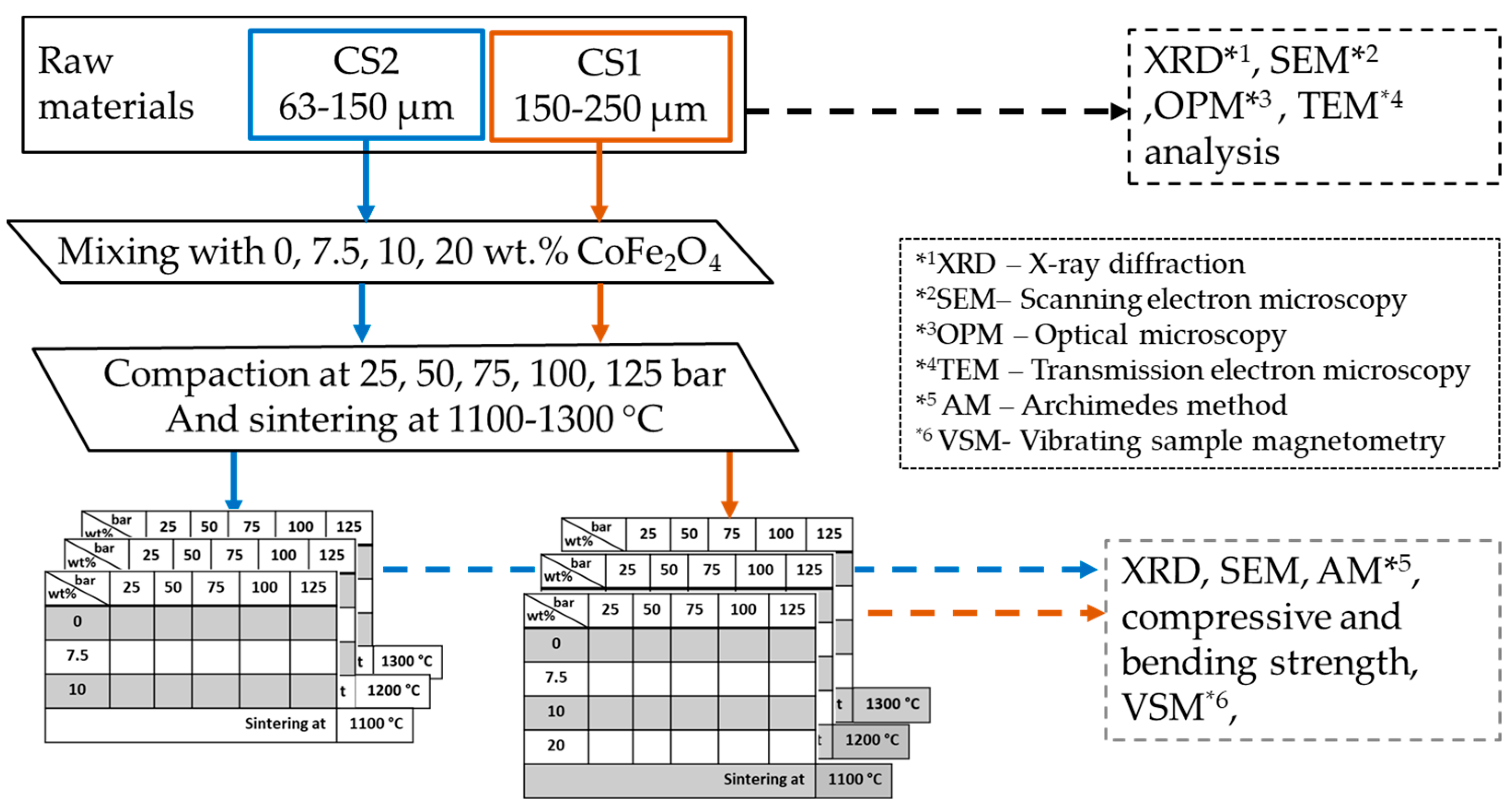
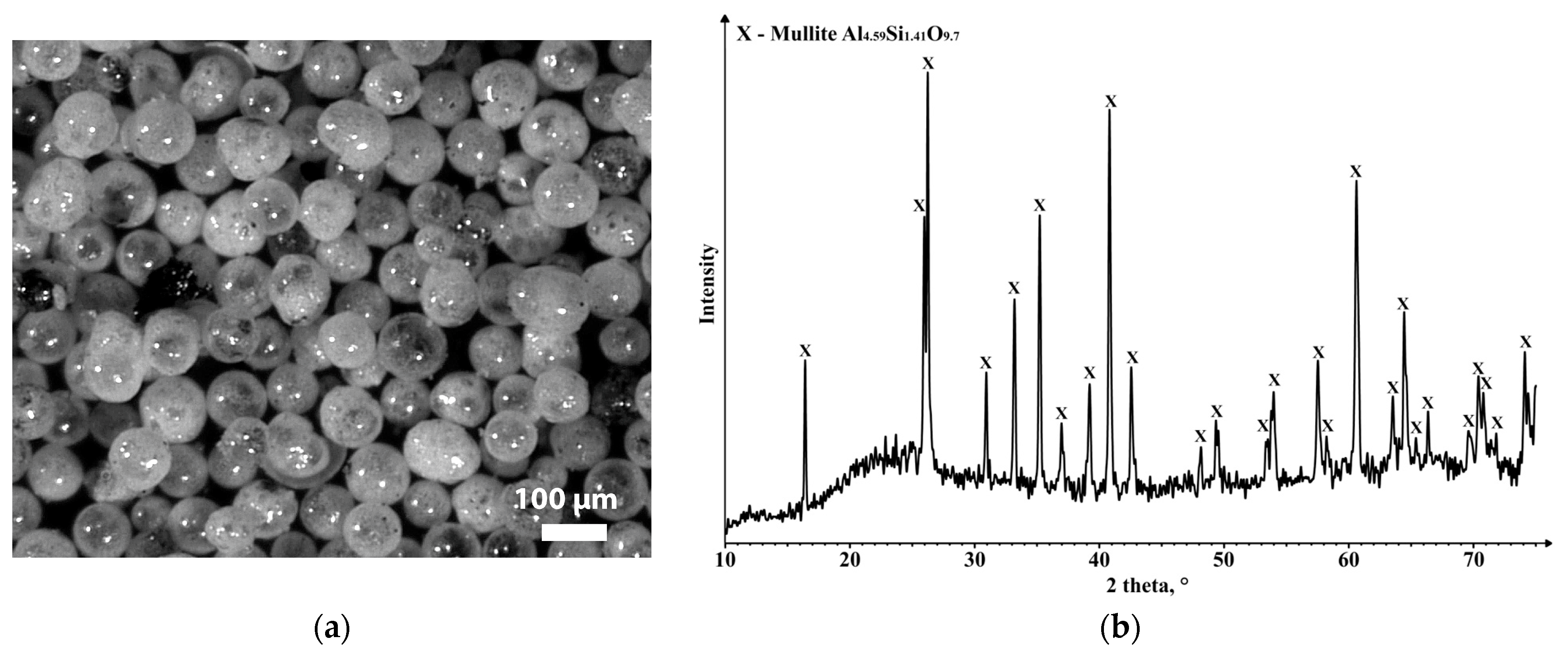
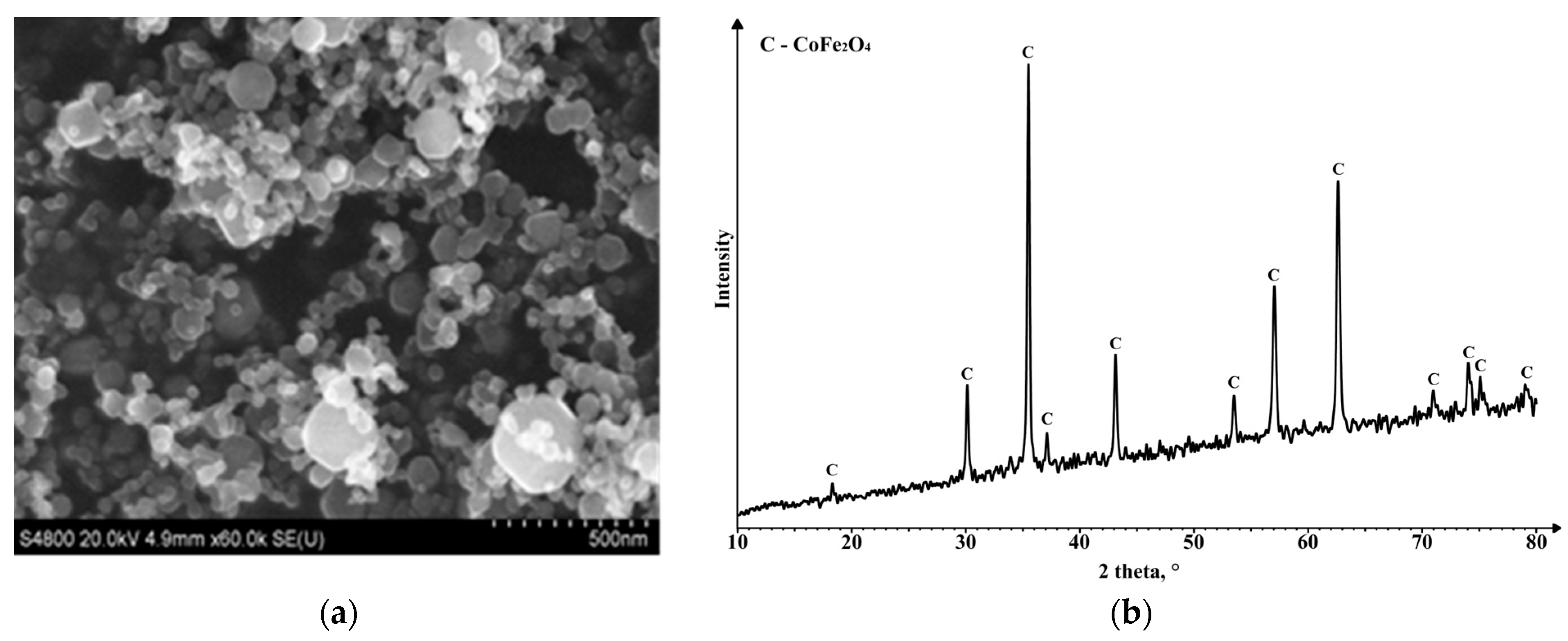
2.1. Materials
2.2. Sintering Process
2.3. Applied Characterization Methods
3. Results and Discussion
4. Conclusions
Author Contributions
Funding
Institutional Review Board Statement
Informed Consent Statement
Data Availability Statement
Conflicts of Interest
References
- Markham, D. Shielding: Quantifying the Shielding Requirements for Portable Electronic Design and Providing New Solutions by Using a Combination of Materials and Design. Mater. Des. 1999, 21, 45–50. [Google Scholar] [CrossRef]
- Lundgren, U.; Ekman, J.; Delsing, J. Shielding Effectiveness Data on Commercial Thermoplastic Materials. IEEE Trans. Electromagn. Compat. 2006, 48, 766–773. [Google Scholar] [CrossRef]
- Huang, J.-C. EMI Shielding Plastics: A Review. Adv. Polym. Technol. 1995, 14, 137–150. [Google Scholar] [CrossRef]
- Zhang, L.; Wang, L.B.; See, K.Y.; Ma, J. Effect of Carbon Nanofiber Reinforcement on Electromagnetic Interference Shielding Effectiveness of Syntactic Foam. J. Mater. Sci. 2013, 48, 7757–7763. [Google Scholar] [CrossRef]
- Ameli, A.; Jung, P.U.; Park, C.B. Through-Plane Electrical Conductivity of Injection-Molded Polypropylene/Carbon-Fiber Composite Foams. Compos. Sci. Technol. 2013, 76, 37–44. [Google Scholar] [CrossRef]
- Han, D.; Mei, H.; Xiao, S.; Xue, W.; Bai, Q.; Cheng, L. CNT/SiC Composites Produced by Direct Matrix Infiltration of Self-Assembled CNT Sponges. J. Mater. Sci. 2017, 52, 8401–8411. [Google Scholar] [CrossRef]
- Zhang, H.B.; Yan, Q.; Zheng, W.G.; He, Z.; Yu, Z.Z. Tough Graphene-Polymer Microcellular Foams for Electromagnetic Interference Shielding. ACS Appl. Mater. Interfaces 2011, 3, 918–924. [Google Scholar] [CrossRef]
- Xia, X.; Mazzeo, A.D.; Zhong, Z.; Weng, G.J. An X-Band Theory of Electromagnetic Interference Shielding for Graphene-Polymer Nanocomposites. J. Appl. Phys. 2017, 122, 025104. [Google Scholar] [CrossRef]
- Zhao, H.B.; Fu, Z.B.; Chen, H.B.; Zhong, M.L.; Wang, C.Y. Excellent Electromagnetic Absorption Capability of Ni/Carbon Based Conductive and Magnetic Foams Synthesized via a Green One Pot Route. ACS Appl. Mater. Interfaces 2016, 8, 1468–1477. [Google Scholar] [CrossRef]
- Zeng, Z.; Chen, M.; Pei, Y.; Seyed Shahabadi, S.I.; Che, B.; Wang, P.; Lu, X. Ultralight and Flexible Polyurethane/Silver Nanowire Nanocomposites with Unidirectional Pores for Highly Effective Electromagnetic Shielding. ACS Appl. Mater. Interfaces 2017, 9, 32211–32219. [Google Scholar] [CrossRef]
- Gupta, N.; Zeltmann, S.E.; Shunmugasamy, V.C.; Pinisetty, D. Applications of Polymer Matrix Syntactic Foams. JOM 2014, 66, 245–254. [Google Scholar] [CrossRef]
- Strzałkowska, E.; Adamczyk, Z. Influence of Chemical Composition of Fly-Ash Cenospheres on Their Grains Size. Int. J. Environ. Sci. Technol. 2020, 17, 809–818. [Google Scholar] [CrossRef]
- Choo, T.F.; Salleh, M.A.M.; Kok, K.Y.; Matori, K.A.; Rashid, S.A. Effect of Temperature on Morphology, Phase Transformations and Thermal Expansions of Coal Fly Ash Cenospheres. Crystals 2020, 10, 481. [Google Scholar] [CrossRef]
- Adesina, A. Sustainable Application of Cenospheres in Cementitious Materials–Overview of Performance. Dev. Built Environ. 2020, 4, 100029. [Google Scholar] [CrossRef]
- Shishkin, A.; Abramovskis, V.; Zalite, I.; Singh, A.K.; Mezinskis, G.; Popov, V.; Ozolins, J. Physical, Thermal, and Chemical Properties of Fly Ash Cenospheres Obtained from Different Sources. Materials 2023, 16, 2035. [Google Scholar] [CrossRef]
- Ranjbar, N.; Kuenzel, C. Cenospheres: A Review. Fuel 2017, 207, 1–12. [Google Scholar] [CrossRef]
- Baronins, J.; Setina, J.; Sahmenko, G.; Lagzdina, S.; Shishkin, A. Pore Distribution and Water Uptake in a Cenosphere-Cement Paste Composite Material. In Proceedings of the IOP Conference Series: Materials Science and Engineering, Riga, Latvia, 30 September–2 October 2015; Volume 96. [Google Scholar]
- Shishkin, A.; Drozdova, M.; Kozlov, V.; Hussainova, I.; Lehmhus, D. Vibration-Assisted Sputter Coating of Cenospheres: A New Approach for Realizing Cu-Based Metal Matrix Syntactic Foams. Metals 2017, 7, 16. [Google Scholar] [CrossRef]
- Luong, D.; Lehmhus, D.; Gupta, N.; Weise, J.; Bayoumi, M. Structure and Compressive Properties of Invar-Cenosphere Syntactic Foams. Materials 2016, 9, 115. [Google Scholar] [CrossRef]
- Kasar, A.K.; Gupta, N.; Rohatgi, P.K.; Menezes, P.L. A Brief Review of Fly Ash as Reinforcement for Composites with Improved Mechanical and Tribological Properties. JOM 2020, 72, 2340–2351. [Google Scholar] [CrossRef]
- Doddamani, M.; Gupta, N. 3D Printing of Fly Ash-Based Syntactic Foams. In Handbook of Fly Ash; Elsevier: Amsterdam, The Netherlands, 2021; pp. 739–818. [Google Scholar]
- Zalite, I.; Heidemane, G.; Grabis, J.; Maiorov, M. The Synthesis and Characterization of Nickel and Cobalt Ferrite Nanopowders Obtained by Different Methods. In Powder Technology; InTech: London, UK, 2018. [Google Scholar] [CrossRef]
- Sontu, U.B.; Yelasani, V.; Musugu, V.R.R. Structural, Electrical and Magnetic Characteristics of Nickel Substituted Cobalt Ferrite Nano Particles, Synthesized by Self Combustion Method. J. Magn. Magn. Mater. 2015, 374, 376–380. [Google Scholar] [CrossRef]
- Huixia, F.; Baiyi, C.; Deyi, Z.; Jianqiang, Z.; Lin, T. Preparation and Characterization of the Cobalt Ferrite Nano-Particles by Reverse Coprecipitation. J. Magn. Magn. Mater. 2014, 356, 68–72. [Google Scholar] [CrossRef]
- Kurtinaitiene, M.; Mazeika, K.; Ramanavicius, S.; Pakstas, V.; Jagminas, A. Effect of Additives on the Hydrothermal Synthesis of Manganese Ferrite Nanoparticles. Adv. Nano Res. 2016, 4, 1–14. [Google Scholar] [CrossRef]
- Jauhar, S.; Kaur, J.; Goyal, A.; Singhal, S. Tuning the Properties of Cobalt Ferrite: A Road towards Diverse Applications. RSC Adv. 2016, 6, 97694–97719. [Google Scholar] [CrossRef]
- Ramanavičius, S.; Žalnėravičius, R.; Niaura, G.; Drabavičius, A.; Jagminas, A. Shell-Dependent Antimicrobial Efficiency of Cobalt Ferrite Nanoparticles. Nano-Struct. Nano-Objects 2018, 15, 40–47. [Google Scholar] [CrossRef]
- Singh, A.K.; Shishkin, A.; Koppel, T.; Gupta, N. Porous Materials for EMI Shielding. In Materials for Potential EMI Shielding Applications; Elsevier: Amsterdam, The Netherlands, 2020; pp. 287–314. [Google Scholar]
- Sahu, S.; Mohapatra, P.P.; Karnajit Singh, H.; Dobbidi, P. Enhanced Microwave Absorbing Performance of Sr2+ Substituted Nickel-Cobalt Nano Ferrite for Radar and Stealth Applications. Mater. Sci. Eng. B 2023, 294, 116514. [Google Scholar] [CrossRef]
- Manobalan, S.; Bose, S.; Sumangala, T.P. Effect of Thickness on the EMI Shielding Effectiveness of Epoxy Composites with Cobalt Ferrite and Graphene. Mater. Today Proc. 2023, 90, 128–132. [Google Scholar] [CrossRef]
- Ai, J.; Shuai, Y.; Hu, M.; Cheng, L.; Luo, S.; Li, W.; Chen, Z.; Hu, L.; Zhou, Z. Microstructural Evolution and Catalytic Properties of Novel High-Entropy Spinel Ferrites MFe2O4 (M= Mg, Co, Ni, Cu, Zn). Ceram Int 2023, 49, 22941–22951. [Google Scholar] [CrossRef]
- Chakradhary, V.K.; Ansari, A.; Akhtar, M.J. Design, Synthesis, and Testing of High Coercivity Cobalt Doped Nickel Ferrite Nanoparticles for Magnetic Applications. J. Magn. Magn. Mater. 2019, 469, 674–680. [Google Scholar] [CrossRef]
- Gul, I.H.; Ahmed, W.; Maqsood, A. Electrical and Magnetic Characterization of Nanocrystalline Ni-Zn Ferrite Synthesis by Co-Precipitation Route. J. Magn. Magn. Mater. 2008, 320, 270–275. [Google Scholar] [CrossRef]
- Pubby, K.; Meena, S.S.; Yusuf, S.M.; Bindra Narang, S. Cobalt Substituted Nickel Ferrites via Pechini’s Sol–Gel Citrate Route: X-Band Electromagnetic Characterization. J. Magn. Magn. Mater. 2018, 466, 430–445. [Google Scholar] [CrossRef]
- Sagayaraj, R.; Aravazhi, S.; Chandrasekaran, G. Review on Structural and Magnetic Properties of (Co–Zn) Ferrite Nanoparticles. Int. Nano Lett. 2021, 11, 307–319. [Google Scholar] [CrossRef]
- Dippong, T.; Levei, E.A.; Cadar, O. Recent Advances in Synthesis and Applications of MFe2O4 (M = Co, Cu, Mn, Ni, Zn) Nanoparticles. Nanomaterials 2021, 11, 1560. [Google Scholar] [CrossRef]
- Wang, M.; Zhang, Y.; Dong, C.; Chen, G.; Guan, H. Preparation and Electromagnetic Shielding Effectiveness of Cobalt Ferrite Nanoparticles/Carbon Nanotubes Composites. Nanomater. Nanotechnol. 2019, 9, 1847980419837821. [Google Scholar] [CrossRef]
- Soleimani, H.; Yusuf, J.Y.; Chuan, L.K.; Soleimani, H.; bin Sabar, M.L.; Öchsner, A.; Abbas, Z.; Balogun, A.I.; Kozlowski, G. In-Situ Preparation of CoFe2O4 Nanoparticles on Eggshell Membrane-Activated Carbon for Microwave Absorption. Heliyon 2023, 9, e13256. [Google Scholar] [CrossRef]
- Molaei, S.; Ghadermazi, M. Copper-Decorated Core–Shell Structured Ordered Mesoporous Containing Cobalt Ferrite Nanoparticles as High-Performance Heterogeneous Catalyst toward Synthesis of Tetrazole. Sci. Rep. 2023, 13, 15146. [Google Scholar] [CrossRef]
- Lopez-Santiago, A.; Grant, H.R.; Gangopadhyay, P.; Voorakaranam, R.; Norwood, R.A.; Peyghambarian, N. Cobalt Ferrite Nanoparticles Polymer Composites Based All-Optical Magnetometer. Opt. Mater. Express 2012, 2, 978–986. [Google Scholar] [CrossRef]
- El-Masry, M.M.; Ramadan, R.; Ahmed, M.K. The Effect of Adding Cobalt Ferrite Nanoparticles on the Mechanical Properties of Epoxy Resin. Results Mater. 2020, 8, 100160. [Google Scholar] [CrossRef]
- Endrodi, B.; Hursán, D.; Petrilla, L.; Bencsik, G.; Visy, C.; Chams, A.; Maslah, N.; Perruchot, C.; Jouini, M. Incorporation of Cobalt-Ferrite Nanoparticles into a Conducting Polymer in Aqueous Micellar Medium: Strategy to Get Photocatalytic Composites. Acta Chim. Slov. 2014, 61, 376–381. [Google Scholar] [PubMed]
- Kumar, Y.; Sharma, A.; Shirage, P.M. Shape-Controlled CoFe2O4 Nanoparticles as an Excellent Material for Humidity Sensing. RSC Adv. 2017, 7, 55778–55785. [Google Scholar] [CrossRef]
- Nam, P.H.; Lu, L.T.; Linh, P.H.; Manh, D.H.; Thanh Tam, L.T.; Phuc, N.X.; Phong, P.T.; Lee, I.J. Polymer-Coated Cobalt Ferrite Nanoparticles: Synthesis, Characterization, and Toxicity for Hyperthermia Applications. New J. Chem. 2018, 42, 14530–14541. [Google Scholar] [CrossRef]
- Ramesh, S.; Patro, L.N.; Dhanalakshmi, B.; Chandrasekhar, B.; Babu, T.A.; Naidu, K.C.B.; Rao, B.P. Magnetic Properties of Mn/Co Substituted Nano and Bulk Ni–Zn Ferrites: A Comparative Study. Mater Chem Phys 2023, 306, 128055. [Google Scholar] [CrossRef]
- Caldeira, L.E.; Guaglianoni, W.C.; Venturini, J.; Arcaro, S.; Bergmann, C.P.; Bragança, S.R. Sintering-Dependent Mechanical and Magnetic Properties of Spinel Cobalt Ferrite (CoFe2O4) Ceramics Prepared via Sol-Gel Synthesis. Ceram. Int. 2020, 46, 2465–2472. [Google Scholar] [CrossRef]
- Zhou, J.; Tan, R.; Yao, Z.; Lin, H.; Li, Z. Preparation of CoFe2O4 Hollow Spheres with Carbon Sphere Templates and Their Wave Absorption Performance. Mater. Chem. Phys. 2020, 244, 122697. [Google Scholar] [CrossRef]
- Liu, Y.; Chen, Z.; Zhang, Y.; Feng, R.; Chen, X.; Xiong, C.; Dong, L. Broadband and Lightweight Microwave Absorber Constructed by in Situ Growth of Hierarchical CoFe2O4/Reduced Graphene Oxide Porous Nanocomposites. ACS Appl. Mater. Interfaces 2018, 10, 13860–13868. [Google Scholar] [CrossRef] [PubMed]
- Yadav, R.S.; Anju; Jamatia, T.; Kuřitka, I.; Vilčáková, J.; Škoda, D.; Urbánek, P.; Machovský, M.; Masař, M.; Urbánek, M.; et al. Excellent, Lightweight and Flexible Electromagnetic Interference Shielding Nanocomposites Based on Polypropylene with MnFe2O4 Spinel Ferrite Nanoparticles and Reduced Graphene Oxide. Nanomaterials 2020, 10, 2481. [Google Scholar] [CrossRef] [PubMed]
- Gao, Y.; Wang, Z. Microwave Absorption and Electromagnetic Interference Shielding Properties of Li-Zn Ferrite-Carbon Nanotubes Composite. J. Magn. Magn. Mater. 2021, 528, 167808. [Google Scholar] [CrossRef]
- Phan, C.H.; Mariatti, M.; Koh, Y.H. Electromagnetic Interference Shielding Performance of Epoxy Composites Filled with Multiwalled Carbon Nanotubes/Manganese Zinc Ferrite Hybrid Fillers. J. Magn. Magn. Mater. 2016, 401, 472–478. [Google Scholar] [CrossRef]
- Liu, H.Y.; Li, Y.S. Synthesis and Microwave Absorbing Properties of Cobalt Ferrite. In Proceedings of the IOP Conference Series: Materials Science and Engineering, Sanya, China, 18–20 November 2017; Volume 292. [Google Scholar]
- Zalite, I.; Heidemane, G.; Kodols, M.; Grabis, J.; Maiorov, M. The Synthesis, Characterization and Sintering of Nickel and Cobalt Ferrite Nanopowders. Medziagotyra 2012, 18, 3–7. [Google Scholar] [CrossRef]
- Zalite, I.; Heidemane, G.; Krumiņa, A.; Rašmane, D.; Grabis, J.; Maiorov, M. Characteristics of Sintered Materials Obtained from Ferrite Nanopowders Synthesised with Different Methods. Proc. Key Eng. Mater. 2018, 762, 257–262. [Google Scholar]
- Yim, Y.J.; Lee, J.J.; Tugirumubano, A.; Go, S.H.; Kim, H.G.; Kwac, L.K. Electromagnetic Interference Shielding Behavior of Magnetic Carbon Fibers Prepared by Electroless Feconi-Plating. Materials 2021, 14, 3774. [Google Scholar] [CrossRef]
- Liu, Q.; Zhang, Y.; Liu, Y.; Li, C.; Liu, Z.; Zhang, B.; Zhang, Q. Magnetic Field-Induced Strategy for Synergistic CI/Ti3C2Tx/PVDF Multilayer Structured Composite Films with Excellent Electromagnetic Interference Shielding Performance. J. Mater. Sci. Technol. 2022, 110, 246–259. [Google Scholar] [CrossRef]
- Ali, S.A.; Matin, M.A.; Hakim, M.A.; Islam, M.F. Effects of CoFe2O4 Substitution on Magnetic Properties of NiFe2O4 Spinel Ferrite. In Proceedings of the IOP Conference Series: Materials Science and Engineering, Dhaka, Bangladesh, 1–3 March 2018; Volume 438. [Google Scholar]
- Ashby, M. Material Property Charts. In Materials Selection in Mechanical Design, 4th ed.; Elsevier: Amsterdam, The Netherlands, 2011; pp. 57–96. [Google Scholar] [CrossRef]
- Liang, S.; Qin, Y.; Gao, W.; Wang, M. A Lightweight Polyurethane-Carbon Microsphere Composite Foam for Electromagnetic Shielding. E-Polymers 2022, 22, 223–233b. [Google Scholar] [CrossRef]
- Asandulesa, M.; Hamciuc, C.; Pui, A.; Virlan, C.; Lisa, G.; Barzic, A.I.; Oprisan, B. Cobalt Ferrite/Polyetherimide Composites as Thermally Stable Materials for Electromagnetic Interference Shielding Uses. Int. J. Mol. Sci. 2023, 24, 999. [Google Scholar] [CrossRef] [PubMed]
- Zhao, B.; Hamidinejad, M.; Wang, S.; Bai, P.; Che, R.; Zhang, R.; Park, C.B. Advances in Electromagnetic Shielding Properties of Composite Foams. J. Mater. Chem. A Mater. 2021, 9, 8896–8949. [Google Scholar] [CrossRef]
- Lehmhus, D.; Baumeister, J.; Stutz, L.; Schneider, E.; Stöbener, K.; Avalle, M.; Peroni, L.; Peroni, M. Mechanical Characterization of Particulate Aluminum Foams-Strain-Rate, Density and Matrix Alloy versus Adhesive Effects. Adv. Eng. Mater. 2010, 12, 596–603. [Google Scholar] [CrossRef]
- Akinwekomi, A.D.; Tang, C.Y.; Tsui, G.C.P.; Law, W.C.; Chen, L.; Yang, X.S.; Hamdi, M. Synthesis and Characterisation of Floatable Magnesium Alloy Syntactic Foams with Hybridised Cell Morphology. Mater. Des. 2018, 160, 591–600. [Google Scholar] [CrossRef]
- Orbulov, I.N.; Ginsztler, J. Compressive Characteristics of Metal Matrix Syntactic Foams. Compos. Part A Appl. Sci. Manuf. 2012, 43, 553–561. [Google Scholar] [CrossRef]
- Tang, D.; Yang, K.; Gao, T.; Liu, T.; Tang, H. Mechanical-Electromagnetic Integration Design of Al2O3/SiO2 Ceramic Cellular Materials Fabricated by Digital Light Processing. Thin-Walled Struct. 2023, 183, 110437. [Google Scholar] [CrossRef]
- Yin, S.; Jiang, Y.; Su, K.; Fang, X.; Wang, Y.; Li, Q.; Yang, J. Preparation, Mechanical, Dielectric and Microwave Absorption Properties of Hierarchical Porous SiCnw-Si3N4 Composite Ceramics. J. Eur. Ceram. Soc. 2022, 42, 3820–3830. [Google Scholar] [CrossRef]
- Shorstkii, I.; Sosnin, M. Microwave Absorption Properties of Fe3O4 Particles Coated with al via Rotating Magnetic Field Method. Coatings 2021, 11, 621. [Google Scholar] [CrossRef]


| Ferrite | Magnetic Properties | ||
|---|---|---|---|
| Ms, emu/g | Mr, emu/g | Hc, Oe | |
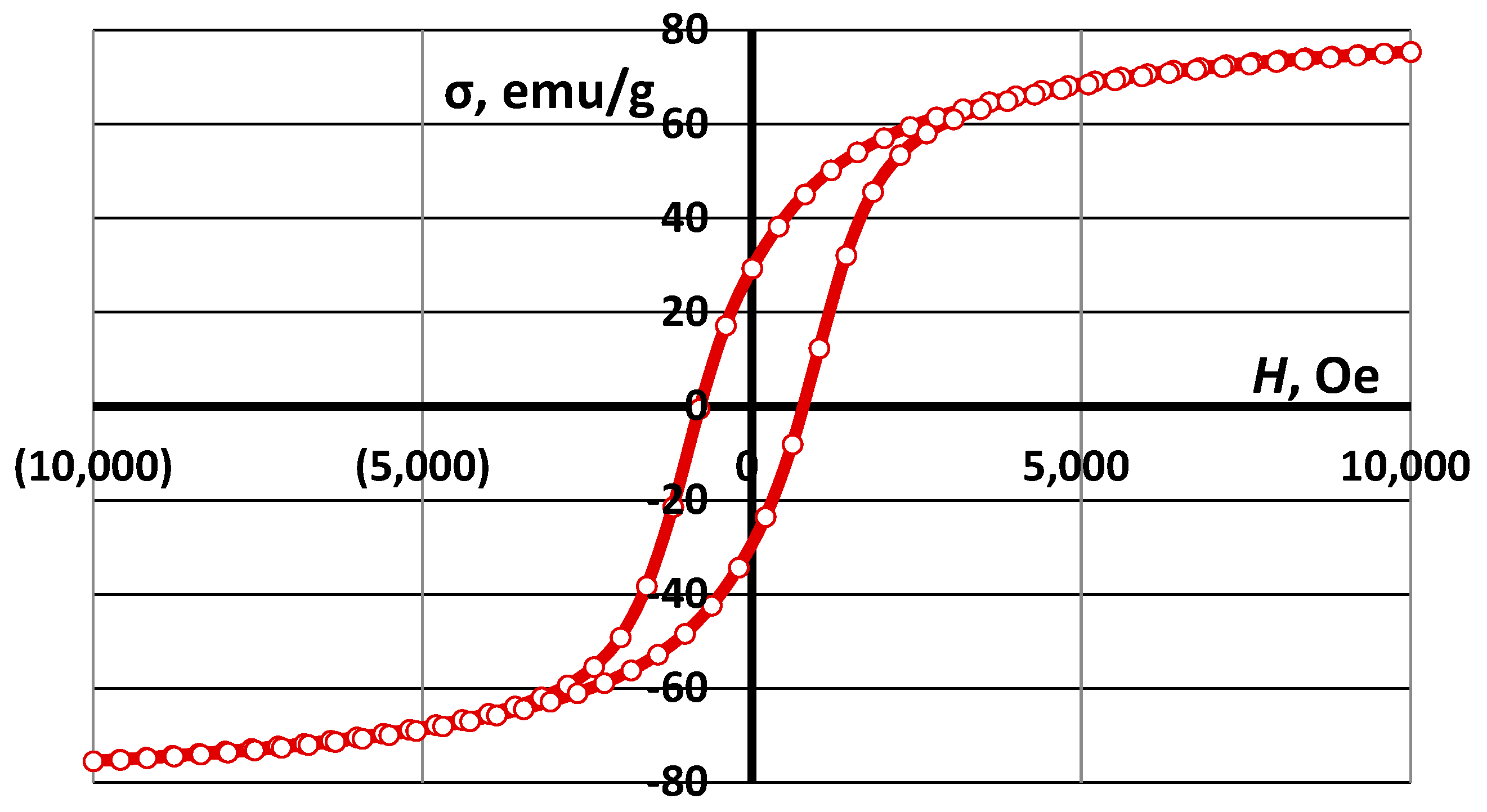
| CoFe2O4 | 75.4 | 32.0 | 780 |
| Sample | Density, g·cm–3 (%) | Water Absorption (W), % | Apparent Porosity (π), % | Compressive Strength (σcomp.), MPa | Bending Strength (σbend.), MPa | Flexural Modulus, MPa | Deformation (ε), % |
|---|---|---|---|---|---|---|---|
| CS1-0 | 1.03 (32.2) | 50.7 | 52.0 | 12.4 ± 0.1 | 7.1 ± 0.4 | 1960 ± 180 | 0.39 |
| CS1-7.5 | 1.17 (35.0) | 45.9 | 49.9 | 29.3 ± 2.8 | 10.2 ± 0.3 | 5190 ± 130 | 0.41 |
| CS1-10 | 1.31 (38.4) | 33.7 | 44.2 | 47.4 ± 12.6 | 17.9 ± 1.6 | 4830 ± 450 | 0.52 |
| CS2-0 | 1.05 (32.8) | 48.8 | 51.3 | 17.4 ± 5.8 | 6.0 ± 0.4 | 2690 ± 310 | 0.21 |
| CS2-10 | 1.32 (38.9) | 34.2 | 45.1 | 41.7 ± 6.2 | 12.3 ± 1.9 | 5220 ± 490 | 0.23 |
| Sample | Magnetic Properties | ||
|---|---|---|---|
| Ms, emu/g | Mr, emu/g | Hc, Oe | |
| CS2-7.5 wt.% CoFe2O4 | 1.17 | 0.47 | 375 |
| CS1-7.5 wt.% CoFe2O4 | 2.04 | 0.65 | 275 |
| CS1-10 wt.% CoFe2O4 | 2.78 | 1.00 | 275 |
| CS1-20 wt.% CoFe2O4 | 6.93 | 2.30 | 275 |
| Material Type | Density (g·cm–3) | Compression Strength (MPa) | Band (GHz), EMI SE (dB), or Other | Ref. |
|---|---|---|---|---|
| Polymer/organic materials | ||||
| CNT + mesoporous carbon micro HS + water-based PU + polyvinyl alcohol | 0.23–0.26 | 3 | Band 8–12 GHz EMI SE 28 dB | [59] |
| CoFe2O4/Polyetherimide composites | N/A | N/A | Saturation and remanent magnetization values are from 4.39 to 27.9 and 1.47–9.57 emu·g−1 | [60] |
| Carbon foams | ||||
| Ag@C-1000 | 0.00382 | N/A | Band 8.2–12.4 GHz EMI SE 70.1 dB | [61] |
| Cu/large flake size graphene film | N/A | Band 1–2 GHz EMI SE 61.39–63.29 dB | [61] | |
| CuNW@G core–shell aerogels | 0.165 | N/A | Band 8–18 GHz EMI SE 52.5 dB | [61] |
| Carbon/MnO2 foam | N/A | Band 8.2–12.4 GHz EMI SE 50 dB | [61] | |
| Carbon/GO/SiO2 | N/A | Band 8.2–12.4 GHz EMI SE 24 dB | [61] | |
| Metals and alloy composites | ||||
| Al foams | 0.35 to 0.71 | 17.5 | N/A | [62] |
| AlSi7 foams | 0.35 and 0.66 | N/A | [62] | |
| AZ61-CS | 0.9–1.1 | 16–30 | N/A | [63] |
| AZ61 with spherical carbamide granules | 0.79–1.02 | 16–28 | N/A | [64] |
| Al99.5–SL150 with ceramic microballoons | 1.43 | 169 | N/A | [64] |
| Al99.5–SL300 | 1.52 | 154 | N/A | [64] |
| AlSi12–SL300 | 1.37 | 176 | N/A | [6] |
| Opened-cell porous aluminium foam | N/A | N/A | Band 1–8 GHz EMI SE 40–70 dB | [61] |
| Aluminium foam | N/A | N/A | Band 130–1800 MHz EMI SE 2575 dB | [61] |
| CNTs/Cu foams | N/A | N/A | Band 8.2–12.4 GHz EMI SE 33.63 dB | [61] |
| Ceramics | ||||
| Al2O3/SiO2 | N/A | 24 | Band 2–18 GHz EMI SE–55 dB | [65] |
| Hierarchical porous SiC-NW-Si3N4 | Bulk density 1.61–1.92 | 142.19–240.36 | Good microwave absorption properties | [66] |
| Fe3O4 particles coated with Al | N/A | N/A | Band 5–13 GHz EMI SE from −16.2 to −12.5 dB | [67] |
| Cu–Ni–CNT foam | 0.24 | N/A | Band 8–12 GHz EMI SE 47.5 dB | [61] |
| This research | ||||
| CS–CoFe2O4 * 7.5 wt.%, sintered 1100 °C | 1.33–1.65 | 40–65 | Saturation and remanent magnetization values are from 2.04 emu·g−1 | --- |
| CS–CoFe2O4 * 7.5 wt.%, sintered 1200 °C | 1.35–1.67 | 27–44 | Saturation and remanent magnetization values are 1.17 emu·g−1 | --- |
| CS–CoFe2O4 * 20.0 wt.%, sintered 1200 °C | 1.54–1.9 | 58–98 | Saturation and remanent magnetization values are 6.93 emu·g−1 | --- |
| CS–CoFe2O4 * 7.5 wt.%, sintered 1300 °C | 1.59–1.98 | 76–106 | Saturation and remanent magnetization values are from 2.04 emu·g−1 | --- |
Disclaimer/Publisher’s Note: The statements, opinions and data contained in all publications are solely those of the individual author(s) and contributor(s) and not of MDPI and/or the editor(s). MDPI and/or the editor(s) disclaim responsibility for any injury to people or property resulting from any ideas, methods, instructions or products referred to in the content. |
© 2023 by the authors. Licensee MDPI, Basel, Switzerland. This article is an open access article distributed under the terms and conditions of the Creative Commons Attribution (CC BY) license (https://creativecommons.org/licenses/by/4.0/).
Share and Cite
Abramovskis, V.; Zalite, I.; Maiorov, M.; Baronins, J.; Singh, A.K.; Lapkovskis, V.; Goel, S.; Shishkin, A. High-Temperature, Lightweight Ceramics with Nano-Sized Ferrites for EMI Shielding: Synthesis, Characterisation, and Potential Applications. Materials 2023, 16, 7615. https://doi.org/10.3390/ma16247615
Abramovskis V, Zalite I, Maiorov M, Baronins J, Singh AK, Lapkovskis V, Goel S, Shishkin A. High-Temperature, Lightweight Ceramics with Nano-Sized Ferrites for EMI Shielding: Synthesis, Characterisation, and Potential Applications. Materials. 2023; 16(24):7615. https://doi.org/10.3390/ma16247615
Chicago/Turabian StyleAbramovskis, Vitalijs, Ilmars Zalite, Mikhail Maiorov, Janis Baronins, Ashish Kumar Singh, Vjaceslavs Lapkovskis, Saurav Goel, and Andrei Shishkin. 2023. "High-Temperature, Lightweight Ceramics with Nano-Sized Ferrites for EMI Shielding: Synthesis, Characterisation, and Potential Applications" Materials 16, no. 24: 7615. https://doi.org/10.3390/ma16247615
APA StyleAbramovskis, V., Zalite, I., Maiorov, M., Baronins, J., Singh, A. K., Lapkovskis, V., Goel, S., & Shishkin, A. (2023). High-Temperature, Lightweight Ceramics with Nano-Sized Ferrites for EMI Shielding: Synthesis, Characterisation, and Potential Applications. Materials, 16(24), 7615. https://doi.org/10.3390/ma16247615