Article

Characterization of SiO2 Plasma Etching with Perfluorocarbon (C4F8 and C6F6) and Hydrofluorocarbon (CHF3 and C4H2F6) Precursors for the Greenhouse Gas Emissions Reduction

1
Department of Physics, Chungnam National University, Daejeon 34134, Republic of Korea
2
Institute of Quantum Systems (IQS), Chungnam National University, Daejeon 34134, Republic of Korea
3
Department of Advanced Materials Science and Engineering, Sungkyunkwan University, Suwon 16419, Republic of Korea
4
SKKU Advanced Institute of Nano Technology (SAINT), Sungkyunkwan University, Suwon 16419, Republic of Korea
*
Author to whom correspondence should be addressed.
Materials 2023, 16(16), 5624; https://doi.org/10.3390/ma16165624
Submission received: 26 June 2023 / Revised: 9 August 2023 / Accepted: 13 August 2023 / Published: 14 August 2023
(This article belongs to the Section Manufacturing Processes and Systems)

Abstract

:
This paper proposes the use of environmentally friendly alternatives, C6F6 and C4H2F6, as perfluorocarbon (PFC) and hydrofluorocarbon (HFC) precursors, respectively, for SiO2 plasma etching, instead of conventional precursors C4F8 and CHF3. The study employs scanning electron microscopy for etch profile analysis and quadrupole mass spectrometry for plasma diagnosis. Ion bombardment energy at the etching conditions is determined through self-bias voltage measurements, while densities of radical species are obtained using quadrupole mass spectroscopy. The obtained results compare the etch performance, including etch rate and selectivity, between C4F8 and C6F6, as well as between CHF3 and C4H2F6. Furthermore, greenhouse gas (GHG) emissions are evaluated using a million metric ton of carbon dioxide equivalent, indicating significantly lower emissions when replacing conventional precursors with the proposed alternatives. The results suggest that a significant GHG emissions reduction can be achieved from the investigated alternatives without a deterioration in SiO2 etching characteristics. This research contributes to the development of alternative precursors for reducing global warming impacts.

1. Introduction

The semiconductor industry has extensively embraced plasma technology for semiconductor device manufacturing [1,2]. In the etching process, plasma has become crucial for nanoscale material processing, enabling precise and deep etch profiles to meet the requirements of scaling down of transistor feature sizes [3]. As a results, plasma processing has become indispensable for the production of next-generation semiconductor devices, including high-aspect-ratio contact (HARC) hole.
Plasma etching utilizes various gases or gas mixture tailored to the target materials, such as semiconductors [4,5], metals [6,7,8], and dielectrics [9,10,11,12]. For dielectrics, such as SiO2 and Si3N4, fluorocarbon-based molecules, such as C4F8 and CHF3, are widely adopted due to their polymerizing properties, which are particularly advantageous for achieving anisotropic etch profiles. During the etching process, fluorocarbon films passivate the sidewalls of the dielectric trench, preventing them from reacting with reactive etchants. However, the energetic plasma ion bombardment renders the fluorocarbon film unable to protect the trench bottom, resulting in an anisotropic etch profile [13,14,15]. Since anisotropy is a crucial characteristic in semiconductor manufacturing, large quantities of perfluorocarbon (PFC) and hydrofluorocarbon (HFC) precursors, such as C4F8 and CHF3, are extensively utilized in the semiconductor industry.
However, the utilization of the PFC and HFC precursors is subject to strict regulations due to their significant greenhouse effect [16,17]. Global warming potential (GWP) is a metric used to quantify the relative warming impact of greenhouse gases (GHGs) on the Earth’s climate system over a specified time horizon, typically, 20, 100, or 500 years, relatively to that of CO2 [18]. The GWP100 (GWP over a 100-year time horizon) of C4F8 and CHF3 is reported as 9540 and 12,400, respectively, indicating that these precursors have a greenhouse effect over 10,000 times stronger than CO2 [19]. Given the substantial global efforts to combat global warming in recent decades [20,21], the emission of these high-GWP gases is facing increasingly stringent restrictions in the industry [22].
In this context, researchers worldwide have been actively engaged in developing alternative plasma etching precursors that process low GWPs while demonstrating comparable etch performance to conventional ones. Sung et al. investigated the etching characteristics of SiO2 using the C6F6/Ar/O2 gas mixture in both capacitively coupled and inductively coupled plasma etching systems, comparing the etch results obtained from these different plasma systems [23]. Kim et al. studied SiO2 etching using C4H3F7O isomers and compared them with C4F8 through X-ray photoelectron spectroscopy, quadrupole mass spectroscopy, and scanning electron microscopy [24]. Furthermore, Lim et al. compared the etch results with a low-GWP precursor, C6F12O, to those with the conventional precursor, CF4 [25]. Although many papers, including the aforementioned ones, have documented the development of alternative low-GWP precursors in the field of semiconductor manufacturing [26,27,28,29,30], there are still numerous potential precursors that need to be investigated regarding their qualification as promising alternatives to conventional high-GPW precursors.
In this work, we propose the use of environmentally friendly alternatives, C6F6 and C4H2F6, as PFC and HFC precursors, respectively, for SiO2 plasma etching, in lieu of the conventional precursors C4F8 and CHF3, which are the most representative etching gases for dielectric etching [3]. C4F8 and CHF3 are selected as the reference precursors for PFC and HFC precursors, respectively, instead of other alternative low-GWP precursors, such as C4F6 (GWP < 1), to excavate additional alternatives that possibly show different etching performance from C4F6, which would provide a wide range of options to, for example, process engineers. Among various candidates as an alternative low-GWP precursor, the investigation into C6F6 and C4H2F6 is reported here. It should also be noted that CHF3, an H-containing fluorocarbon precursor, is normally used for nitride etching. To the best of our knowledge, more than one material are etched simultaneously in an etching process and specifically in dielectric etching, etching selectivity of nitride-to-oxide or vice versa is essential. We thus consider that evaluating the etching performance of HFC precursors, such as CHF3, on SiO2 is quite necessary. Additionally, we also consider that an HFC precursor should be compared with another HFC precursor, not a perfluorocarbon precursor like C4F8, to reduce any complexity that might be induced by H atoms included in HFC precursors but not in PFC ones. A low-GWP candidate, C4H2F6, was therefore compared with CHF3 to determine whether C4H2F6 was appropriate as an alternative to CHF3 or not.
We employ scanning electron microscopy and plasma diagnostics to analyze the etching results. Ion bombardment energy is determined by measuring self-bias voltages, while densities of various radical species are obtained through quadrupole mass spectroscopy. The obtained results include a comprehensive comparison of the etch performance, encompassing etch rate and selectivity, between C4F8 and C6F6, as well as between CHF3 and C4H2F6. Furthermore, we evaluate the greenhouse gas emissions using a million metric tons of carbon dioxide equivalent, which demonstrates significantly lower emissions when substituting conventional precursors with the proposed alternatives. The experimental setup and procedure details are provided in the subsequent sections.

2. Experiment

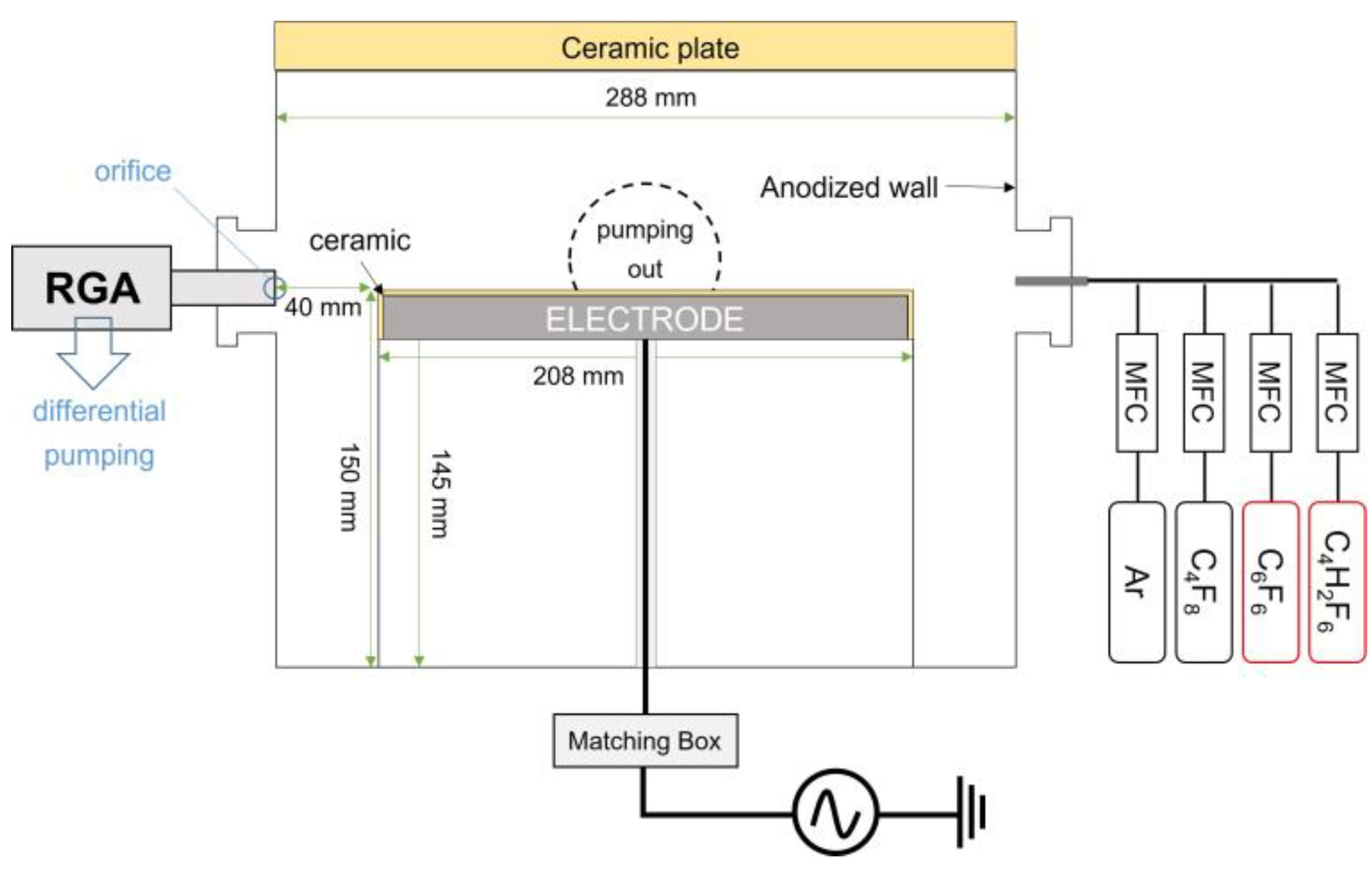
2.1. Processing Chamber Setup

The schematic diagram of the plasma chamber used for SiO2 etching is presented in Figure 1. Radiofrequency (RF) power of 13.56 MHz is applied to the electrode, which has a diameter of 208 mm covered with a 2 mm-thick ceramic plate, through an impedance matching box. While being injected into the chamber via a 1/4” SUS tube, the flow rate of Ar is controlled by a mass flow rate controller (MFC) (1179A611522K, MKS Instruments Inc., Andover, MA, USA) and that of PFC and HFC precursors is controlled by the different model of an MFC (M3030VA, Line-Tech, Daejeon, Republic of Korea). The investigated PFC precursors are octafluorocyclobutane (C4F8) and hexafluorobenzene (C6F6), while the investigated HFC precursors are trifluoromethane (CHF3) and hexafluoro-isobutylene (C4H2F6). The specific material information on the investigated precursors is summarized in Table 1.
The flow rate of Ar and a fluorocarbon precursor are fixed at 20 sccm and 10 sccm, respectively. It should be noted that the canisters containing C6F6 and C4H2F6 are heated to 130   ° C in order to vaporize them, and are in the liquid phase at room temperature. The RF power applied ranges from 300 W to 500 W and the pressure varies from 10 mTorr to 30 mTorr (Table 2). When the RF power varies, the pressure is regulated by a throttle valve; when the pressure changes, the RF power is fixed at 400 W. The chamber is evacuated by a turbomolecular pump, with an oil rotary pump serving as a backing pump, to achieve a base pressure below 10−4 Torr.

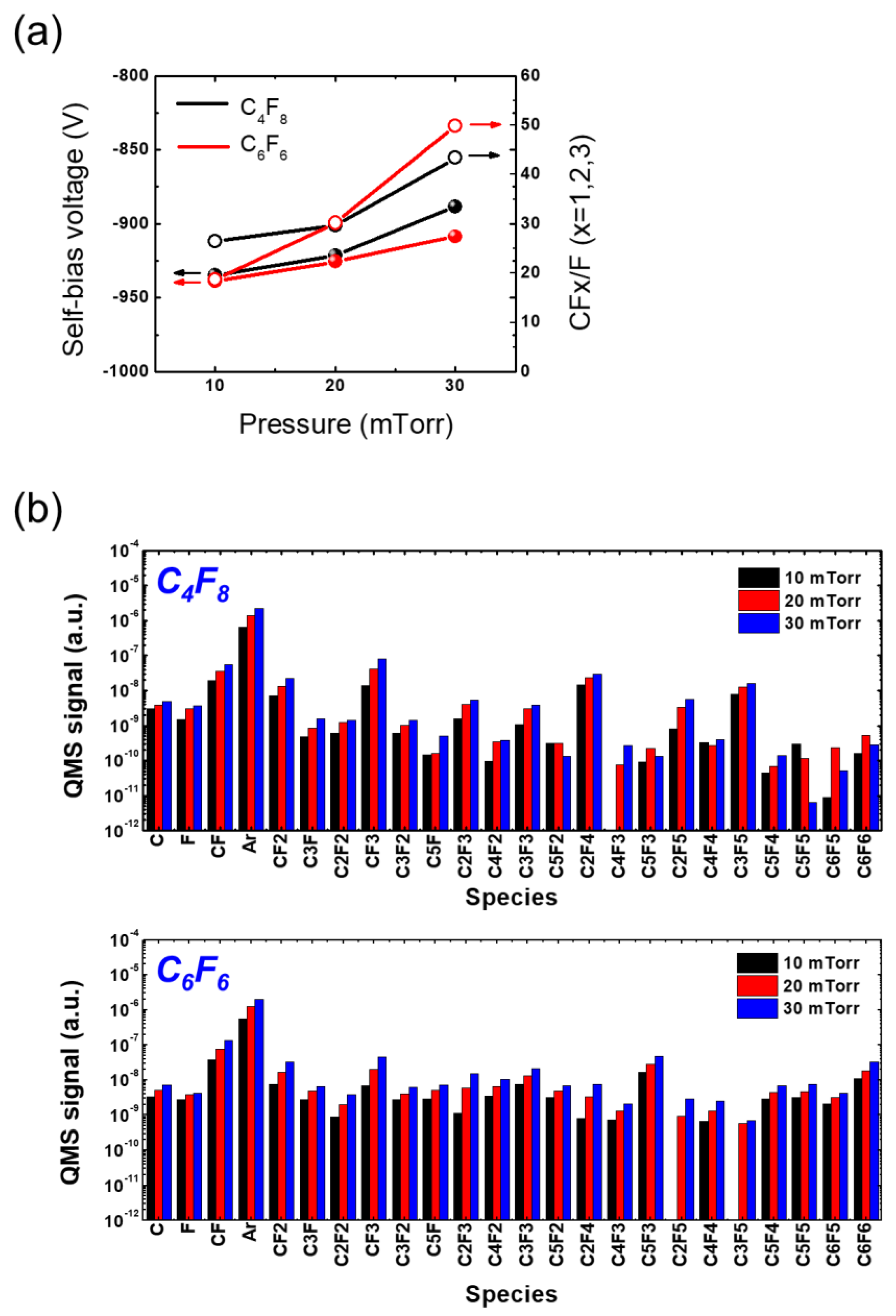
2.2. Plasma Diagnosis

We utilized a high-voltage (HV) probe (P5100, Tektronix, Inc., Beaverton, OR, USA) and a residual gas analyzer (RGA) (SRS-200, Stanford Research Systems, Sunnyvale, CA, USA) to analyze the SiO2 etching results obtained with different precursors. The HV probe is connected to the transmission line responsible for RF input power positioned between the electrode and the matching box. This measures the self-bias voltage of the electrode, providing an estimation of the ion bombarding energy during plasma processing [32]. RGAs are widely employed plasma diagnostics tools that offer information about gas-phase species in plasmas [33,34,35,36]. With an RGA, gas-phase atoms or molecules ionized by the collision with 70 eV energetic electrons and then filtered based on their mass as they pass through a quadrupole mass filter operating in a cross-linked manner [37]. This filtering process enables the RGA to generate a signal intensity profile as a function of atomic mass [38]. The RGA, located on a chamber port, has a separate vacuum space from the main chamber via an orifice with the diameter of approximately 100 μ m , which helps in maintaining the RGA pressure at approximately two orders of magnitude lower than the main chamber pressure [39]. The orifice is considered to directly contact to the plasma diagnosed as the chamber wall. This dedicated vacuum system allows gas-phase atoms and molecules to traverse the RGA without experiencing collisions with background gas, thereby increasing data reliability.
It should be noted that the impact of electrons of 70 eV would result in a measurement error from the dissociative ionization reaction of a parent molecule [40]; specifically, if C4F8 collides with 70 eV electrons, CF2+ ions can be generated and they are almost indistinguishable from the CF2+ ions generated in plasma in QMS analysis. Reducing the noise from dissociative ionization will be addressed in future work.

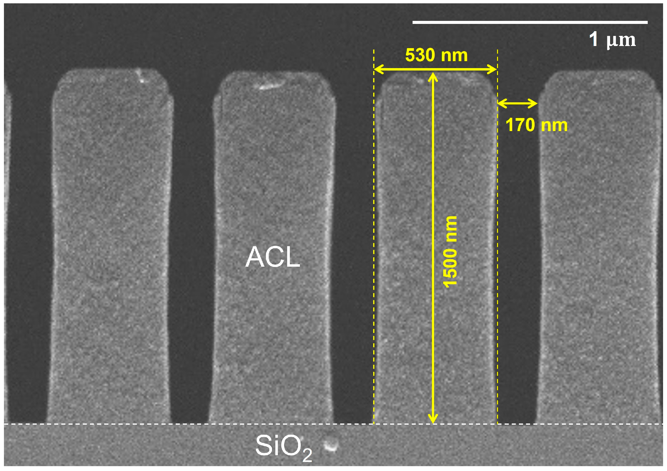
2.3. Sample Preparation

We prepared SiO2 coupon wafers with a masking layer of amorphous carbon (ACL) that has bar-type deep-trench patterns. Figure 2 presents the cross-sectional view of the mask pattern before etching with a width of 170 nm, a depth of 1500 nm, and a pitch of 530 nm. This cross-sectional image of the not-etched SiO2 sample serves as a reference for comparing the images of the samples after etching. All the images presented in this paper were acquired using a scanning electron microscope (SEM) (SU7000, Hitachi, Ltd., Tokyo, Japan).

3. Results and Discussion

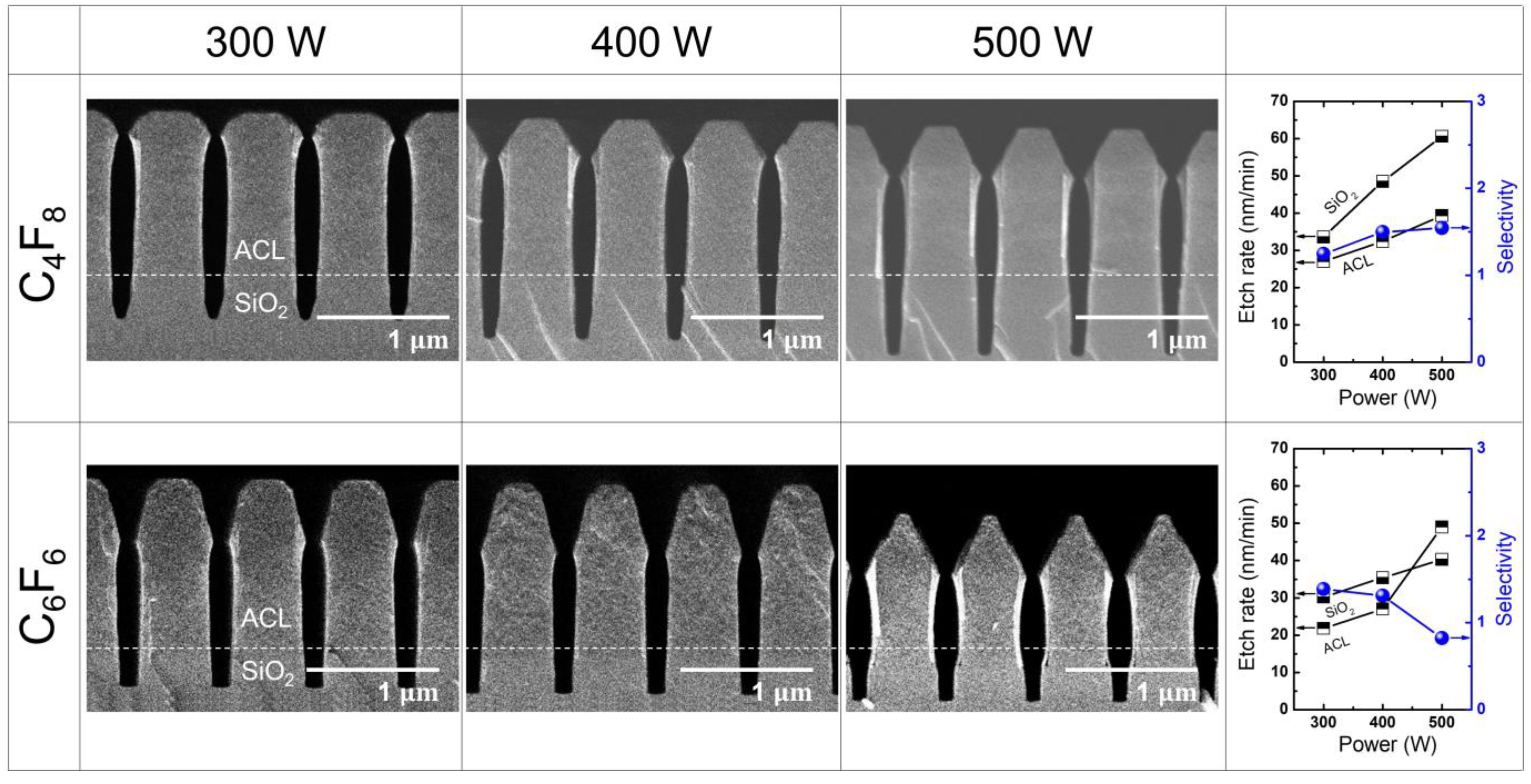
3.1. SiO2 Etching with PFC Precursors (C4F8 and C6F6)

Figure 3 illustrates the etch results obtained with different PFC precursors (C4F8 and C6F6) at varying RF power levels ranging from 300 W to 500 W, while maintaining a fixed pressure of 20 mTorr. The resulting etch rates and selectivity for the C4F8 and C6F6 cases are summarized in the right-most column of Figure 3. The etch rate of ACL is calculated by measuring the difference between the lengths from the ACL-SiO2 border line to the top surface of ACL before and after etching, divided by the etching duration of 10 min. Similarly, the etch rate of SiO2 is determined by dividing the etch depth, defined as the length between the border line and the minimum position of the etched SiO2 trenches, by the etching duration of 10 min. The etch selectivity is then obtained by dividing the SiO2 etch rate by the ACL etch rate.
Regarding the SiO2 etch rate, there is no significant difference observed between C4F8 and C6F6, although the difference becomes more pronounced with increasing RF power. It is noteworthy that, despite the significantly higher GWP100 of C4F8 (9540) compared with C6F6 (7) by over 1000 times [23], the similar etch rate implies that adopting the low-GWP alternative precursor can result in a substantial reduction in the greenhouse effect without compromising etch throughput.
As depicted in Figure 3, it can be observed that the SiO2 and ACL etch rates with C4F8 increase almost linearly with increasing RF power, leading to a nearly constant selectivity. On the other hand, with C6F6, it is notable that the ACL etch rate abruptly increases with increasing RF power while the SiO2 etch rate shows a slight linear increase. Consequently, this rapid increase in ACL etch rate causes the selectivity to drop below 1. Such low selectivity with C6F6 can be attributed to the mask faceting, which worsens with higher RF power. Comparing the etch profiles obtained with C4F8 and C6F6, it is evident that mask faceting is more pronounced with C6F6 than with C4F8. For both C4F8 and C6F6 cases, it is commonly observed that, as RF power increases, mask faceting tends to deteriorate. This deterioration results in bowing of the mask, referring to a concave etch profile caused by the lateral, as well as vertical etching of the trench sidewall due to ion bombardment on the facet [3]. According to material sputtering theory, the sputtering yield is highest at incident angles ranging from 40° to 60°, rather than 90° [41]. This behavior is clearly reflected in the etch results shown in Figure 3. Comparing the transition of mask height and faceting, it is observed that, while the mask height barely changes, the mask faceting evolves rapidly with increasing RF power. Mask faceting induces mask bowing, which eventually affects the SiO2 etch profile as the concave mask profile expands across the mask-SiO2 border. Such mask faceting occurs more intensely with C6F6 than with C4F8, as presented in Figure 3. Notably, an increase in RF power from 400 W to 500 W resulted in a significant rise in the mask etch rate. This could be attributed to the left and right mask facets meeting during etching, forming a spear-like mask head. As discussed earlier, ion bombardment is more effective on a tilted surface compared with a flat surface, and thus the spear-like mask head created by the joint of the left and right facets could lead to the rapid mask etching.
To analyze the differences in etching behavior between C4F8 and C6F6 precursors, we investigated changes in ion bombardment energy and radical density. In a capacitively coupled plasma etching system, such as the one used in this work, where the samples are loaded on the bottom electrode, also as in this work, the powered electrode (bottom electrode) voltage primarily consists of a negative DC component that accelerates the bombarding ions, allowing them to reach even the bottom of deep trenches [41]. Therefore, it is crucial to measure the self-bias voltage of the powered electrode to determine the ion bombardment energy under specific plasma conditions. We employed a high-voltage probe to measure the self-bias voltage on the powered electrode.
Figure 4a shows the measured self-bias voltage (left y-axis) and the CFx/F (x = 1, 2, 3) ratio (right y-axis) as a function of applied RF power using C4F8 and C6F6. The CFx/F ratios are calculated by using the FC radical signals represented in Figure 4b where CFx refers to the sum of the CF, CF2, and CF3 signal and is divided by the F signal at different RF power conditions. Note that the parameter, a CFx/F ratio, is adopted to interpret the chaotic contribution of numerous radical species to etch results in a simple manner. More detailed analysis of the measured radical densities will be followed separately. It can be observed that, as the RF power increases, the absolute value of the self-bias voltage increases, indicating an increase in ion bombardment energy. Notably, there is little difference between the self-bias voltages with C4F8 and C6F6, suggesting that the ion bombardment energy is very similar for both precursors. Furthermore, the absolute value of a self-bias voltage is known to be proportional to the plasma electron density. In CCP at a constant RF power, the dominant current path in the bulk plasma is the conduction current by plasma electrons so that, if the electron density decreases, the voltage between plasma and the electrode increases to meet the constant input power, a product of current and voltage [41]. In this context, the almost identical self-bias voltages at different RF powers may indicate that the ion density arriving at the etched surface is also very similar. In this case, the etch results are primarily influenced by the density of radical species [42]. As shown in Figure 4a, the CFx/F ratios at different RF powers are higher with C4F8 than C6F6, which indicates that polymerization occurs more with C4F8 than C6F6. This might lead to the better passivation of trench sidewalls during etching with C4F8, as shown in Figure 3.
In plasma etching, the synergetic effect between ions and radicals plays a significant role [43]. Therefore, measuring the radical composition is just as essential as investigating the ion bombardment energy. Radicals are generated through the dissociation of parent molecules by electron impact in plasma etching. Complex molecules like C4F8 undergo dissociation into various species with a wide range of molecular masses, including light molecules, such as CF and CF2, as well as heavy molecules, such as C2F3 and C3F5 [44]. This wide range of species has led to the extensive use of mass spectroscopy for investigating FC plasma chemistry [38].
As depicted in Figure 4b, while low-mass radicals, such as F, CF, and CF2, show no significant dependence on the power variation, a notable difference in high-mass radical signal between C4F8 and C6F6 is observed. Several high-mass species, such as C2F4, C2F5, and C3F5, exhibit higher densities with C4F8 compared with C6F6, primarily due to the dominant dissociation pathways of C4F8 in plasma [44]. Apart from these radicals, high-mass species are observed to be predominantly generated through the dissociation of C6F6. This may contribute to intense faceting of the ACL mask during etching with C6F6 by inducing the creation of high-mass ions that could transfer larger momentum to the ACL mask compared with low-mass species ions. The identification of the existence of such high-mass ions, however, is not conducted in this work due to the unverified ion measurement ability of the QMS equipment used. The modification of the equipment for reliability ion density measurement will be addressed in future work.
Figure 5 illustrates the etch results obtained with different PFC precursors (C4F8 and C6F6) at varying pressure ranging from 10 mTorr to 30 mTorr, while maintaining a fixed RF power of 400 W. The resulting etch rate and selectivity for the C4F8 and C6F6 cases are summarized in the right-most column of Figure 5. When etching with C4F8, a notable trend is observed where the SiO2 etch rate increases with increasing pressure, while the ACL etch rate decreases. As a result, there is a significant increase in selectivity. Conversely, when using C6F6, the SiO2 etch rate initially rises with increasing pressure but eventually starts to decrease at higher pressure, while the ACL etch rate shows a linear increase. Consequently, this leads to a decrease in selectivity. These findings suggest that the optimal SiO2 etching window for C6F6 exists at lower pressures than that of C4F8, as the etch rate and selectivity with C6F6 can be comparable to those achieved with C4F8.
Regarding mask faceting, the etch profiles of the mask with both C4F8 and C6F6 show a relatively constant extent of faceting as the pressure increases. This is in contrast to the changes observed with variations in RF power, as depicted in Figure 3. This characteristic of mask faceting is advantageous for SiO2 etching, as it induces rapid etching of the mask and leads to bowing in the etch profile of both the mask and the substrate.
Figure 6a illustrates the relationship between the measured self-bias voltage (left y-axis) and the CFx/F (x = 1, 2, 3) ratio (right y-axis) and pressure with C4F8 and C6F6. As the pressure increases, the self-bias voltage also increases, indicating a decrease in ion bombardment energy. With the change in pressure from 10 mTorr to 20 mTorr, the self-bias voltages show minimal difference between C4F8 and C6F6. However, as the pressure continues to rise, the disparity in self-bias voltage between C4F8 than C6F6 becomes more pronounced, with C4F8 exhibiting a larger increase. Since the absolute value of the self-bias voltage with C4F8 at 30 mTorr is lower than that with C6F6, the ion density and energy reaching the substrate are considered to be less, compared with the C6F6 case. This finding will aid in the interpretation of the etching discrepancy observed with C4F8 and C6F6, along with measurements of radical species.
Figure 6b demonstrates the changes in radical species signal as pressure increases for C4F8 and C6F6. As the pressure increases, the F signal is found to increase for both cases. However, the SiO2 etch rate with C6F6 does not follow the F signal trend regarding the pressure change, which implies that the contribution of radical species to etching should be addressed through comprehensive consideration of various radical species. There is a significant disparity in high-mass radical signal between C4F8 and C6F6, as observed in Figure 4b. Additionally, the dependence of radical species signal on pressure is much substantial compared with its dependence on RF power.
Considering the slight decrease in self-bias voltage and the simultaneous rapid increase in radical species signal with varying pressure, it is expected that the SiO2 etch rate would decrease as the deposition rate increases more than the etch rate [42]. However, contrary to this expectation, Figure 5 reveals that the SiO2 etch rate with C4F8 actually increases as the pressure rises. This anomalous behavior can be attributed to the increasing difficulty of radical transport toward the trench bottom as the trench’s aspect ratio rises. Since a SiO2 etch rate increases when the depositing FC film is very thin and eventually decreases and saturates when the FC film becomes significantly thick [45], the monotonic increase in the SiO2 etch rate with C4F8 depicted in Figure 5 appears to be caused by the insufficient radical supply [46].
Overall, a comparison of ACL-masked SiO2 etch results with C4F8 and C6F6 under variations in RF power and pressure reveals that C6F6 exhibits superior etch rate and selectivity. This finding is even more remarkable considering that C6F6 has a GWP100 over 1000 times lower than that of C4F8. While C6F6 demonstrates a nearly identical self-bias voltage to that of C4F8, indicating similar ion bombardment energy, the plasma radical chemistry significantly differs. However, ACL etching with C6F6 experiences mask faceting, leading to rapid mask etching and decreased selectivity. Thus, it is necessary to identify a more optimal etching window for C6F6 to enhance performance for both ACL and SiO2 etching processes.

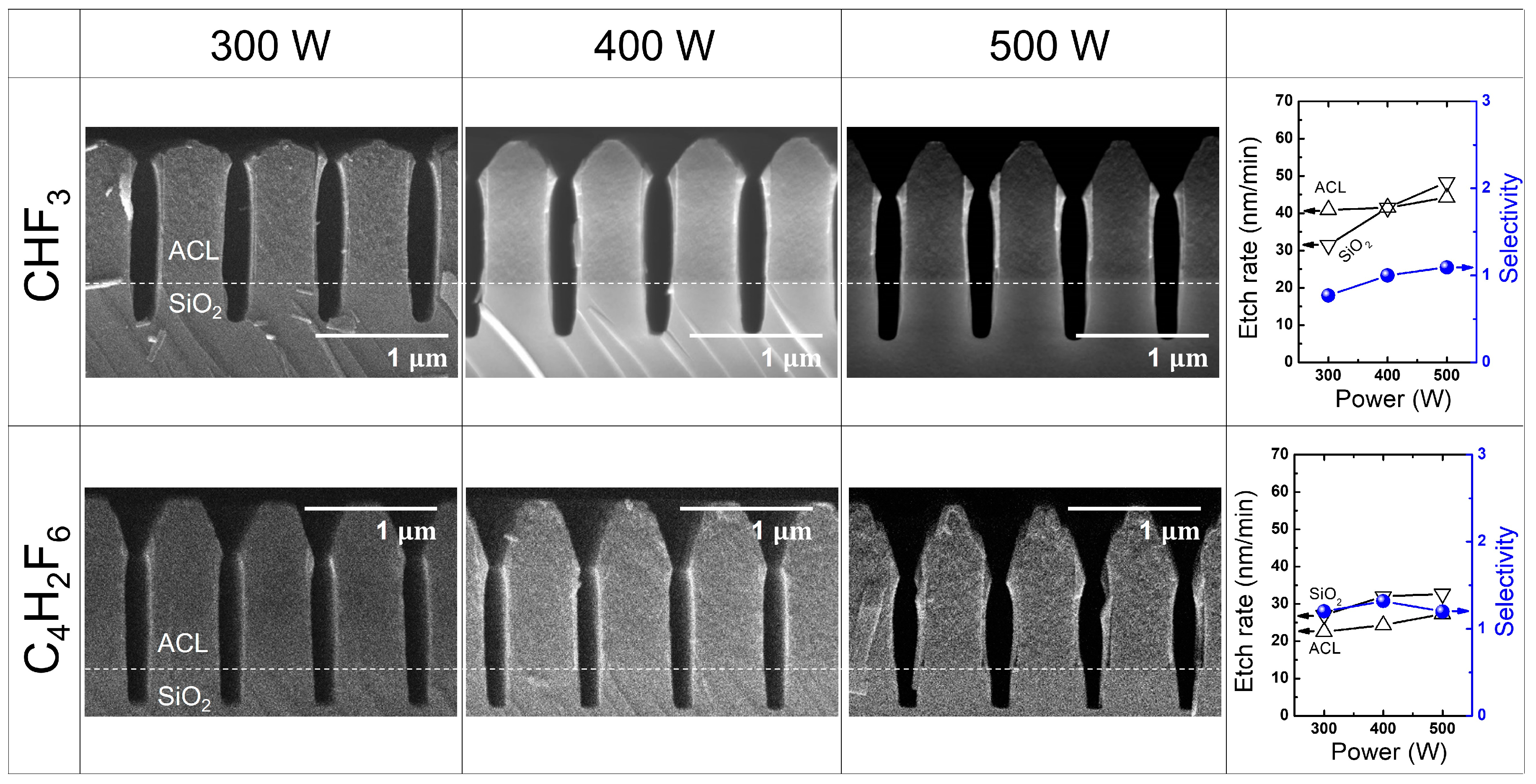
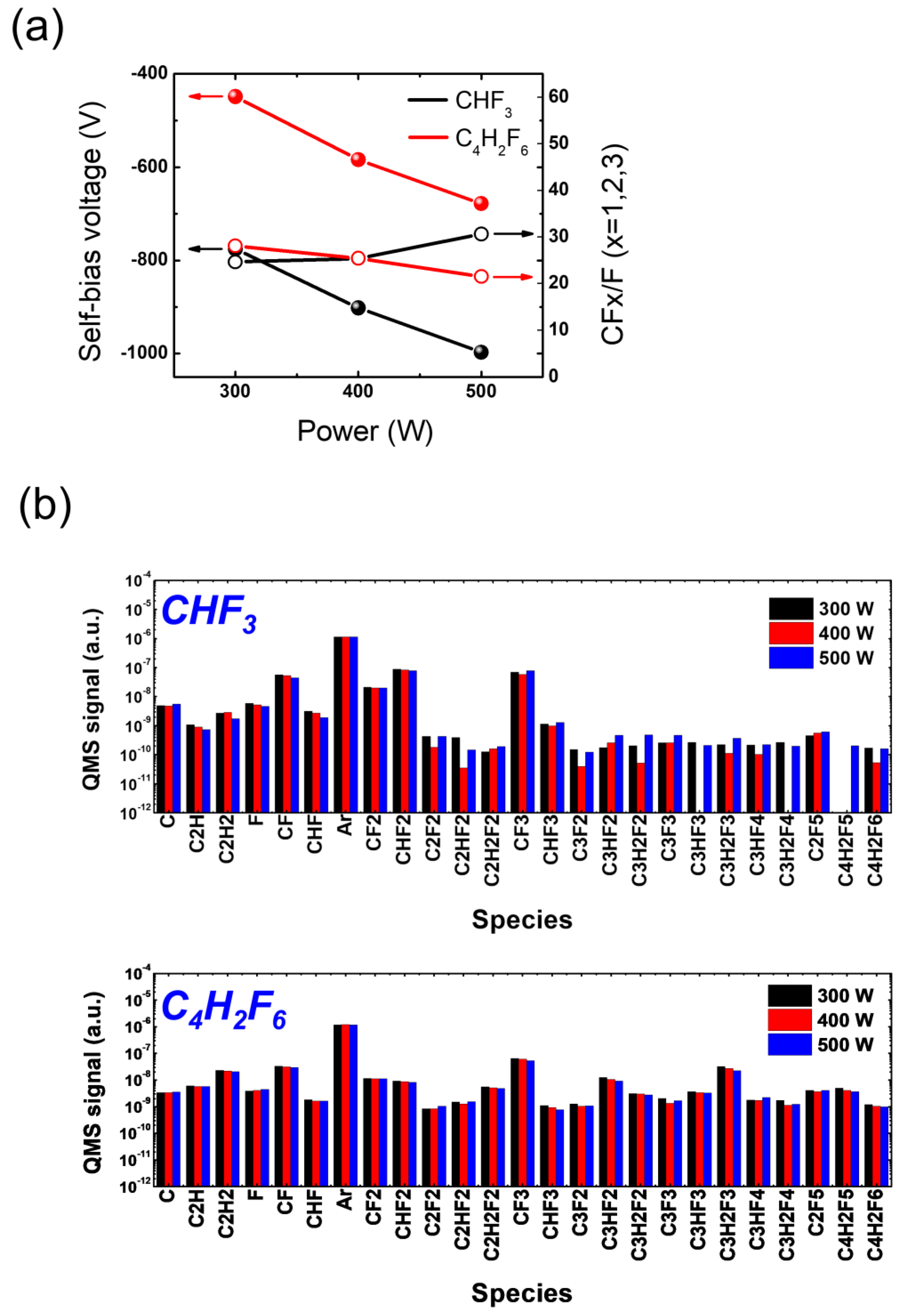
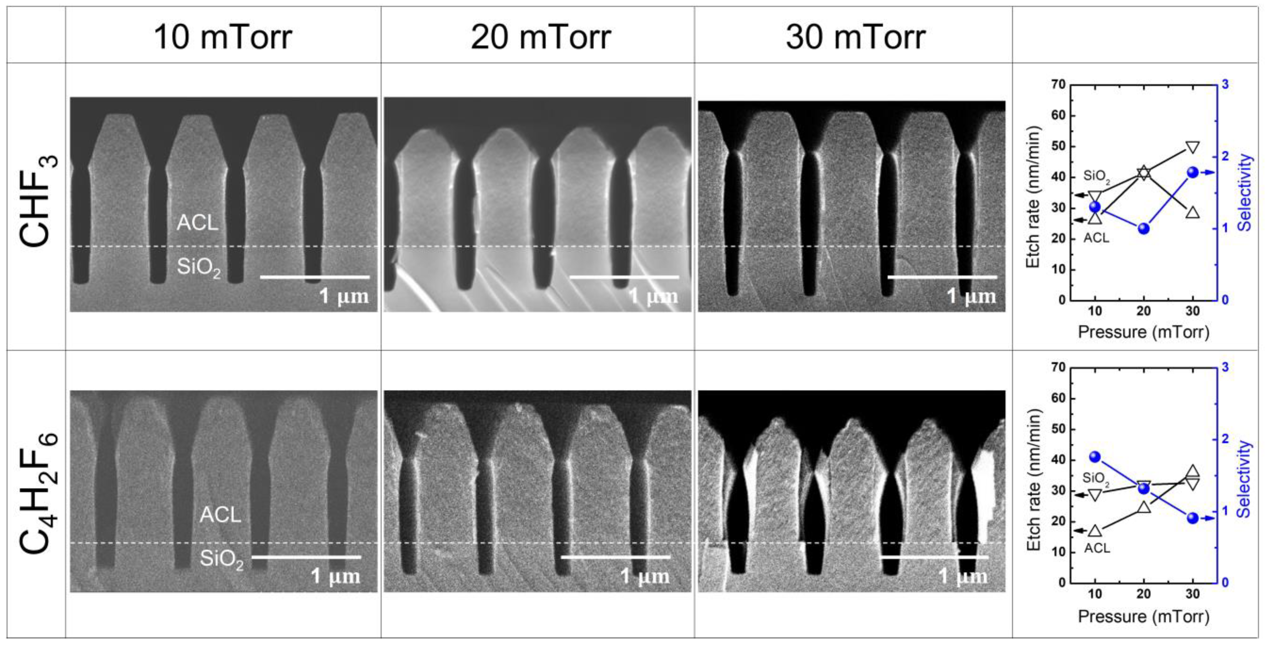
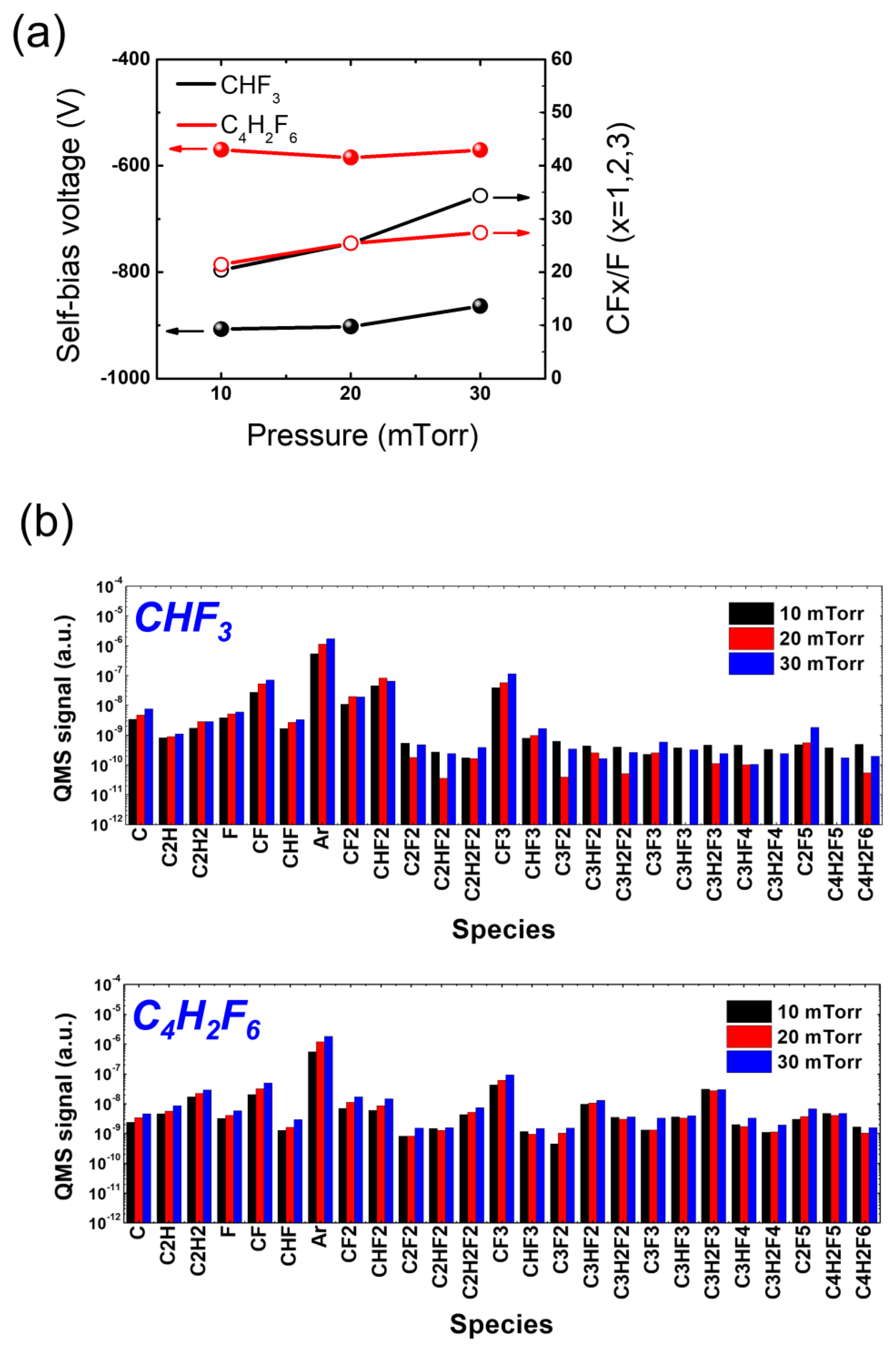
3.2. SiO2 Etching with HFC Precursors (CHF3 and C4H2F6)

Figure 7 presents the etch results obtained with different HFC precursors (CHF3 and C4H2F6) at varying RF power levels from 300 W to 500 W, while maintaining a fixed pressure of 20 mTorr. The resulting etch rates and selectivity values for C4F8 and C6F6 are summarized in the right-most column of Figure 7. It is commonly observed that as RF power increases, mask faceting tends to deteriorate, as evidenced in the etch results with C4F8 and C6F6. While the use of CHF3 produces nearly vertical ACL etch profiles, the utilization of C4H2F6 at an RF power of 500 W results in a distorted ACL etch profile. This distortion appears to be induced by the rough mask surface, which causes random ion scattering. However, when the RF power is set below 500 W, sharp and vertical trench etching can be achieved without any defects, such as bowing.
Regarding the etch rate and selectivity, CHF3 exhibits a SiO2 etch rate lower than that of ACL. As RF power increases, this trend is reversed, leading to a selectivity slightly above unity. On the other hand, with C4H2F6, both the SiO2 and ACL etch rates gradually increase as RF power increases. The etch rate of SiO2 remains slightly higher than that of ACL, while the selectivity remains above unity, even at an RF power of 500 W when the mask sidewall is distorted, possibly due to random ion scattering. Although the SiO2 etch rate with C4H2F6 is slightly lower than that with CHF3, the use of C4H2F6 yields a comparable etch selectivity with that of CHF3. Additionally, with minor optimization of the processing pressure, such as decreasing the pressure as demonstrated in Figure 7b, a fine etch profile could be achieved.
Figure 8a depicts the measured self-bias voltage (left y-axis) and the CFx/F (x = 1, 2, 3) ratio (right y-axis) as a function of applied RF power using CHF3 and C4H2F6. As the RF power increases, both CHF3 and C4H2F6 show an increase in the absolute value of the self-bias voltages, indicating an increase in the ion bombardment energy. Notably, the absolute value of the self-bias voltages with CHF3 at different RF powers is approximately twice that with C4H2F6, indicating more intense ion bombardment during etching with CHF3 compared with C4H2F6. This higher ion energy can be advantageous for HARC etching, where sufficient ion energy is required to reach the trench bottom. Etching with C4H2F6 would therefore require additional biasing to enhance the ion bombardment in order to match that achieved with CHF3.
Figure 8b presents the signal of various radical species resulting from the dissociation of CHF3 and C4H2F6, which varies with increasing RF power. As the RF power increases, CHF3 and C4H2F6 show different trends of radical signal variation species by species. Specifically, F from CHF3 decreases with increasing RF power, while that from C4H2F6 increases slightly. Those trends, however, do not follow the etch rate trend that changes with an increase in RF power, which might be attributed to a complex contribution of other FC radicals to the etch rate. When comparing CHF3 and C4H2F6, it is noteworthy that C4H2F6 yields carbon-rich radical species that contain multiple carbon atoms in their chemical structure, while CHF3 generates them to a lesser extent. This difference is expected since the generation of such carbon-rich radicals from CHF3 dissociation requires additional recombination processes between carbon-containing species such as CF2 and CHF2, which have relatively low reaction rates. However, this particular behavior does not appear to have a significant impact on ACL-masked SiO2 etching. Despite the prevalence of carbon-rich radicals in the process, the use of C4H2F6, as shown in Figure 7, does not demonstrate substantial advantages in terms of ACL mask protection or SiO2 trench profiles.
Nevertheless, it may be meaningful to focus on the difference in radical compositions between CHF3 and C4H2F6, particularly in relation to the major dissociation fractions of CHF3, rather than solely considering the evident difference in plasma chemistry between the two gases. This is because the major species resulting from CHF3 dissociation could play a critical role in determining the etch results. In Figure 8b, it can be observed that C4H2F6 dissociation yields comparable densities for most major species compared with CHF3 fractions. However, the densities of C2H2 and CHF2 are significantly lower with C4H2F6 than with CHF3. Furthermore, it is found that the densities of major species are barely affected by RF power variation, suggesting the need for another control parameter to manipulate plasma conditions.
Figure 9 illustrates the etch results obtained with different HFC precursors (CHF3 and C4H2F6) at varying pressures from 10 mTorr to 30 mTorr, with a fixed RF power of 400 W. The resulting etch rate and selectivity for the CHF3 and C4H2F6 cases are summarized in the right-most column of Figure 9.
When etching with CHF3, an interesting trend is observed. The ACL etch rate initially decreases and then rebounds as the mask faceting reduces, while the SiO2 etch rate monotonically increases. This behavior leads to a minimum selectivity at the intermediate pressure of 20 mTorr. In contrast, when using C4H2F6, ACL etching continuously increases with enhanced mask faceting as the pressure rises, resulting in significant bowing at the mask sidewall. At the same time, SiO2 etch rate shows minimal change with increasing pressure, leading to a substantial decrease in etch selectivity.
These findings highlight the importance of pressure control in achieving desirable etch results. With CHF3, an optimal pressure range can be identified to balance ACL etch rate and SiO2 etch rate, thereby maximizing selectivity. On the other hand, C4H2F6 exhibits challenges in maintaining selectivity as pressure increases, leading to distorted mask sidewalls and reduced etch performance.
Overall, understanding the pressure-dependent behavior of different HFC precursors is crucial for optimizing the etching process and achieving the desired etch profiles and selectivity.
Figure 10a illustrates the measured self-bias voltage (left y-axis) and the CFx/F (x = 1, 2, 3) ratio (right y-axis) as a function of pressure for CHF3 and C4H2F6. It is observed that with increasing pressure, both CHF3 and C4H2F6 show no significant change in the self-bias voltages. However, it is important to note that CHF3 consistently provides higher absolute self-bias voltages compared with C4H2F6 across a wide range of pressures. This indicates the ion bombardment during etching is stronger with CHF3 than with C4H2F6 owing to higher ion density and energy. This difference in ion bombardment strength may be linked to the higher SiO2 etch rate observed with CHF3 compared with C4H2F6.
In Figure 10b, the signal of various radical species resulting from the dissociation of CHF3 and C4H2F6 is presented as a function of increasing pressure. As previously observed in Figure 8b, carbon-rich radical species containing multiple carbon atoms in their chemical structure are significantly observed with C4H2F6, while they are barely present with CHF3. Such carbon-rich species are believed to react with ACL, enhancing its etching rather than passivating the ACL surface. Additionally, the key etchants of FC plasmas, CF2 and CHF2, are observed to exhibit reversed relative densities depending on the precursor used. In the case of CHF3, the CF2 signal is lower than that of CHF2, whereas CF2 exceeds CHF2 with C4H2F6. This reversal in CF2 and CHF2 densities between the two precursors would be useful in selective etching of SiO2 over Si3N4 [47].

3.3. Evaluation of the Greenhouse Effect

Overall, our results demonstrate that the conventional FC gases of C4F8 and CHF3 exhibit a more vertical etch profile and a higher SiO2 etch rate across different power and pressure conditions. On the other hand, the alternative gases of C6F6 and C4H2F6 exhibit improved etch selectivity. However, when evaluating the etch performance of low GWP gases, it is crucial to assess the reduction in GHG emissions achieved by their implementation.
To quantify the environmental impact, we employ the million metric tons of carbon dioxide equivalents (MMTCDE) metric, which allows for a comparison of GHG emissions based on their GWP. This metric is particularly useful when a GHG is emitted in significantly smaller quantities compared with the reference amount of 1 ton. The carbon dioxide equivalent for a gas is derived as below.
M M T C D E = Q × G W P 100 10 9
In Equation (1), Q refers to the mass of a GHG emitted, measured in kg. To calculate Q for each PFC or HFC gas, we multiply the flow rate of the FC gases used for etching (10 sccm) by the processing time (10 min) to obtain the volumetric amount of the gas used. This value is then converted to mass in kg, taking into account the atomic mass unit of the gas. It should be noted that, in calculating the MMTCDE, we employ the mass of mother gas species, such as C4F8 and CHF3, rather than their fractions, including CF and CF2, that are observed by the RGA. This is based on a presumption that such reactive species would have relatively short lifetimes and thus have less affect global warming at the atmosphere compared with the chemically stable non-reactive molecules.
Figure 11 illustrates a comparison of the estimated MMTCDEs for the conventional gases (C4F8 and CHF3) and the alternative gases (C6F6 and C4H2F6). The MMTCDE comparisons under the other experimental conditions show a nearly identical result so that we introduce only the result under etching conditions of 20 mTorr pressure and 400 W RF power for succinctness. Notably, the MMTCDEs associated with the alternative gases are approximately three orders of magnitude lower than those with the conventional gases, despite the etch results showing little difference. This observation suggests that the investigated alternative gases, C6F6 and C4H2F6, hold significant promise as candidates for reducing GHG emissions in the semiconductor industry.
It should be noted, however, that the above MMTCDE evaluation may not be sufficient since it is conducted only in the processing chamber, not at the exhaust line of the chamber. Even though low-GWP precursors such as C6F6 and C4H2F6, which are investigated in this work, are utilized in plasma processes, undesired high-GWP molecules such as C2F6 with 11,000 GWP can be created and exhausted into the atmosphere, which may reduce the benefits from the low-GWP precursors employment. Additionally, the MMTCDE evaluation with QMS could also include a certain level of inaccuracy due to the dissociative ionization by high-energy electron impacts. Thus, evaluating MMTCDE at the exhaust line of the vacuum chamber with non-invasive diagnostic tools would lead to more rigorous analysis on the global warming effects.

4. Concluding Remarks

In this study, we have explored the etch performance of C6F6 and C4H2F6 as alternatives to the conventional etch gases, C4F8 and CHF3, respectively, with the goal of reducing GHG emissions during plasma etching. Given the significantly lower GWP of the alternative gases, it is encouraging to investigate whether they can deliver comparable etch performance to the conventional gases.
To evaluate their performance, we conducted etching experiments using gas mixtures of different FC gases under various conditions of RF power and pressure. The obtained results were carefully analyzed using SEM images. Specifically, we compared the etch results of C4F8 with those of C6F6, and the etch results of CHF3 with those of C4H2F6.
Our findings indicate that the alternative gases demonstrated comparable etch performance to the conventional gases across various conditions. This suggests that the alternative gases hold promise for utilization in the next-generation etch processes with reduced GHG emissions. Importantly, our MMTCDE estimation revealed that replacing the conventional gases with the alternative gases could result in GHG emissions reduction by several orders of magnitude.
The outcomes of this study are expected to contribute to the wider adoption of low-GWP gases in semiconductor manufacturing. By incorporating these alternative gases into the etch processes, the industry can effectively reduce its environmental impact while maintaining the desired etch performance. Further research and development efforts should be directed towards optimizing the use of low-GWP gases and promoting their integration into commercial semiconductor fabrication processes.

Author Contributions

Conceptualization, M.C. and Y.L.; validation, M.C., Y.L., Y.Y., C.C., W.J., I.S., B.C., S.K. and Y.S.; formal analysis, M.C. and Y.L., investigation, M.C.; resources, G.Y.Y.; writing—original draft preparation, Y.L.; writing—review and editing, C.C., I.S. and S.K.; supervision, S.Y.; funding acquisition, M.C. and S.Y. All authors have read and agreed to the published version of the manuscript.

Funding

This research was supported by a National Research Council of Science & Technology (NST) grant funded by the Korean government (MSIP) (CRF-20-01-NFRI), by the Technology Innovation Program (or Industrial Strategic Technology Development Program) (RS-2023-00236642, RS-2023-00236177) funded By the Ministry of Trade, Industry & Energy (MOTIE, Korea) (1415187459), by the MOTIE (1415181071, 1415180221) and KSRC (Korea Semiconductor Research Consortium) (20019500, 20019473) support program for the development of future semiconductor devices, by a Korea Institute for Advancement of Technology (KIAT) grant funded by the Korean Government (MOTIE) (P0008458, HRD Program for Industrial Innovation), by the Basic Science Research Program through the National Research Foundation of Korea (NRF) funded by the Ministry of Education (NRF-2020R1A6A1A03047771), by the KIMM Institutional Program (NK236F) and NST/KIMM, by “Regional Innovation Strategy (RIS)” through the National Research Foundation of Korea (NRF) funded by the Ministry of Education (MOE) (2021RIS-004), and by R&D Program of “Plasma Convergence & Fundamental Research Project (EN2321-11)” through the Korea Institute of Fusion Energy (KFE) funded by the Government funds, Republic of Korea.

Institutional Review Board Statement

Not applicable.

Informed Consent Statement

Not applicable.

Data Availability Statement

The data presented in this study are available on request from the corresponding author.

Conflicts of Interest

The authors declare no conflict of interest.

References

  1. Samukawa, S.; Hori, M.; Rauf, S.; Tachibana, K.; Bruggeman, P.; Kroesen, G.; Whitehead, J.C.; Murphy, A.B.; Gutsol, A.F.; Starikovskaia, S.; et al. The 2012 Plasma Roadmap. J. Phys. D Appl. Phys. 2012, 45, 253001. [Google Scholar] [CrossRef]
  2. Adamovich, I.; Baalrud, S.D.; Bogaerts, A.; Bruggeman, P.J.; Cappelli, M.; Colombo, V.; Czarnetzki, U.; Ebert, U.; Eden, J.G.; Favia, P.; et al. The 2017 Plasma Roadmap: Low temperature plasma science and technology. J. Phys. D Appl. Phys. 2017, 50, 323001. [Google Scholar] [CrossRef]
  3. Donnelly, V.M.; Kornblit, A. Plasma etching: Yesterday, today, and tomorrow. J. Vac. Sci. Technol. A Vac. Surf. Film. 2013, 31, 050825. [Google Scholar] [CrossRef] [Green Version]
  4. Constantine, C. Plasma etching of III–V semiconductors in CH4/H2/Ar electron cyclotron resonance discharges. J. Vac. Sci. Technol. B Microelectron. Nanometer Struct. 1990, 8, 596–606. [Google Scholar] [CrossRef]
  5. Vartuli, C.B.; Pearton, S.J.; Lee, J.W.; Hong, J.; MacKenzie, J.D.; Abernathy, C.R.; Shul, R.J. ICl/Ar electron cyclotron resonance plasma etching of III–V nitrides. Appl. Phys. Lett. 1996, 69, 1426–1428. [Google Scholar] [CrossRef]
  6. Tang, C.C.; Hess, D.W. Tungsten Etching in CF4 and SF6 Discharges. J. Electrochem. Soc. 1984, 131, 115–120. [Google Scholar] [CrossRef]
  7. Turban, A.P.a.G. Plasma Etching of Refractory Metals (W, Mo, Ta) and Silicon in SF6 and SF6-O2. An Analysis of the Reaction Products. Plasma Chem. Plasma Process. 1985, 5, 333–351. [Google Scholar]
  8. Osipov, A.A.; Andrianov, N.A.; Speshilova, A.B.; Gagaeva, A.E.; Risquez, S.; Vorobyev, A.; Alexandrov, S.E. Highly Selective Plasma Etching Technique for Molybdenum. Plasma Chem. Plasma Process. 2023, 43, 697–707. [Google Scholar] [CrossRef]
  9. Gasvoda, R.J.; Zhang, Z.; Wang, S.; Hudson, E.A.; Agarwal, S. Etch selectivity during plasma-assisted etching of SiO2 and SiNx: Transitioning from reactive ion etching to atomic layer etching. J. Vac. Sci. Technol. A 2020, 38, 050803. [Google Scholar] [CrossRef]
  10. Volynets, V.; Barsukov, Y.; Kim, G.; Jung, J.-E.; Nam, S.K.; Han, K.; Huang, S.; Kushner, M.J. Highly selective Si3N4/SiO2 etching using an NF3/N2/O2/H2 remote plasma. I. Plasma source and critical fluxes. J. Vac. Sci. Technol. A 2020, 38, 023007. [Google Scholar] [CrossRef]
  11. Oehrlein, M.S.a.G.S. A Review of SiO2 Etching Studies in Inductively Coupled Fluorocarbon Plasmas. J. Electrochem. Soc. 2001, 148, 11. [Google Scholar] [CrossRef]
  12. Standaert, T.E.F.M.; Hedlund, C.; Joseph, E.A.; Oehrlein, G.S.; Dalton, T.J. Role of fluorocarbon film formation in the etching of silicon, silicon dioxide, silicon nitride, and amorphous hydrogenated silicon carbide. J. Vac. Sci. Technol. A Vac. Surf. Film. 2004, 22, 53–60. [Google Scholar] [CrossRef] [Green Version]
  13. Rueger, N.R.; Beulens, J.J.; Schaepkens, M.; Doemling, M.F.; Mirza, J.M.; Standaert, T.E.F.M.; Oehrlein, G.S. Role of steady state fluorocarbon films in the etching of silicon dioxide using CHF3 in an inductively coupled plasma reactor. J. Vac. Sci. Technol. A Vac. Surf. Film. 1997, 15, 1881–1889. [Google Scholar] [CrossRef] [Green Version]
  14. Schaepkens, M.; Standaert, T.E.F.M.; Rueger, N.R.; Sebel, P.G.M.; Oehrlein, G.S.; Cook, J.M. Study of the SiO2-to-Si3N4 etch selectivity mechanism in inductively coupled fluorocarbon plasmas and a comparison with the SiO2-to-Si mechanism. J. Vac. Sci. Technol. A Vac. Surf. Film. 1999, 17, 26–37. [Google Scholar] [CrossRef] [Green Version]
  15. Schaepkens, M.; Oehrlein, G.S.; Hedlund, C.; Jonsson, L.B.; Blom, H.-O. Selective SiO2-to-Si3N4 etching in inductively coupled fluorocarbon plasmas: Angular dependence of SiO2 and Si3N4 etching rates. J. Vac. Sci. Technol. A Vac. Surf. Film. 1998, 16, 3281–3286. [Google Scholar] [CrossRef]
  16. Rošková, Z.; Schneider, J.; Štengel, M. Predicted Hydrofluorocarbon (HFC) and Perfluorocarbon (PFC) Emissions for the Years 2010–2050 in the Czech Republic. Atmosphere 2023, 14, 111. [Google Scholar] [CrossRef]
  17. Mikhaylov, A.; Moiseev, N.; Aleshin, K.; Burkhardt, T. Global climate change and greenhouse effect. Entrep. Sustain. Issues 2020, 7, 2897–2913. [Google Scholar] [CrossRef]
  18. Available online: https://www.epa.gov/ghgemissions/understanding-global-warming-potentials (accessed on 7 August 2023).
  19. Myhre, G.; Shindell, D.; Bréon, F.-M.; Collins, W.; Fuglestvedt, J.; Huang, J.; Koch, D.; Lamarque, J.-F.; Lee, D.; Mendoza, B.; et al. Anthropogenic and Natural Radiative Forcing. In Climate Change 2013: The Physical Science Basis. Contribution of Working Group I to the Fifth Assessment Report of the Intergovernmental Panel on Climate Change; Stocker, T.F., Qin, D., Plattner, G.-K., Tignor, M., Allen, S.K., Boschung, J., Nauels, A., Xia, Y., Bex, V., Midgley, P.M., Eds.; Cambridge University Press: Cambridge, UK; New York, NY, USA, 2013. [Google Scholar]
  20. Yoro, K.O.; Daramola, M.O. CO2 emission sources, greenhouse gases, and the global warming effect. In Advances in Carbon Capture; Woodhead Publishing: Sawston, UK, 2020; pp. 3–28. [Google Scholar] [CrossRef]
  21. Kweku, D.; Bismark, O.; Maxwell, A.; Desmond, K.; Danso, K.; Oti-Mensah, E.; Quachie, A.; Adormaa, B. Greenhouse Effect: Greenhouse Gases and Their Impact on Global Warming. J. Sci. Res. Rep. 2018, 17, 1–9. [Google Scholar] [CrossRef]
  22. Kweku, D.W.; Bismark, O.; Maxwell, A.; Desmond, K.A.; Danso, K.B.; Oti-Mensah, E.A.; Quachie, A.T.; Adormaa, B.B. Benefits, Costs, and Cooperation in Greenhouse Gas Abatement. Clim. Chang. 2000, 47, 239–258. [Google Scholar]
  23. Sung, D.; Wen, L.; Tak, H.; Lee, H.; Kim, D.; Yeom, G. Investigation of SiO2 Etch Characteristics by C6F6/Ar/O2 Plasmas Generated Using Inductively Coupled Plasma and Capacitively Coupled Plasma. Materials 2022, 15, 1300. [Google Scholar] [CrossRef]
  24. Kim, Y.; Kim, S.; Kang, H.; You, S.; Kim, C.; Chae, H. Low Global Warming C4H3F7O Isomers for Plasma Etching of SiO2 and Si3N4 Films. ACS Sustain. Chem. Eng. 2022, 10, 10537–10546. [Google Scholar] [CrossRef]
  25. Lim, N.; Choi, Y.S.; Efremov, A.; Kwon, K.H. Dry Etching Performance and Gas-Phase Parameters of C6F12O + Ar Plasma in Comparison with CF4 + Ar. Materials 2021, 14, 1595. [Google Scholar] [CrossRef] [PubMed]
  26. Nakamura, M.; Hori, M.; Goto, T.; Ito, M.; Ishii, N. Spatial distributions of the absolute CF and CF2 radical densities in high-density plasma employing low global warming potential fluorocarbon gases and precursors for film formation. J. Vac. Sci. Technol. A Vac. Surf. Film. 2001, 19, 2134–2141. [Google Scholar] [CrossRef]
  27. Lee, H.S.; Yang, K.C.; Kim, S.G.; Shin, Y.J.; Suh, D.W.; Song, H.D.; Lee, N.E.; Yeom, G.Y. SiO2 etch characteristics and environmental impact of Ar/C3F6O chemistry. J. Vac. Sci. Technol. A 2018, 36, 061306. [Google Scholar] [CrossRef]
  28. A N Goyette, Y.W.a.J.K.O. Inductively coupled plasmas in low global-warming-potential gases. J. Phys. D Appl. Phys. 2000, 33, 2004–2009. [Google Scholar] [CrossRef] [Green Version]
  29. Park, J.W.; Chae, M.G.; Kim, D.S.; Lee, W.O.; Song, H.D.; Choi, C.; Yeom, G.Y. In situ dry cleaning of Si wafer using OF2/NH3 remote plasma with low global warming potential. J. Phys. D Appl. Phys. 2018, 51, 445201. [Google Scholar] [CrossRef] [Green Version]
  30. You, S.; Lee, Y.J.; Chae, H.; Kim, C.-K. Plasma Etching of SiO2 Contact Holes Using Hexafluoroisopropanol and C4F8. Coatings 2022, 12, 679. [Google Scholar] [CrossRef]
  31. Papadimitriou, V.C.; Spitieri, C.S.; Papagiannakopoulos, P.; Cazaunau, M.; Lendar, M.; Daele, V.; Mellouki, A. Atmospheric chemistry of (CF3)2C=CH2: OH radicals, Cl atoms and O3 rate coefficients, oxidation end-products and IR spectra. Phys. Chem. Chem. Phys. 2015, 17, 25607–25620. [Google Scholar] [CrossRef]
  32. Jeong, W.N.; Lee, Y.S.; Cho, C.H.; Seong, I.H.; You, S.J. Investigation into SiO2 Etching Characteristics Using Fluorocarbon Capacitively Coupled Plasmas: Etching with Radical/Ion Flux-Controlled. Nanomaterials 2022, 12, 4457. [Google Scholar] [CrossRef]
  33. Seong, I.H.; Lee, J.J.; Cho, C.H.; Lee, Y.S.; Kim, S.J.; You, S.J. Characterization of SiO2 over Poly-Si Mask Etching in Ar/C4F8 Capacitively Coupled Plasma. Appl. Sci. Converg. Technol. 2021, 30, 176–182. [Google Scholar] [CrossRef]
  34. Cho, C.; You, K.; Kim, S.; Lee, Y.; Lee, J.; You, S. Characterization of SiO2 Etching Profiles in Pulse-Modulated Capacitively Coupled Plasmas. Materials 2021, 14, 5036. [Google Scholar] [CrossRef] [PubMed]
  35. Lee, Y.; Oh, S.; Lee, J.; Cho, C.; Kim, S.; You, S. A Quantification Method in Quadrupole Mass Spectrometer Measurement. Appl. Sci. Converg. Technol. 2021, 30, 50–53. [Google Scholar] [CrossRef]
  36. Yoo, S.-W.; Cho, C.; Kim, K.; Lee, H.; You, S. Characteristics of SiO2 Etching by Capacitively Coupled Plasma with Different Fluorocarbon Liquids (C7F14, C7F8) and Fluorocarbon Gas (C4F8). Appl. Sci. Converg. Technol. 2021, 30, 102–106. [Google Scholar] [CrossRef]
  37. Yeom, H.J.; Lee, J.J.; Kim, S.J.; Lee, Y.S.; Cho, C.h.; Kim, J.H.; Lee, H.-C.; You, S. Mass Filter Characteristic and Design Role of Quadrupole Mass Spectrometer for Radical Measurement in Low-pressure Plasmas. Appl. Sci. Converg. Technol. 2020, 29, 77–81. [Google Scholar] [CrossRef]
  38. Singh, H.; Coburn, J.W.; Graves, D.B. Mass spectrometric detection of reactive neutral species: Beam-to-background ratio. J. Vac. Sci. Technol. A Vac. Surf. Film. 1999, 17, 2447–2455. [Google Scholar] [CrossRef]
  39. Lee, Y.; Yeom, H.; Choi, D.; Kim, S.; Lee, J.; Kim, J.; Lee, H.; You, S. Database Development of SiO2 Etching with Fluorocarbon Plasmas Diluted with Various Noble Gases of Ar, Kr, and Xe. Nanomaterials 2022, 12, 3828. [Google Scholar] [CrossRef]
  40. Singh, H.; Coburn, J.W.; Graves, D.B. Appearance potential mass spectrometry: Discrimination of dissociative ionization products. J. Vac. Sci. Technol. A Vac. Surf. Film. 2000, 18, 299–305. [Google Scholar] [CrossRef]
  41. Lichtenberg, A.J. Principles of Plasma Discharges and Materials Processing, 2nd ed.; John Wiley & Sons, Inc.: Hoboken, NJ, USA, 2005; p. 800. [Google Scholar] [CrossRef] [Green Version]
  42. Lee, Y.; Seong, I.; Lee, J.; Lee, S.; Cho, C.; Kim, S.; You, S. Various evolution trends of sample thickness in fluorocarbon film deposition on SiO2. J. Vac. Sci. Technol. A 2021, 40, 013001. [Google Scholar] [CrossRef]
  43. Coburn, J.W.; Winters, H.F. Ion- and electron-assisted gas-surface chemistry—An important effect in plasma etching. J. Appl. Phys. 1979, 50, 3189–3196. [Google Scholar] [CrossRef]
  44. Vasenkov, A.V.; Li, X.; Oehrlein, G.S.; Kushner, M.J. Properties of c-C4F8 inductively coupled plasmas. II. Plasma chemistry and reaction mechanism for modeling for Ar/c-C4F8/O2 discharges. J. Vac. Sci. Technol. A 2004, 22, 20. [Google Scholar] [CrossRef] [Green Version]
  45. Matsui, M.; Tatsumi, T.; Sekine, M. Relationship of etch reaction and reactive species flux in C4F8/Ar/O2 plasma for SiO2 selective etching over Si and Si3N4. J. Vac. Sci. Technol. A Vac. Surf. Film. 2001, 19, 2089–2096. [Google Scholar] [CrossRef]
  46. Jeong, W.; Kim, S.; Lee, Y.; Cho, C.; Seong, I.; You, Y.; Choi, M.; Lee, J.; Seol, Y.; You, S. Contribution of Ion Energy and Flux on High-Aspect Ratio SiO2 Etching Characteristics in a Dual-Frequency Capacitively Coupled Ar/C4F8 Plasma: Individual Ion Energy and Flux Controlled. Materials 2023, 16, 3820. [Google Scholar] [CrossRef] [PubMed]
  47. Honda, M.; Katsunuma, T.; Tabata, M.; Tsuji, A.; Oishi, T.; Hisamatsu, T.; Ogawa, S.; Kihara, Y. Benefits of atomic-level processing by quasi-ALE and ALD technique. J. Phys. D Appl. Phys. 2017, 50, 234002. [Google Scholar] [CrossRef]
Figure 1. Schematic of the experimental setup.
Materials 16 05624 g001
Figure 2. Reference SEM image of an un-etched SiO2 coupon wafer.
Materials 16 05624 g002
Figure 3. SEM images of the etch profile evolution with C4F8 and C6F6 at varying RF power from 300 W to 500 W. The pressure is maintained at 20 mTorr by controlling the Ar flow rate. The etch rate and selectivity with each precursor are plotted in the right-most column.
Materials 16 05624 g003
Figure 4. (a) Self-bias voltage and (b) radical species signal at varying RF power with PFC gas mixtures of C4F8 and C6F6. The pressure is maintained at 20 mTorr.
Materials 16 05624 g004
Figure 5. SEM images of the etch profile evolution with C4F8 and C6F6 at varying pressure from 10 mTorr to 30 mTorr. The RF power is maintained at 400 W. The etch rate and selectivity with each precursor are plotted in the right-most column.
Materials 16 05624 g005
Figure 6. (a) Self-bias voltage and (b) radical species signal at varying pressure with PFC gas mixtures of C4F8 and C6F6. The RF power is maintained at 400 W.
Materials 16 05624 g006
Figure 7. SEM images of the etch profile evolution with CHF3 and C4H2F6 at varying RF power from 300 W to 500 W. The pressure is maintained at 20 mTorr by controlling the Ar flow rate. The etch rate and selectivity with each precursor are plotted in the right-most column.
Materials 16 05624 g007
Figure 8. (a) Self-bias voltage and (b) radical species signal at varying RF power with HFC gas mixtures of CHF3 and C4H2F6. The pressure is maintained at 20 mTorr.
Materials 16 05624 g008
Figure 9. SEM images of the etch profile evolution with CHF3 and C4H2F6 at varying pressure from 10 mTorr to 30 mTorr. The RF power is maintained at 400 W. The etch rate and selectivity with each precursor are plotted in the right-most column.
Materials 16 05624 g009
Figure 10. (a) Self-bias voltage and (b) radical species signal at varying pressure with HFC gas mixtures of CHF3 and C4H2F6. The RF power is maintained at 400 W.
Materials 16 05624 g010
Figure 11. MMTCDE of the investigated etching gases during the etch process under the condition of 400 W RF power, 20 mTorr pressure, and 10 min duration.
Materials 16 05624 g011
Table 1. The atmospheric lifetime and GWP100 of the investigated PFC and HFC precursors.
NameMolecular FormulaAtmospheric
Lifetime (Years)
GWP100Reference
OctafluorocyclobutaneC4F832009540[19]
HexafluorobenzeneC6F60.237[23]
TrifluoromethaneCHF322212,400[19]
Hexafluoro-isobutyleneC4H2F60.032.8[31]
Table 2. The experimental conditions for the examined etching processes.
Power
(W)
Pressure
(mTorr)
Duration
(min)
Gas Flow Rate
(sccm)
Electrode Temperature (°C)
300–50010–301020 for Ar
10 for FC
10
Disclaimer/Publisher’s Note: The statements, opinions and data contained in all publications are solely those of the individual author(s) and contributor(s) and not of MDPI and/or the editor(s). MDPI and/or the editor(s) disclaim responsibility for any injury to people or property resulting from any ideas, methods, instructions or products referred to in the content.

