

A Comparison of Conical and Cylindrical Implants Inserted in an In Vitro Post-Extraction Model Using Low-Density Polyurethane Foam Blocks


 ,
,  ,
,  ,
,  ,
, 
Abstract
1. Introduction
2. Materials and Methods
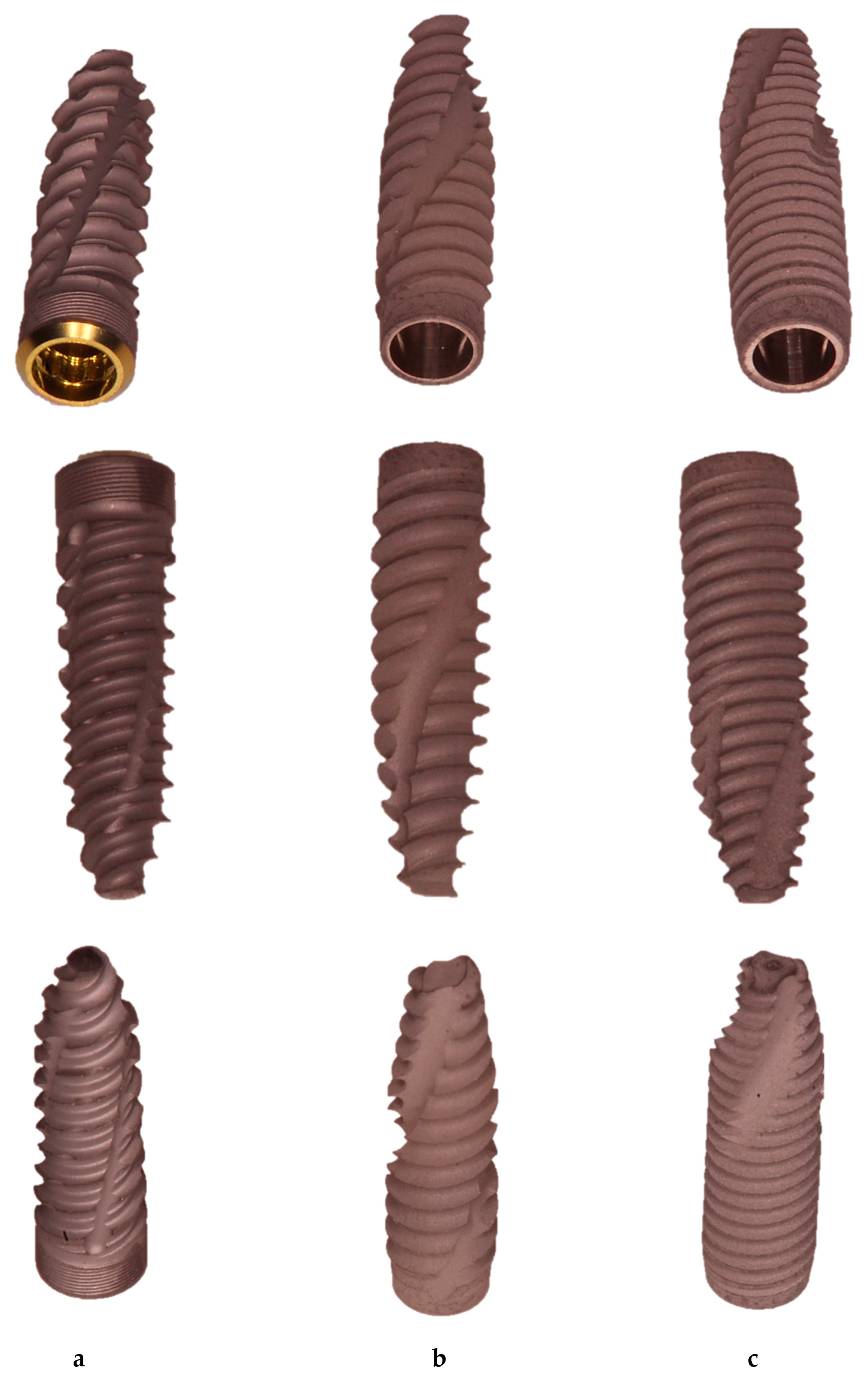
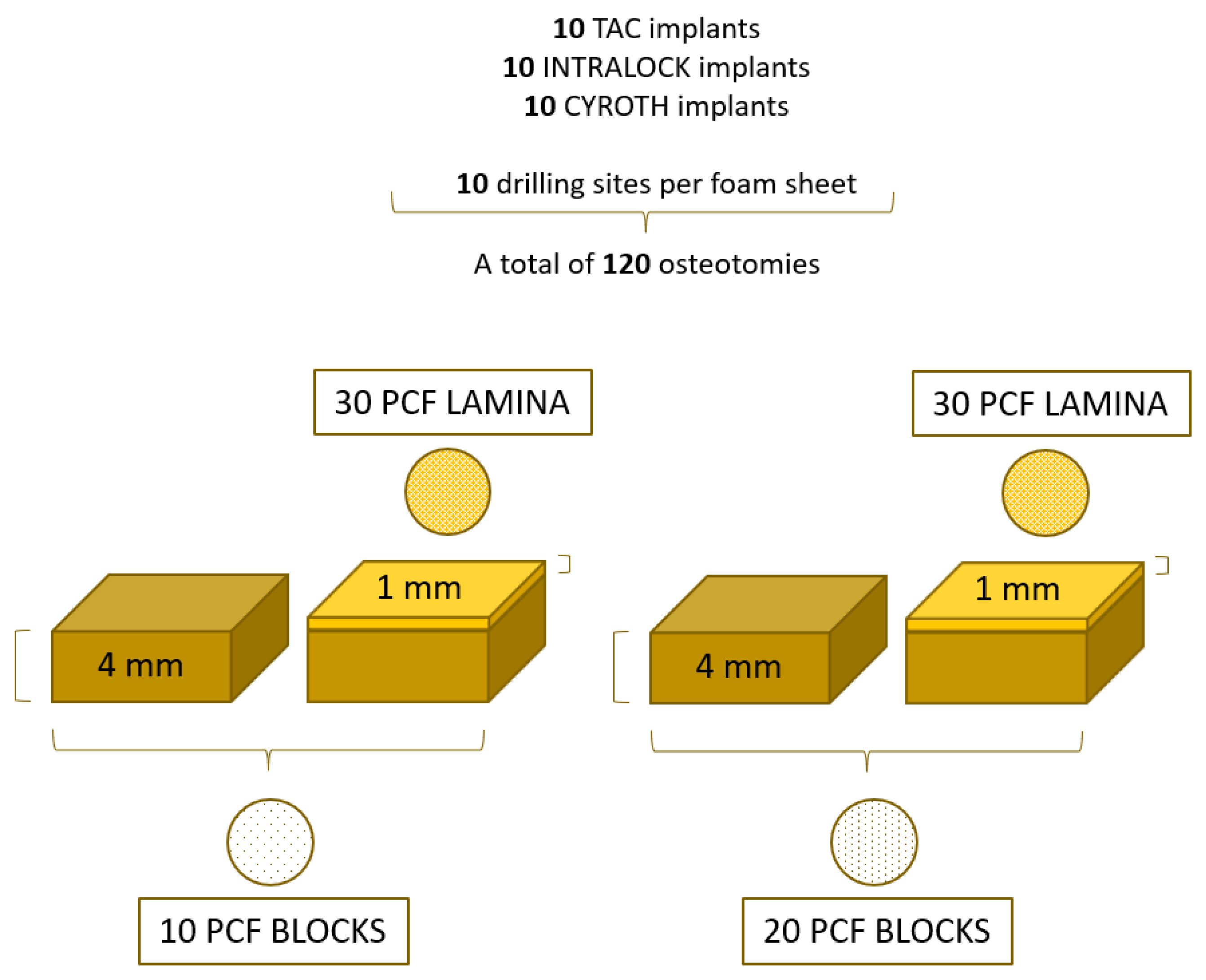
2.1. Implant Description
- TAC conical implants (Aon Implants, Grisignano di Zocco, Italy);
- INTRALOCK conical implants (Intra-Lock System Europa Spa, Salerno, Italy);
- CYROTH cylindrical implants (Aon Implants, Grisignano di Zocco, Italy).
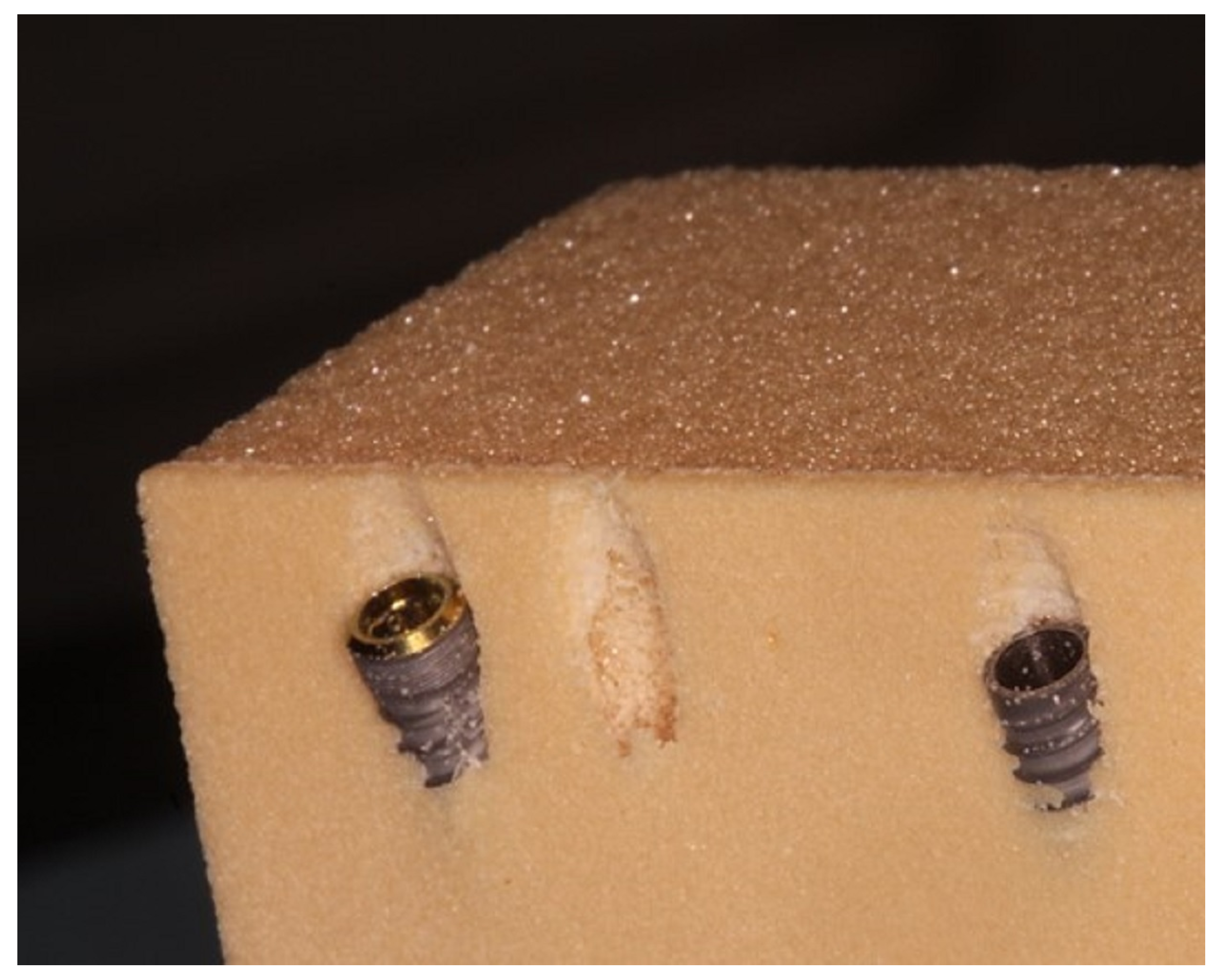
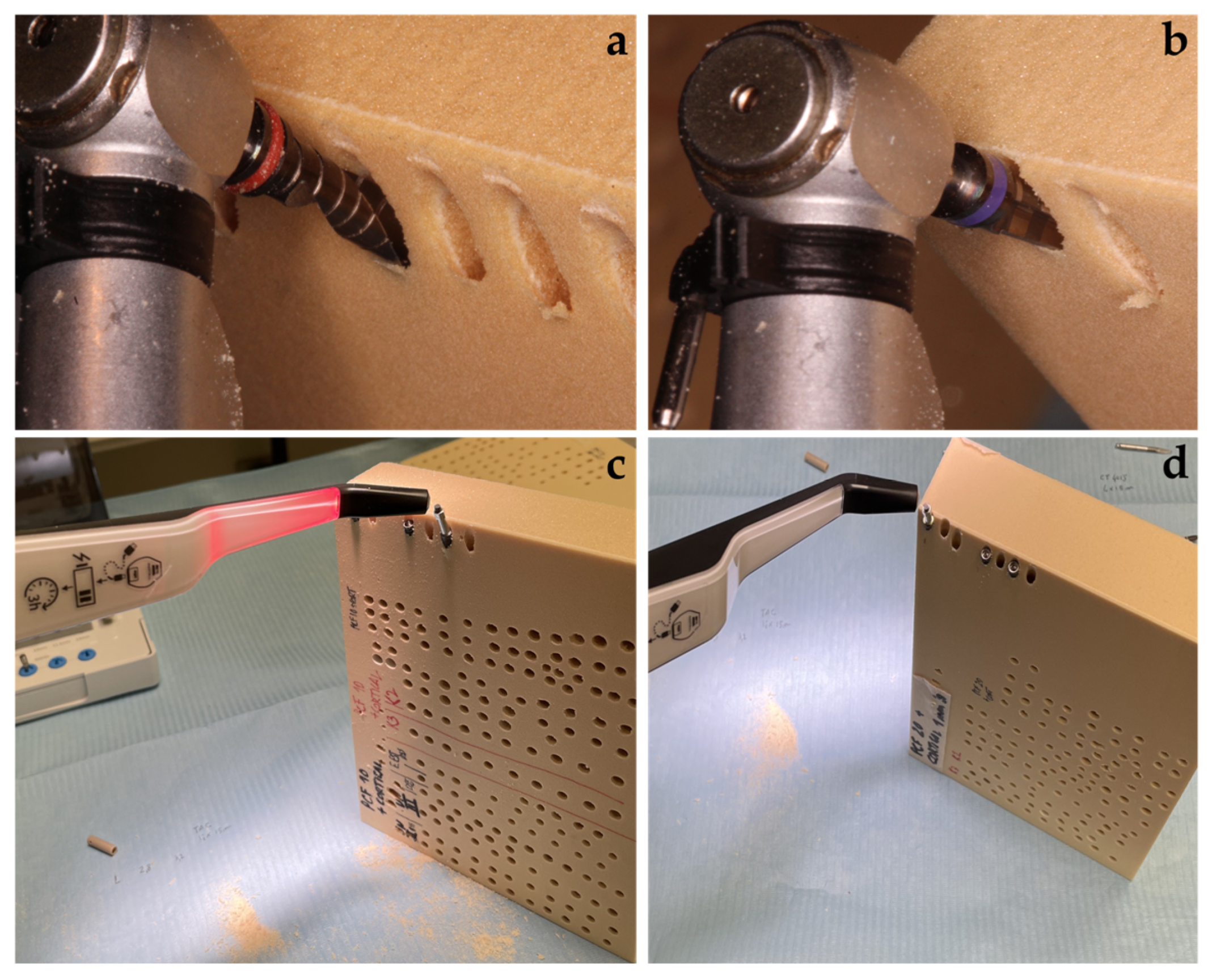
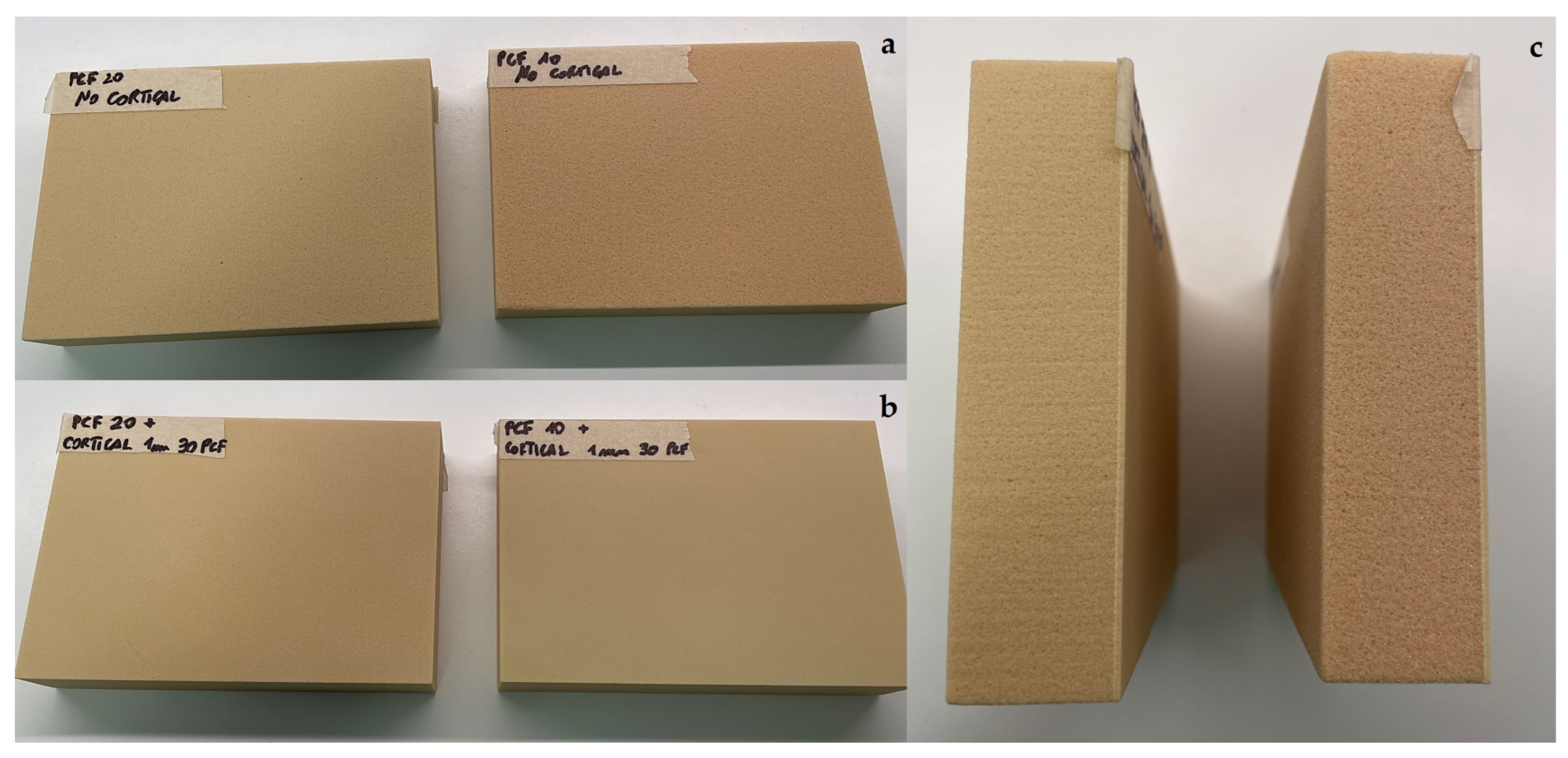
2.2. Drilling Protocol and Implant Insertion
2.3. Study Design
2.4. Statistical Analysis
3. Results
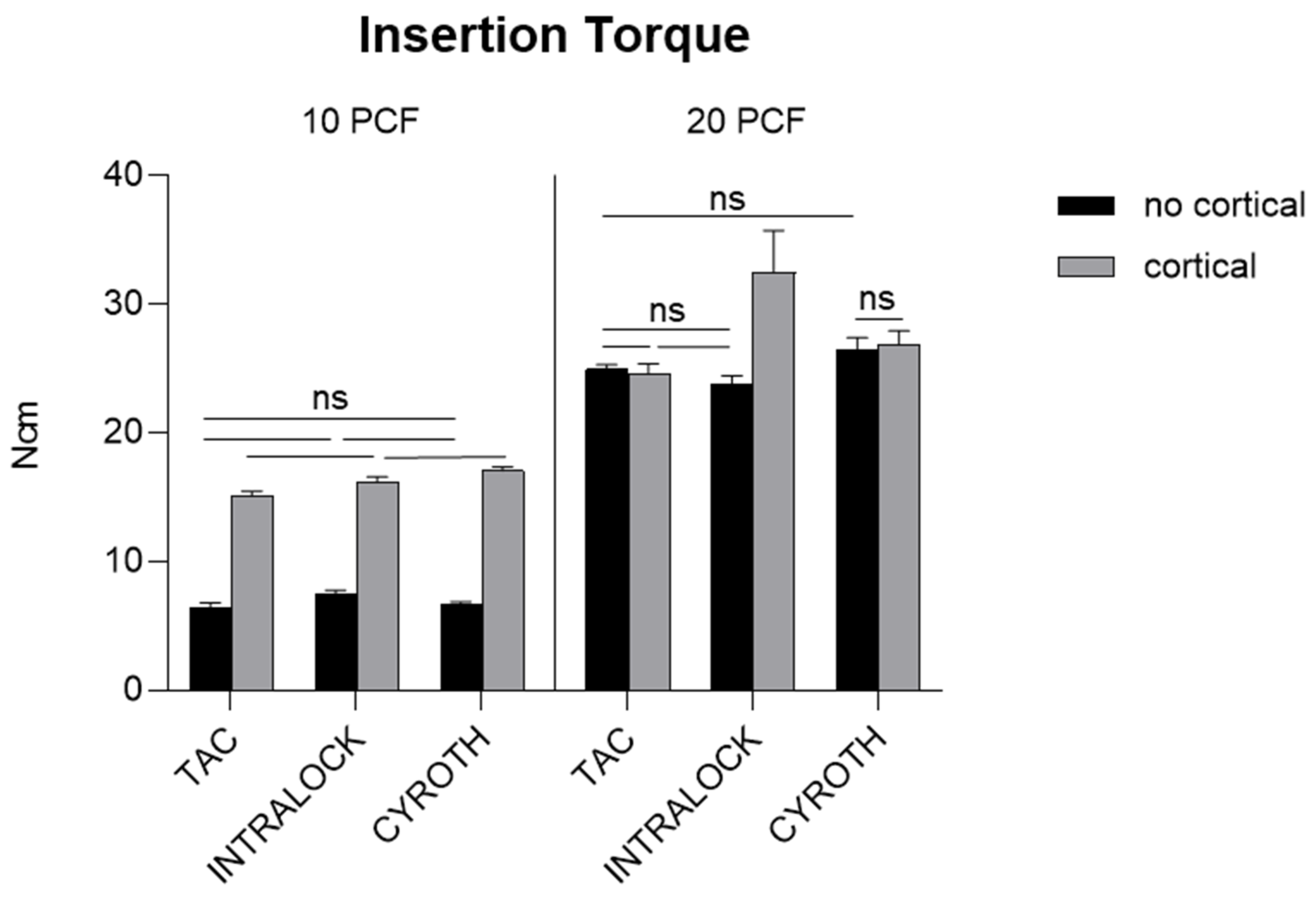
3.1. Insertion Torque Evaluation
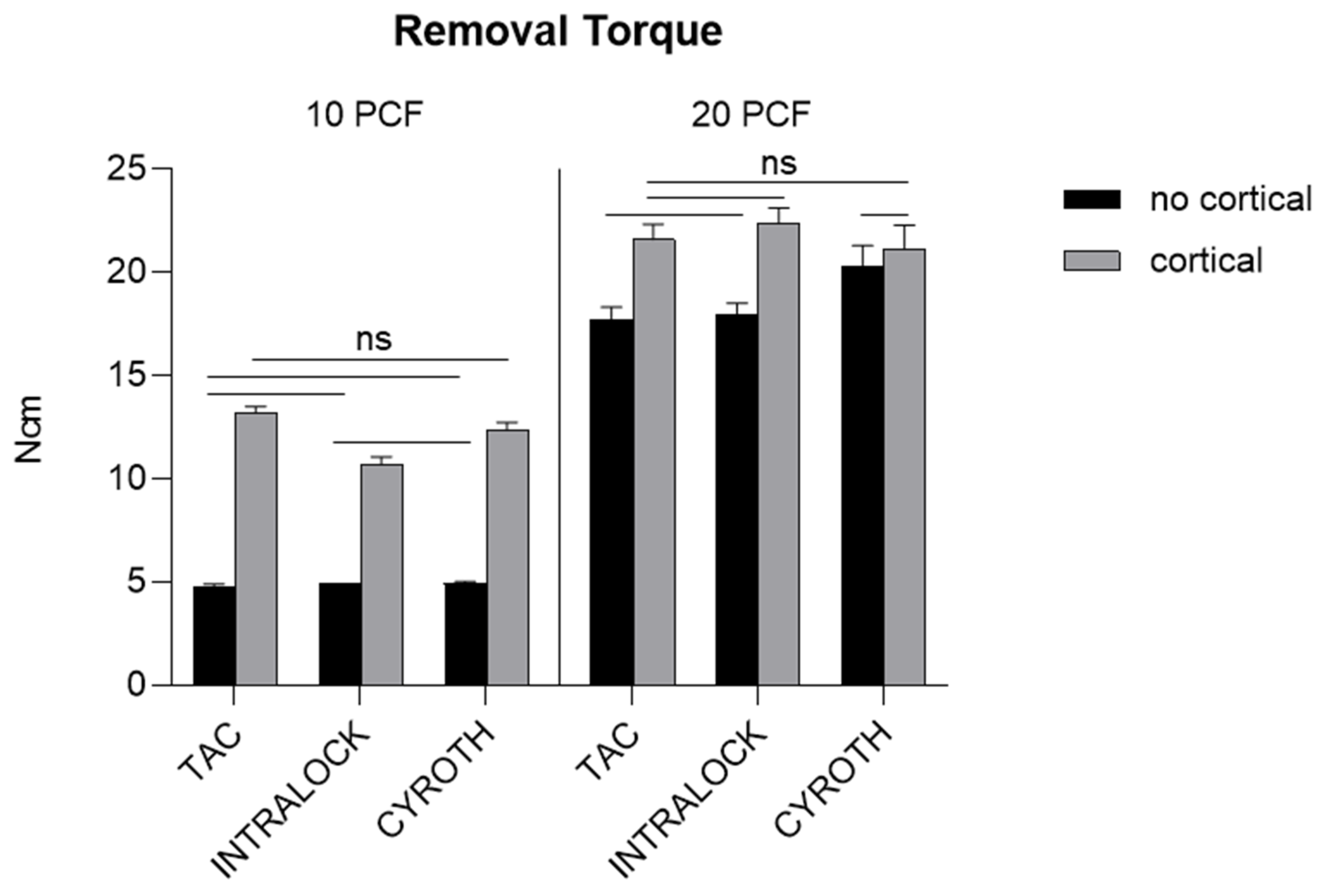
3.2. Removal Torque Evaluation
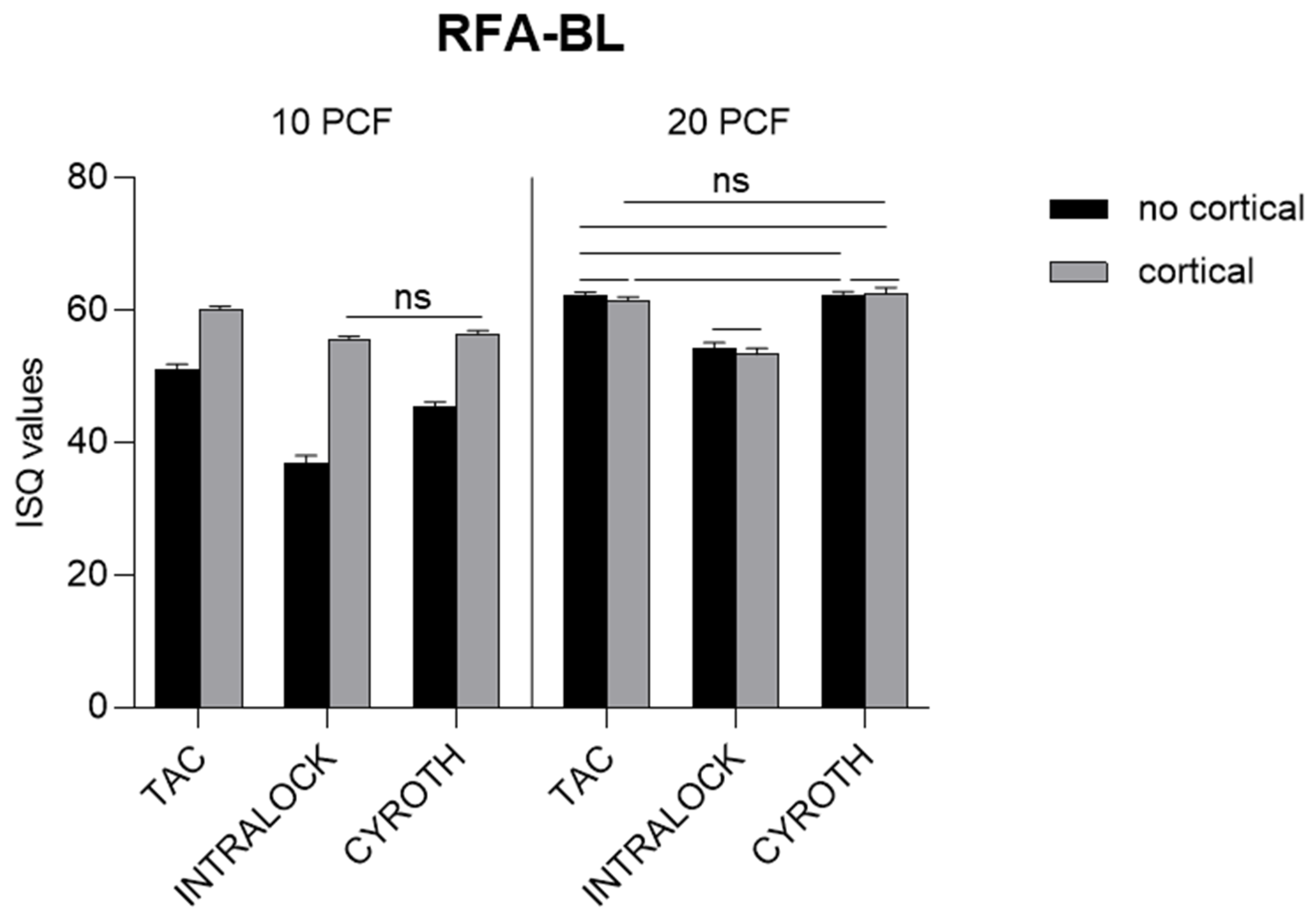
3.3. Resonance Frequency Analysis Evaluation
4. Discussion
5. Conclusions
Author Contributions
Funding
Institutional Review Board Statement
Informed Consent Statement
Data Availability Statement
Acknowledgments
Conflicts of Interest
References
- Gautam, S.; Bhatnagar, D.; Bansal, D.; Batra, H.; Goyal, N. Recent Advancements in Nanomaterials for Biomedical Implants. Biomed. Eng. Adv. 2022, 3, 100029. [Google Scholar] [CrossRef]
- Araújo, M.G.; Silva, C.O.; Souza, A.B.; Sukekava, F. Socket Healing with and without Immediate Implant Placement. Periodontology 2000 2019, 79, 168–177. [Google Scholar] [CrossRef]
- Dhami, B.; Shrestha, P.; Gupta, S.; Pandey, N. Immediate Implant Placement: Current Concepts. J. Nepal. Soc. Periodontol. Oral Implantol. 2019, 3, 18–24. [Google Scholar] [CrossRef]
- Schulte, W.; Heimke, G. The Tübinger Immediate Implant. Quintessenz 1976, 27, 17–23. [Google Scholar] [PubMed]
- Buser, D.; Chappuis, V.; Belser, U.C.; Chen, S. Implant Placement Post Extraction in Esthetic Single Tooth Sites: When Immediate, When Early, When Late? Periodontology 2000 2017, 73, 84–102. [Google Scholar] [CrossRef]
- Mura, P. Immediate Loading of Tapered Implants Placed in Postextraction Sockets: Retrospective Analysis of the 5-year Clinical Outcome. Clin. Implant Dent. Relat. Res. 2012, 14, 565–574. [Google Scholar] [CrossRef]
- Han, C.-H.; Mangano, F.; Mortellaro, C.; Park, K.-B. Immediate Loading of Tapered Implants Placed in Postextraction Sockets and Healed Sites. J. Craniofac. Surg. 2016, 27, 1220–1227. [Google Scholar] [CrossRef]
- Mello, C.C.; Lemos, C.A.A.; Verri, F.R.; Dos Santos, D.M.; Goiato, M.C.; Pellizzer, E.P. Immediate Implant Placement into Fresh Extraction Sockets versus Delayed Implants into Healed Sockets: A Systematic Review and Meta-Analysis. Int. J. Oral Maxillofac. Surg. 2017, 46, 1162–1177. [Google Scholar] [CrossRef]
- Yu, X.; Teng, F.; Zhao, A.; Wu, Y.; Yu, D. Effects of Post-Extraction Alveolar Ridge Preservation versus Immediate Implant Placement: A Systematic Review and Meta-Analysis. J. Evid. Based. Dent. Pract. 2022, 22, 101734. [Google Scholar] [CrossRef]
- Chappuis, V.; Araújo, M.G.; Buser, D. Clinical Relevance of Dimensional Bone and Soft Tissue Alterations Post-extraction in Esthetic Sites. Periodontology 2000 2017, 73, 73–83. [Google Scholar] [CrossRef]
- Romasco, T.; Tumedei, M.; Inchingolo, F.; Pignatelli, P.; Montesani, L.; Iezzi, G.; Petrini, M.; Piattelli, A.; Di Pietro, N. A Narrative Review on the Effectiveness of Bone Regen-eration Procedures with OsteoBiol® Collagenated Porcine Grafts: The Translational Research Experience over 20 Years. J. Funct. Biomater. 2022, 13, 121. [Google Scholar] [CrossRef]
- ASTM F-1839-08; Standard Specification for Rigid Polyurethane Foam for Use as a Standard Material for Testing Orthopedic Devices and Instruments. ASTM International: West Conshohocken, PA, USA, 2021.
- Arosio, P.; Arosio, F.; Di Stefano, D.A. Implant Diameter, Length, and the Insertion Torque/Depth Integral: A Study Using Polyurethane Foam Blocks. Dent. J. 2020, 8, 56. [Google Scholar] [CrossRef] [PubMed]
- Tsolaki, I.N.; Tonsekar, P.P.; Najafi, B.; Drew, H.J.; Sullivan, A.J.; Petrov, S.D. Comparison of Osteotome and Conventional Drilling Techniques for Primary Implant Stability: An In Vitro Study. J. Oral Implant. 2016, 42, 321–325. [Google Scholar] [CrossRef] [PubMed]
- Calvert, K.L.; Trumble, K.P.; Webster, T.J.; Kirkpatrick, L.A. Characterization of Commercial Rigid Polyurethane Foams Used as Bone Analogs for Implant Testing. J. Mater. Sci. Mater. Med. 2010, 21, 1453–1461. [Google Scholar] [CrossRef]
- Nagaraja, S.; Palepu, V. Comparisons of Anterior Plate Screw Pullout Strength Between Polyurethane Foams and Thora-columbar Cadaveric Vertebrae. J. Biomech. Eng. 2016, 138, 104505. [Google Scholar] [CrossRef] [PubMed]
- Gehrke, S.A.; Guirado, J.L.C.; Bettach, R.; Fabbro, M.D.; Martínez, C.P.-A.; Shibli, J.A. Evaluation of the insertion torque, implant stability quotient and drilled hole quality for different drill design: An in vitro Investigation. Clin. Oral Implants Res. 2018, 29, 656–662. [Google Scholar] [CrossRef] [PubMed]
- Romanos, G.E.; Delgado-Ruiz, R.A.; Sacks, D.; Calvo-Guirado, J.L. Influence of the implant diameter and bone quality on the primary stability of porous tantalum trabecular metal dental implants: An in vitro biomechanical study. Clin. Oral Implants Res. 2018, 29, 649–655. [Google Scholar] [CrossRef]
- Comuzzi, L.; Tumedei, M.; Covani, U.; Romasco, T.; Petrini, M.; Montesani, L.; Piattelli, A.; Di Pietro, N. Primary Stability Assessment of Conical Implants in Under-Prepared Sites: An In Vitro Study in Low-Density Polyurethane Foams. Appl. Sci. 2023, 13, 6041. [Google Scholar] [CrossRef]
- Misch, C.E. Bone density: A key determinant for clinical success. Contemp. Implant. Dent. 1999, 8, 109–111. [Google Scholar]
- Romanos, G.; Damouras, M.; Veis, A.A.; Hess, P.; Schwarz, F.; Brandt, S. Comparison of histomorphometry and microradiography of different implant designs to assess primary implant stability. Clin. Implant Dent. Relat. Res. 2020, 22, 373–379. [Google Scholar] [CrossRef]
- Mirzaie, T.; Rouhi, G.; Mehdi Dehghan, M.; Farzad-Mohajeri, S.; Barikani, H. Dental implants’ stability dependence on rotational speed and feed-rate of drilling: In-vivo and ex-vivo investigations. J. Biomech. 2021, 127, 110696. [Google Scholar] [CrossRef] [PubMed]
- Gehrke, S.A.; Treichel, T.L.E.; Pérez-Díaz, L.; Calvo-Guirado, J.L.; Aramburú Júnior, J.; Mazón, P.; de Aza, P.N. Impact of Different Titanium Implant Thread Designs on Bone Healing: A Biomechanical and Histometric Study with an Animal Model. J. Clin. Med. 2019, 8, 777. [Google Scholar] [CrossRef] [PubMed]
- Kashi, A.; Gupta, B.; Malmstrom, H.; Romanos, G.E. Primary Stability of Implants Placed at Different Angulations in Artificial Bone. Implant Dent. 2015, 24, 92–95. [Google Scholar] [CrossRef] [PubMed]
- Karl, M.; Irastorza-Landa, A. Does Implant Design Affect Primary Stability in Extraction Sites. Quintessence Int. 2017, 48, 219–224. [Google Scholar] [CrossRef]
- Yim, H.; Lim, H.-C.; Hong, J.-Y.; Shin, S.-I.; Chung, J.-H.; Herr, Y.; Shin, S.-Y. Primary Stability of Implants with Peri-Implant Bone Defects of Various Widths: An in Vitro Investigation. J. Periodontal Implant Sci. 2019, 49, 39–46. [Google Scholar] [CrossRef]
- Hollensteiner, M.; Fürst, D.; Esterer, B.; Augat, P.; Schrödl, F.; Hunger, S.; Malek, M.; Stephan, D.; Schrempf, A. Novel Bone Surrogates for Cranial Surgery Training. J. Mech. Behav. Biomed. Mater. 2017, 72, 49–51. [Google Scholar] [CrossRef]
- Patel, P.S.; Shepherd, D.E.; Hukins, D.W. Compressive properties of commercially available polyurethane foams as mechanical models for osteoporotic human cancellous bone. BMC Musculoskelet. Disord. 2008, 9, 137. [Google Scholar] [CrossRef]
- Meredith, N.; Alleyne, D.; Cawley, P. Quantitative Determination of the Stability of the Implant-Tissue Interface Using Resonance Frequency Analysis. Clin. Oral Implants Res. 1996, 7, 261–267. [Google Scholar] [CrossRef]
- Staedt, H.; Palarie, V.; Staedt, A.; Wolf, J.M.; Lehmann, K.M.; Ottl, P.; Kämmerer, P.W. Primary Stability of Cylindrical and Conical Dental Implants in Relation to Insertion Torque—A Comparative Ex Vivo Evaluation. Implant Dent. 2017, 26, 250–255. [Google Scholar] [CrossRef]
- Dos Santos, M.V.; Elias, C.N.; Cavalcanti Lima, J.H. The Effects of Superficial Roughness and Design on the Primary Stability of Dental Implants. Clin. Implant Dent. Relat. Res. 2011, 13, 215–223. [Google Scholar] [CrossRef]
- Pommer, B.; Hof, M.; Fädler, A.; Gahleitner, A.; Watzek, G.; Watzak, G. Primary implant stability in the atrophic sinus floor of human cadaver maxillae: Impact of residual ridge height, bone density, and implant diameter. Clin. Oral Implants Res. 2014, 25, 109–113. [Google Scholar] [CrossRef] [PubMed]
- Wilson Jr, T.G.; Miller, R.J.; Trushkowsky, R.; Dard, M. Tapered Implants in Dentistry: Revitalizing Concepts with Technology: A Review. Adv. Dent. Res. 2016, 28, 4–9. [Google Scholar] [CrossRef] [PubMed]
- Chu, S.J.; Levin, B.P.; Egbert, N.; Saito, H.; Nevins, M. Use of a Novel Implant with an Inverted Body-Shift and Prosthetic Angle Correction Design for Immediate Tooth Replacement in the Esthetic Zone: A Clinical Case Series. Int. J. Periodontics Restor. Dent. 2021, 41, 195–204. [Google Scholar] [CrossRef] [PubMed]
- Lages, F.S.; Douglas-de Oliveira, D.W.; Costa, F.O. Relationship between implant stability measurements obtained by insertion torque and resonance frequency analysis: A systematic review. Clin. Implant Dent. Relat. Res. 2018, 20, 26–33. [Google Scholar] [CrossRef]
- Comuzzi, L.; Tumedei, M.; Di Pietro, N.; Romasco, T.; Montesani, L.; Piattelli, A.; Covani, U. Are Implant Threads Important for Implant Stability? An In Vitro Study Using Low-Density Polyurethane Sheets. Eng 2023, 4, 1167–1178. [Google Scholar] [CrossRef]


| IT | 10 PCF | 20 PCF | ||||||||||
|---|---|---|---|---|---|---|---|---|---|---|---|---|
| No Cortical | Cortical | No Cortical | Cortical | |||||||||
| TAC | INTRALOCK | CYROTH | TAC | INTRALOCK | CYROTH | TAC | INTRALOCK | CYROTH | TAC | INTRALOCK | CYROTH | |
| Min | 5.90 | 6.90 | 6.50 | 14.70 | 15.70 | 16.60 | 24.50 | 22.50 | 24.50 | 23.50 | 28.40 | 25.50 |
| Max | 6.90 | 7.80 | 6.90 | 15.70 | 16.70 | 17.60 | 25.50 | 24.50 | 27.40 | 25.50 | 37.20 | 28.40 |
| Mean | 6.39 | 7.44 | 6.73 | 15.16 | 16.23 | 17.06 | 24.93 | 23.83 | 26.42 | 24.63 | 32.44 | 26.87 |
| SD (±) | 0.41 | 0.34 | 0.16 | 0.30 | 0.36 | 0.30 | 0.34 | 0.59 | 0.96 | 0.72 | 3.28 | 1.04 |
| RT | 10 PCF | 20 PCF | ||||||||||
| No Cortical | Cortical | No Cortical | Cortical | |||||||||
| TAC | INTRALOCK | CYROTH | TAC | INTRALOCK | CYROTH | TAC | INTRALOCK | CYROTH | TAC | INTRALOCK | CYROTH | |
| Min | 4.70 | 4.90 | 4.80 | 12.70 | 10.00 | 12.00 | 16.60 | 16.90 | 18.60 | 20.50 | 21.50 | 19.70 |
| Max | 4.90 | 4.90 | 5.10 | 13.70 | 11.00 | 13.00 | 18.60 | 18.60 | 21.50 | 22.50 | 23.50 | 22.50 |
| Mean | 4.81 | 4.90 | 4.95 | 13.20 | 10.72 | 12.40 | 17.70 | 17.94 | 20.33 | 21.60 | 22.41 | 21.15 |
| SD (±) | 0.10 | 0.00 | 0.08 | 0.31 | 0.36 | 0.34 | 0.63 | 0.57 | 0.98 | 0.75 | 0.72 | 1.14 |
| RFA—BL | 10 PCF | 20 PCF | ||||||||||
| No Cortical | Cortical | No Cortical | Cortical | |||||||||
| TAC | INTRALOCK | CYROTH | TAC | INTRALOCK | CYROTH | TAC | INTRALOCK | CYROTH | TAC | INTRALOCK | CYROTH | |
| Min | 50.00 | 35.00 | 44.00 | 60.00 | 55.00 | 56.00 | 62.00 | 53.00 | 61.00 | 61.00 | 52.00 | 62.00 |
| Max | 52.00 | 38.00 | 46.00 | 61.00 | 56.00 | 57.00 | 63.00 | 55.00 | 63.00 | 62.00 | 55.00 | 64.00 |
| Mean | 51.00 | 36.80 | 45.40 | 60.20 | 55.50 | 56.40 | 62.30 | 54.20 | 62.20 | 61.50 | 53.30 | 62.60 |
| SD (±) | 0.82 | 1.23 | 0.70 | 0.42 | 0.53 | 0.52 | 0.48 | 0.92 | 0.63 | 0.53 | 0.95 | 0.84 |
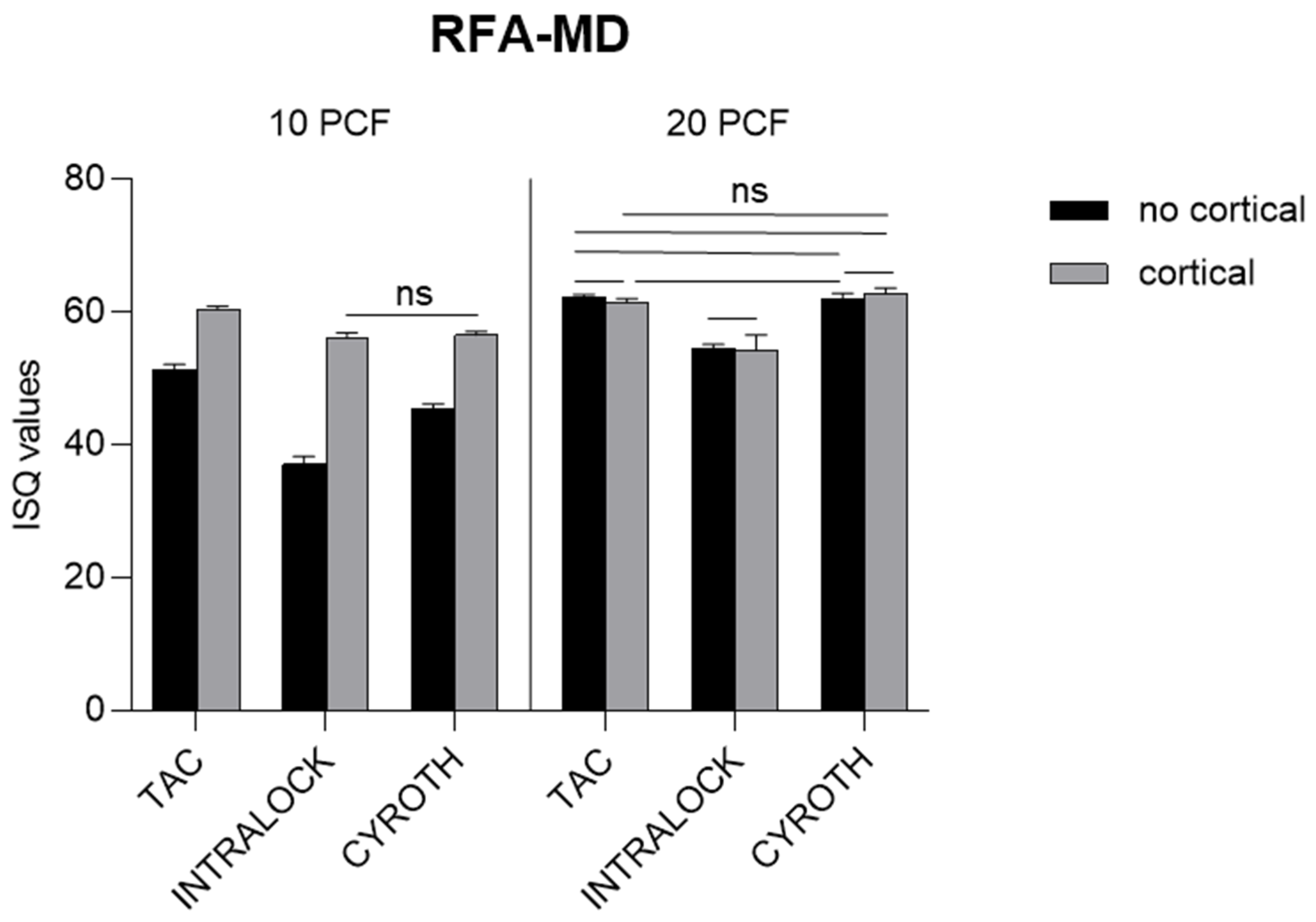
| RFA—MD | 10 PCF | 20 PCF | ||||||||||
| No Cortical | Cortical | No Cortical | Cortical | |||||||||
| TAC | INTRALOCK | CYROTH | TAC | INTRALOCK | CYROTH | TAC | INTRALOCK | CYROTH | TAC | INTRALOCK | CYROTH | |
| Min | 50.00 | 35.00 | 44.00 | 60.00 | 55.00 | 56.00 | 62.00 | 53.00 | 61.00 | 61.00 | 52.00 | 62.00 |
| Max | 52.00 | 38.00 | 46.00 | 61.00 | 57.00 | 57.00 | 63.00 | 55.00 | 63.00 | 62.00 | 58.00 | 64.00 |
| Mean | 51.20 | 37.00 | 45.30 | 60.40 | 56.00 | 56.50 | 62.20 | 54.40 | 62.10 | 61.50 | 54.30 | 62.90 |
| SD (±) | 0.92 | 1.25 | 0.82 | 0.52 | 0.82 | 0.53 | 0.42 | 0.70 | 0.74 | 0.53 | 2.21 | 0.74 |
Disclaimer/Publisher’s Note: The statements, opinions and data contained in all publications are solely those of the individual author(s) and contributor(s) and not of MDPI and/or the editor(s). MDPI and/or the editor(s) disclaim responsibility for any injury to people or property resulting from any ideas, methods, instructions or products referred to in the content. |
© 2023 by the authors. Licensee MDPI, Basel, Switzerland. This article is an open access article distributed under the terms and conditions of the Creative Commons Attribution (CC BY) license (https://creativecommons.org/licenses/by/4.0/).
Share and Cite
Comuzzi, L.; Tumedei, M.; Di Pietro, N.; Romasco, T.; Heydari Sheikh Hossein, H.; Montesani, L.; Inchingolo, F.; Piattelli, A.; Covani, U. A Comparison of Conical and Cylindrical Implants Inserted in an In Vitro Post-Extraction Model Using Low-Density Polyurethane Foam Blocks. Materials 2023, 16, 5064. https://doi.org/10.3390/ma16145064
Comuzzi L, Tumedei M, Di Pietro N, Romasco T, Heydari Sheikh Hossein H, Montesani L, Inchingolo F, Piattelli A, Covani U. A Comparison of Conical and Cylindrical Implants Inserted in an In Vitro Post-Extraction Model Using Low-Density Polyurethane Foam Blocks. Materials. 2023; 16(14):5064. https://doi.org/10.3390/ma16145064
Chicago/Turabian StyleComuzzi, Luca, Margherita Tumedei, Natalia Di Pietro, Tea Romasco, Hamid Heydari Sheikh Hossein, Lorenzo Montesani, Francesco Inchingolo, Adriano Piattelli, and Ugo Covani. 2023. "A Comparison of Conical and Cylindrical Implants Inserted in an In Vitro Post-Extraction Model Using Low-Density Polyurethane Foam Blocks" Materials 16, no. 14: 5064. https://doi.org/10.3390/ma16145064
APA StyleComuzzi, L., Tumedei, M., Di Pietro, N., Romasco, T., Heydari Sheikh Hossein, H., Montesani, L., Inchingolo, F., Piattelli, A., & Covani, U. (2023). A Comparison of Conical and Cylindrical Implants Inserted in an In Vitro Post-Extraction Model Using Low-Density Polyurethane Foam Blocks. Materials, 16(14), 5064. https://doi.org/10.3390/ma16145064