3.2. Topology Optimisation of Mountain Bike Stem
The NX 12 topology optimisation module enables the control of material distribution throughout the design space. The value of this command is from 0 to 100%. In the case of 100%, the resulting optimisation creates solid parts. In the case of using 0%, the part is modelled with thin truss structures. After several simulation attempts with various percentage settings, it was decided to set a value of 43%. From a design perspective, this value gives great results in a truss cross-section, which is suitable for the SLM manufacturing process. This setting positively affected the resulting internal stresses and the mass of the simulated bike stem.
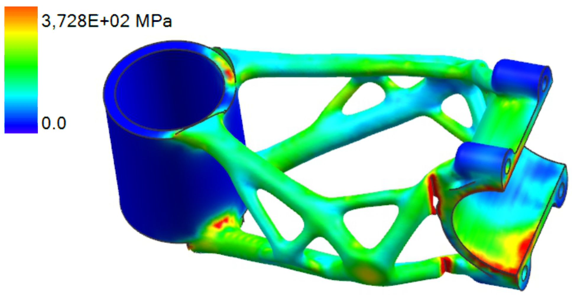
The resulting optimisation, shown in
Figure 7, took 8 h and 10 min to converge. The optimisation algorithm reached a stem weight of 98 g, thus meeting the target weight requirement of 100 g.
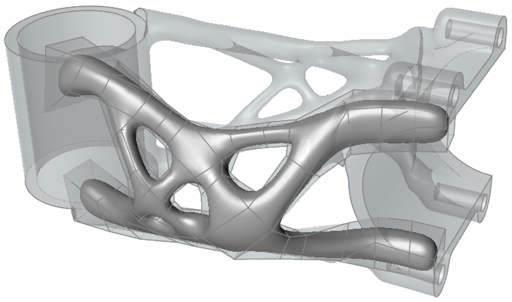
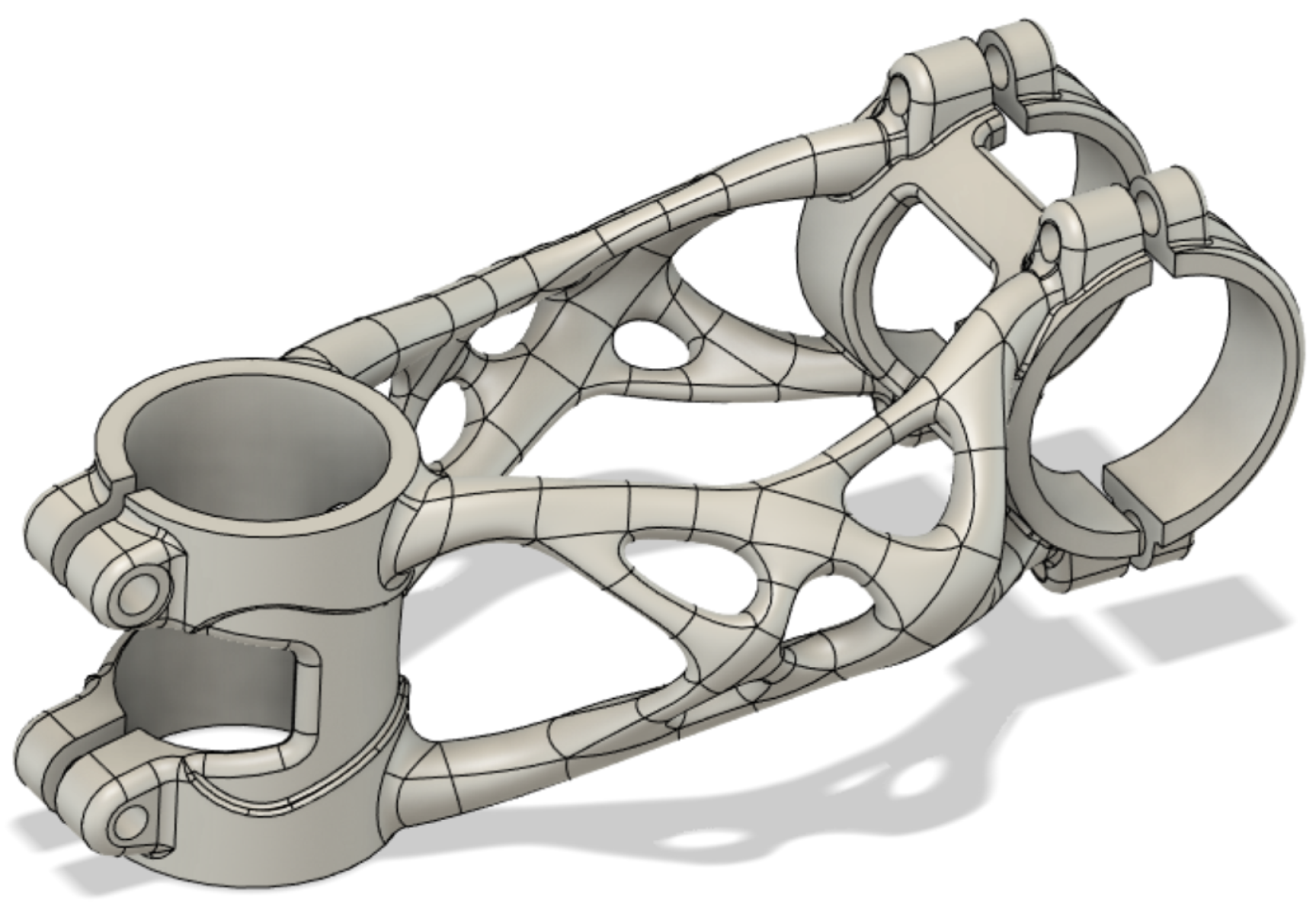
The model, created in the Siemens NX 12 topology optimisation module, contains some imperfections and places where significant stresses have been generated that exceed the strength limit of the material. This is mainly caused by the initial design space shape. For this reason, it was necessary to redesign the shape to a printable state. Altair Inspire 2021.1 (Altair Engineering Inc., Troy, MI, USA) software was used for this step using the Polynurbs function, as shown in
Figure 8. The remaining parts of the design used for clamping the handlebar and head tube were redesigned in Geomagic Desing X 2022.0.0 (3D Systems Corporation, Rock Hill, SC, USA) software. The resulting shape of the mountain bike stem is shown in
Figure 9.
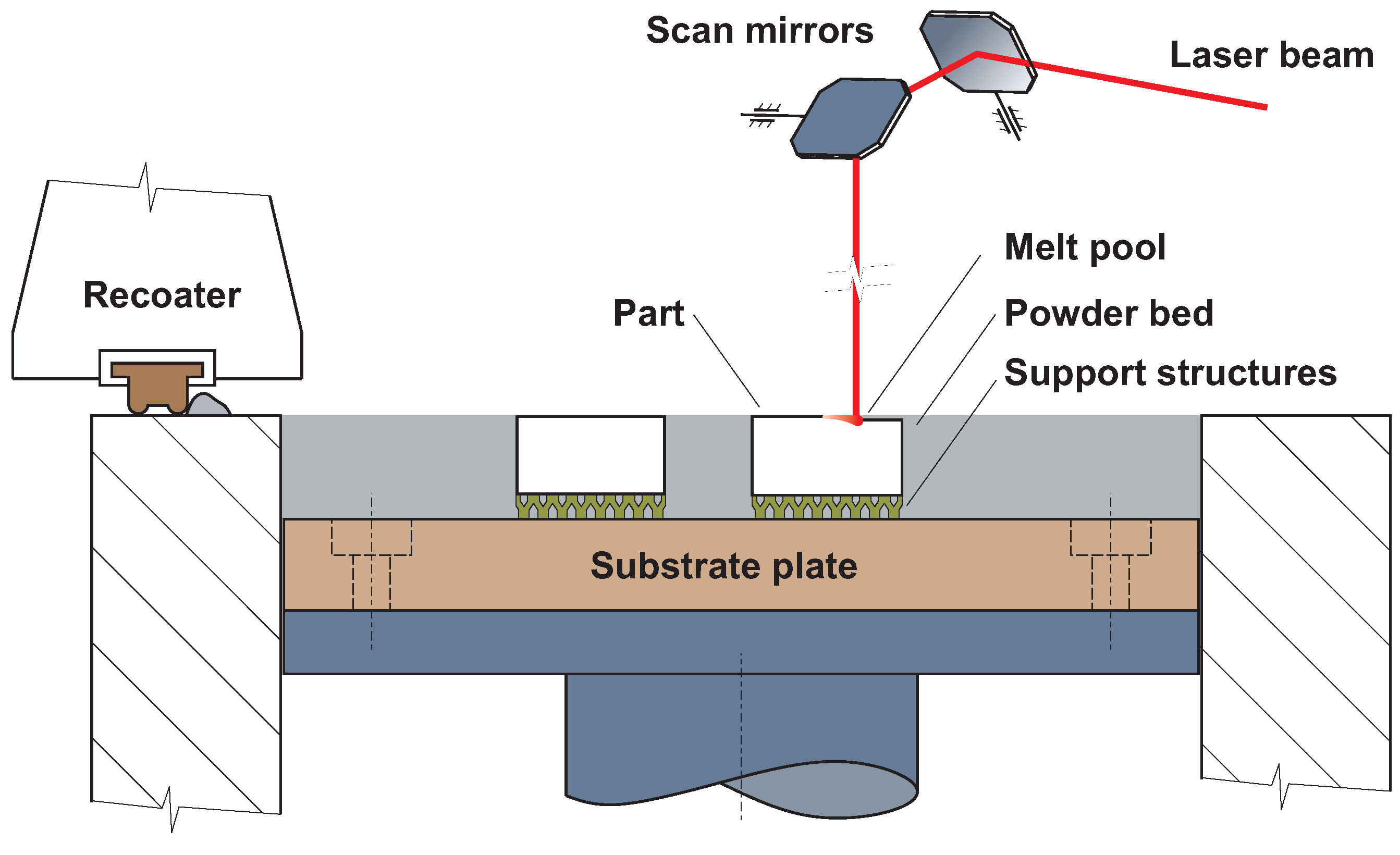
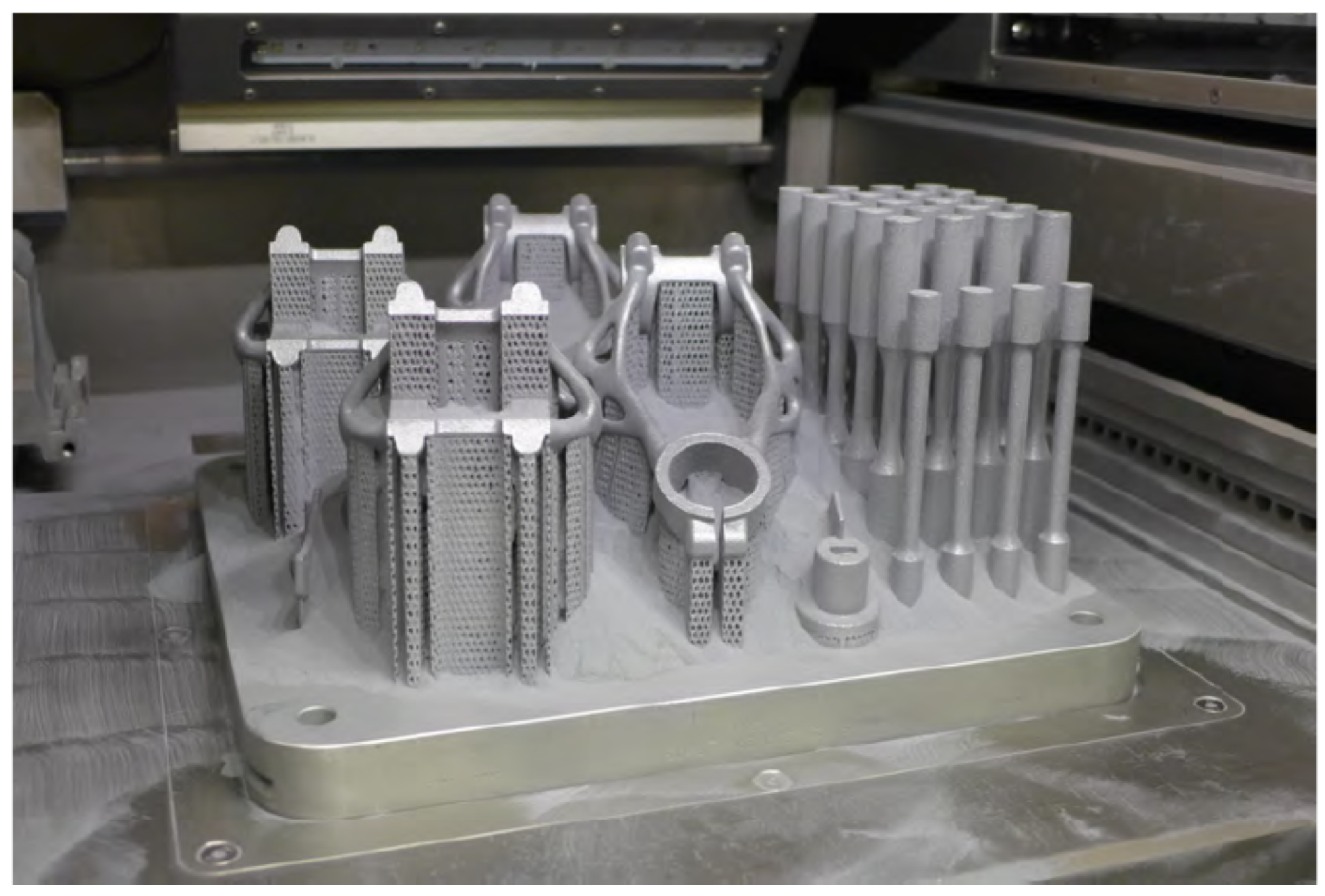
3.4. Fabrication
After the design was verified by FEA simulation, four pieces of bike stems were manufactured (
Figure 17) with the setting of process parameters defined in
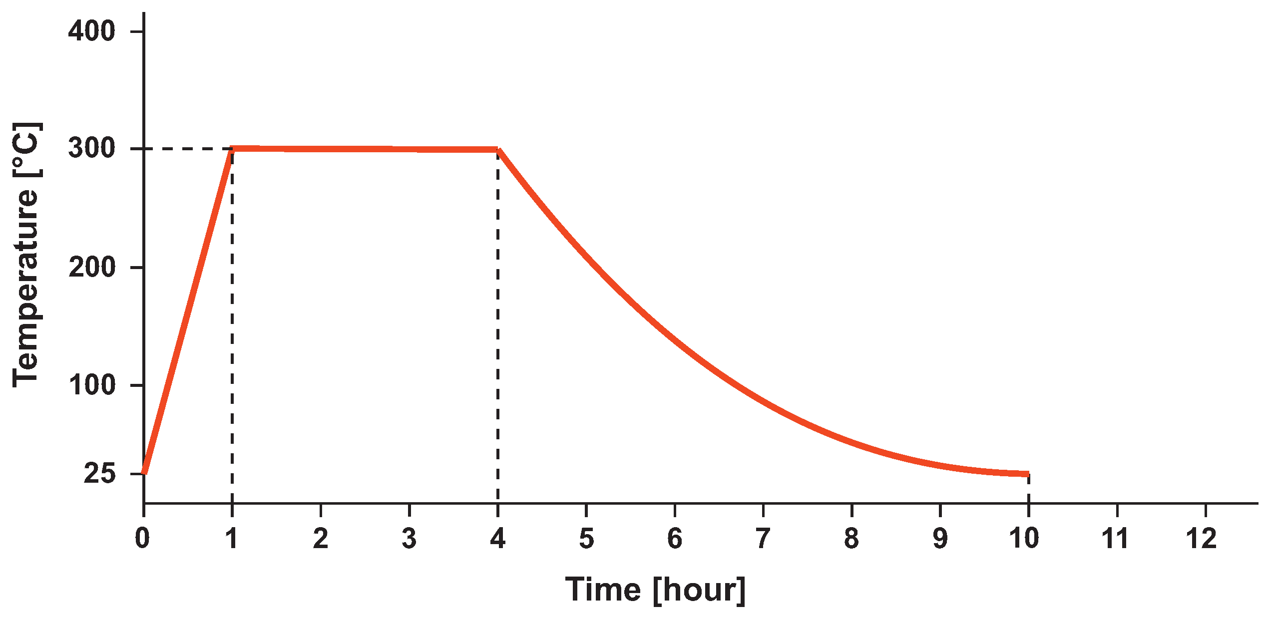
Table 1. Bike stems were printed on an SLM 280HL machine from SLM Solutions Group AG (Lübeck, Germany). The printing process of four pieces of bike stems took 30 h. After printing, the parts were scanned to measure the dimensional accuracy. This was followed by heat treatment, removal of support structures and machining of the seating surfaces.
After the machining of the seating surfaces, the weight measurement of the bike stem was carried out as described in
Table 7. The table shows an average saving of about 7.9% on the body of the bike stem compared to a conventionally manufactured bike stem and 27.87% weight saving on clamps. As the reference, Force Team Spry (KCK Cyklosport-Mode Ltd. Otrokovice, Czech Republic) bike stem was selected with 100 mm length and 6° slope. For weight measurement, RADWAG WTC 600 digital scale (Radwag, Radom, Poland) was used.
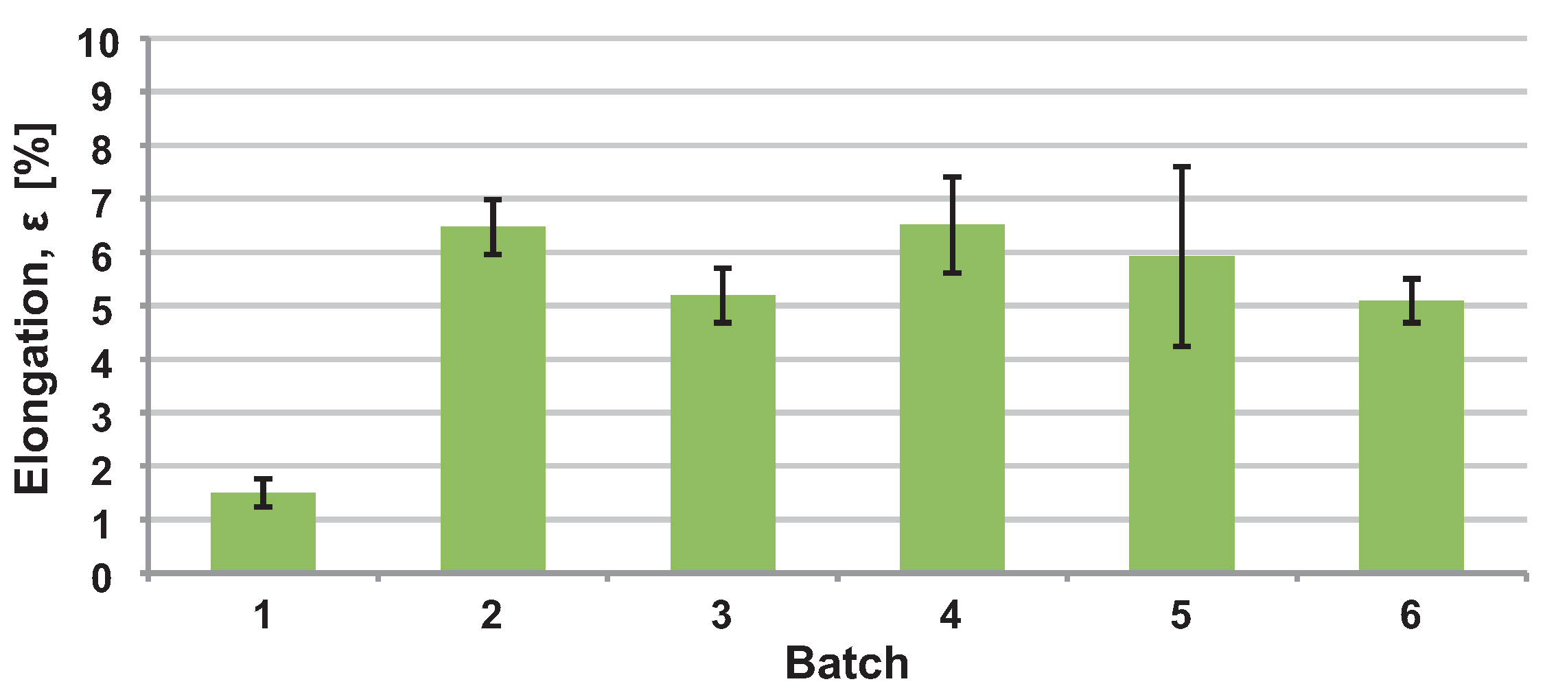
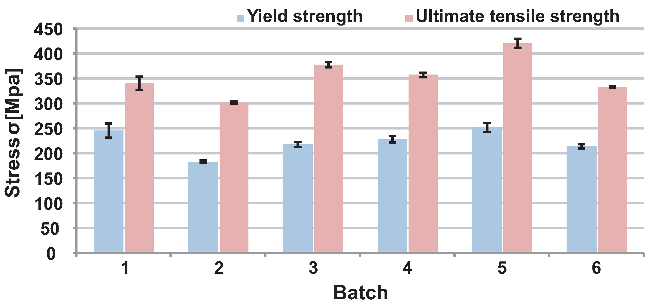
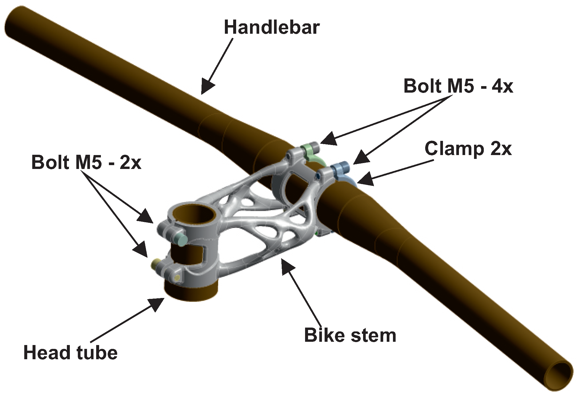
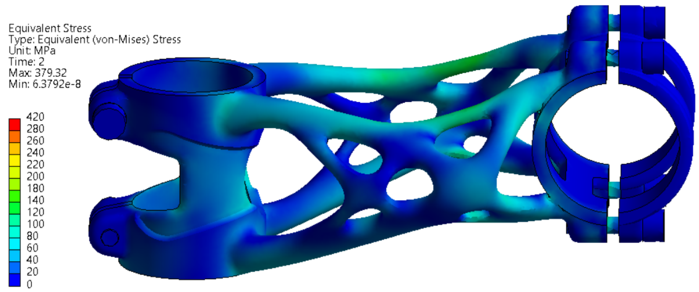
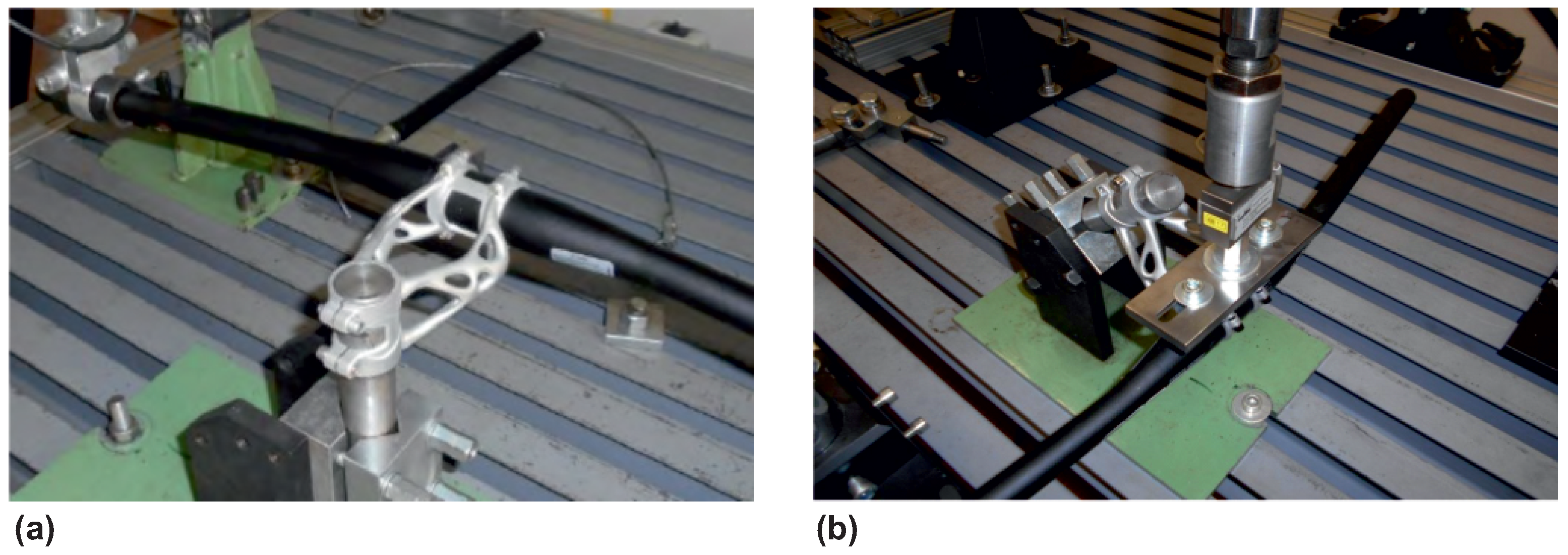
3.5. Experimental Testing of Printed Bike Stems
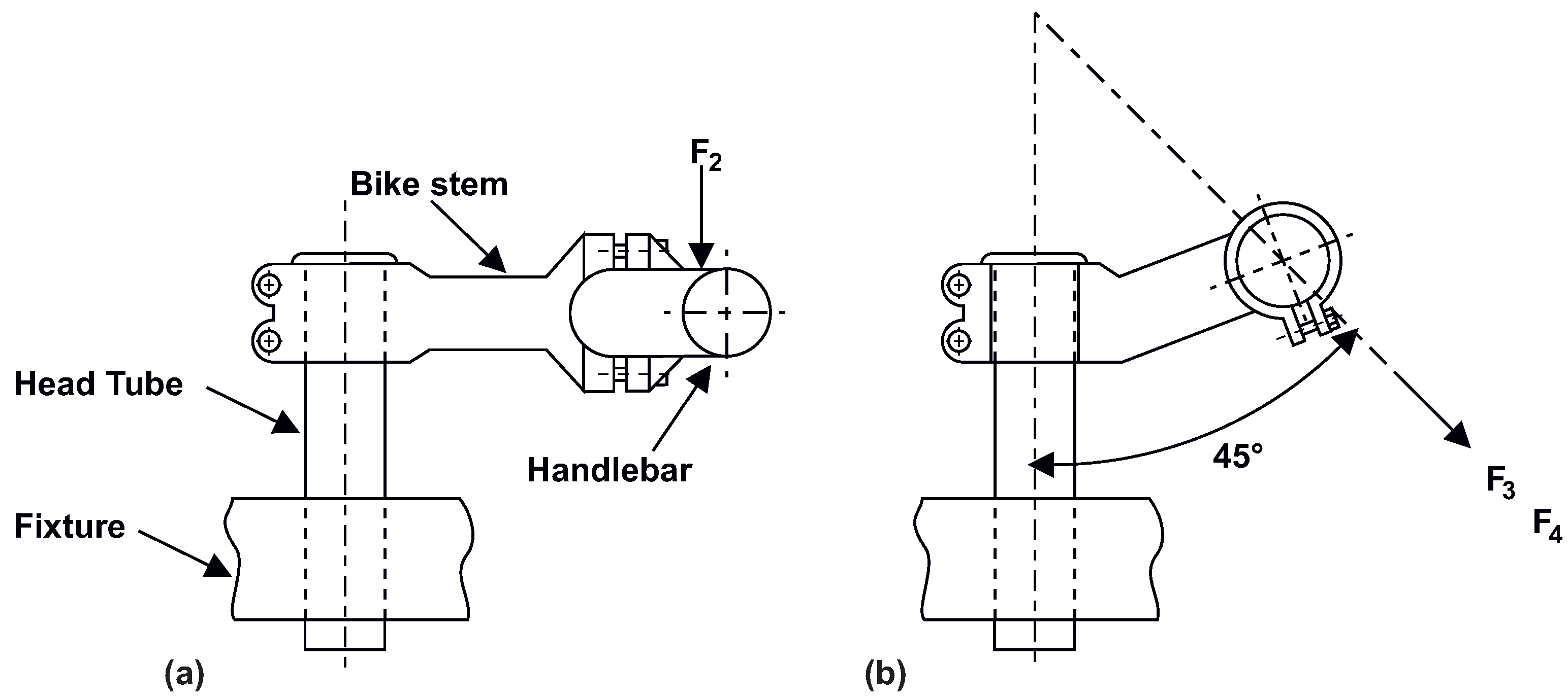
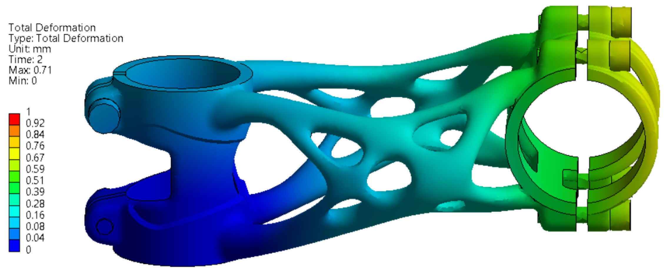
Experimental load tests according to ISO 4210-5 were performed on a test bench as a bike stem and handlebar assembly. The first experiment was a side bend, which is shown in
Figure 18a. The bike stem assembly was attached to a rigid fixture on the head tube seating surface and tightened with M5 bolts by a torque of 5 nm. The force required by the ISO 4210-5 standard was applied through a pneumatic cylinder. The displacement of the handlebar was measured at the point where the force was applied using MarCator 1086R digital indicator (Mahr GmbH, Göttingen, Germany). The resulting measured displacement was 14.72 mm, and it fit into a limit defined by ISO 4210-5 standard.
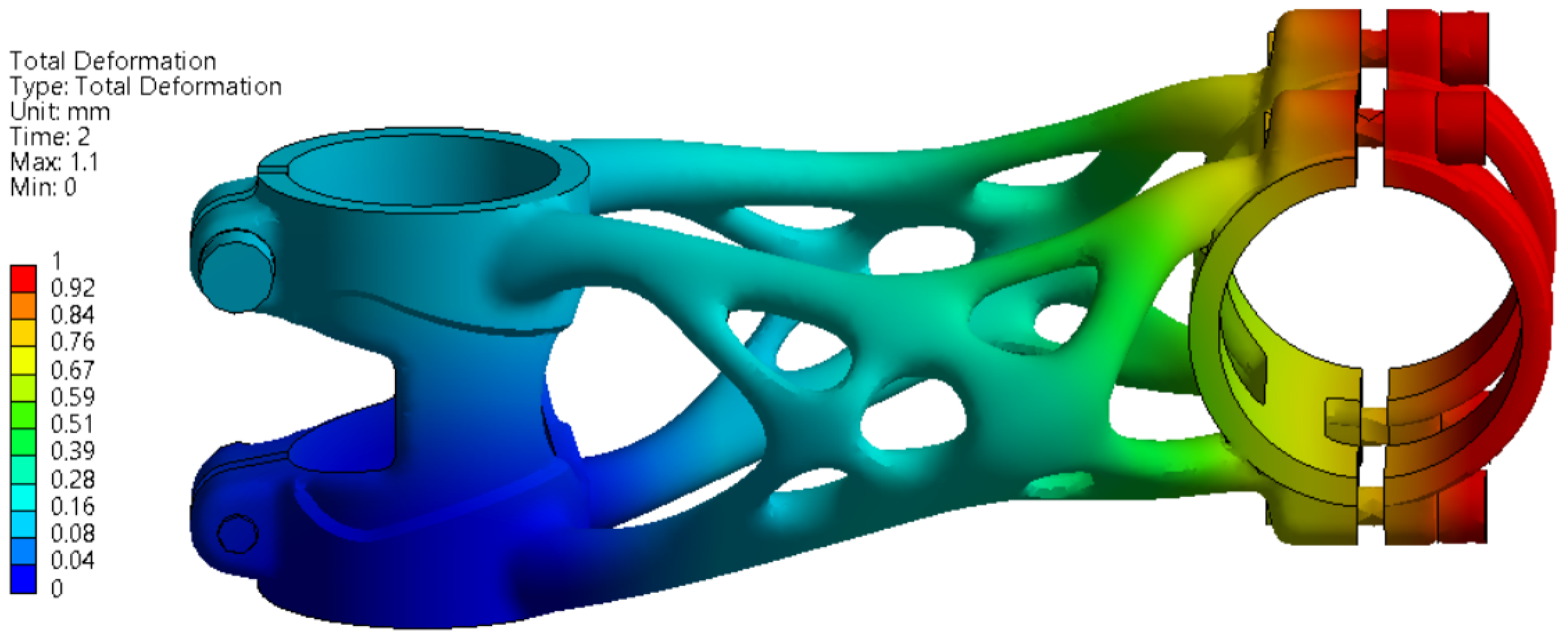
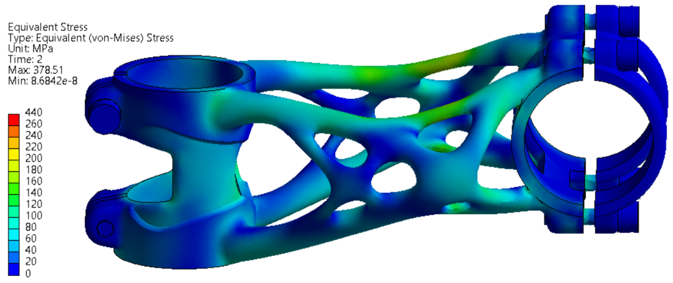
The second experiment was forward bending with a force magnitude of F
= 1600 N. The bike stem position on the testing bench is shown in
Figure 18b. The method of force load and measurement of displacement was realised, similar to the previous experiment. The resulting measured displacement was 0.50 mm and fit into a limit defined by ISO 4210-5. The second level with force magnitude F
= 2600 N generates displacement of 0.92 mm, which again fits into the ISO standard limitation.
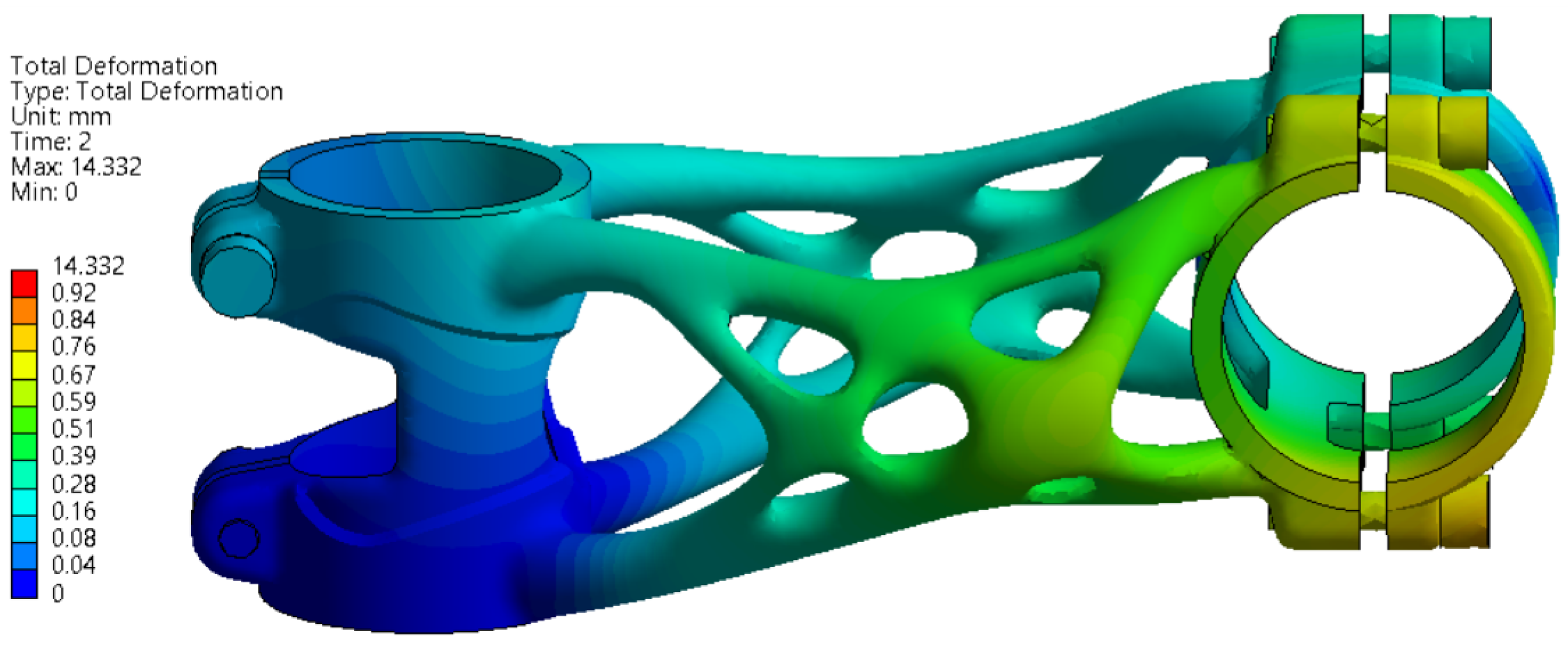
3.6. Measuring the Deformation on Parts
The dimension accuracy analysis was performed on bike stems at each stage of the production process. Two bike stems were used for this shape accuracy analysis. One was left attached to the substrate plate (Version A), and the second was separated from the substrate plate right after the manufacturing process (Version B). Furthermore, two more bike stems were measured after the experiments to map the permanent deformation. For scanning, the optical scanner Range Vision Spectrum (RangeVision CIS, Moscow, Russia) was used. For better accuracy of scanned data, reference points and a rotation table were used.
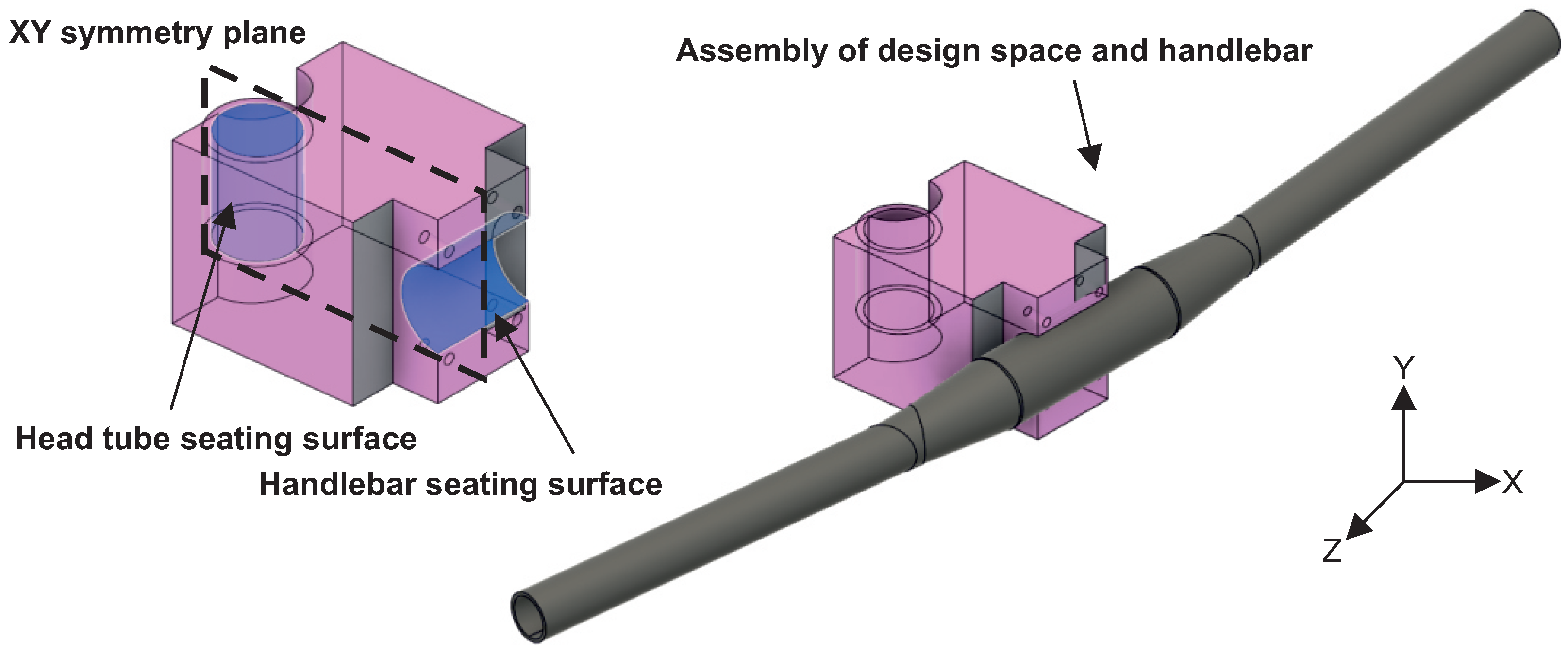
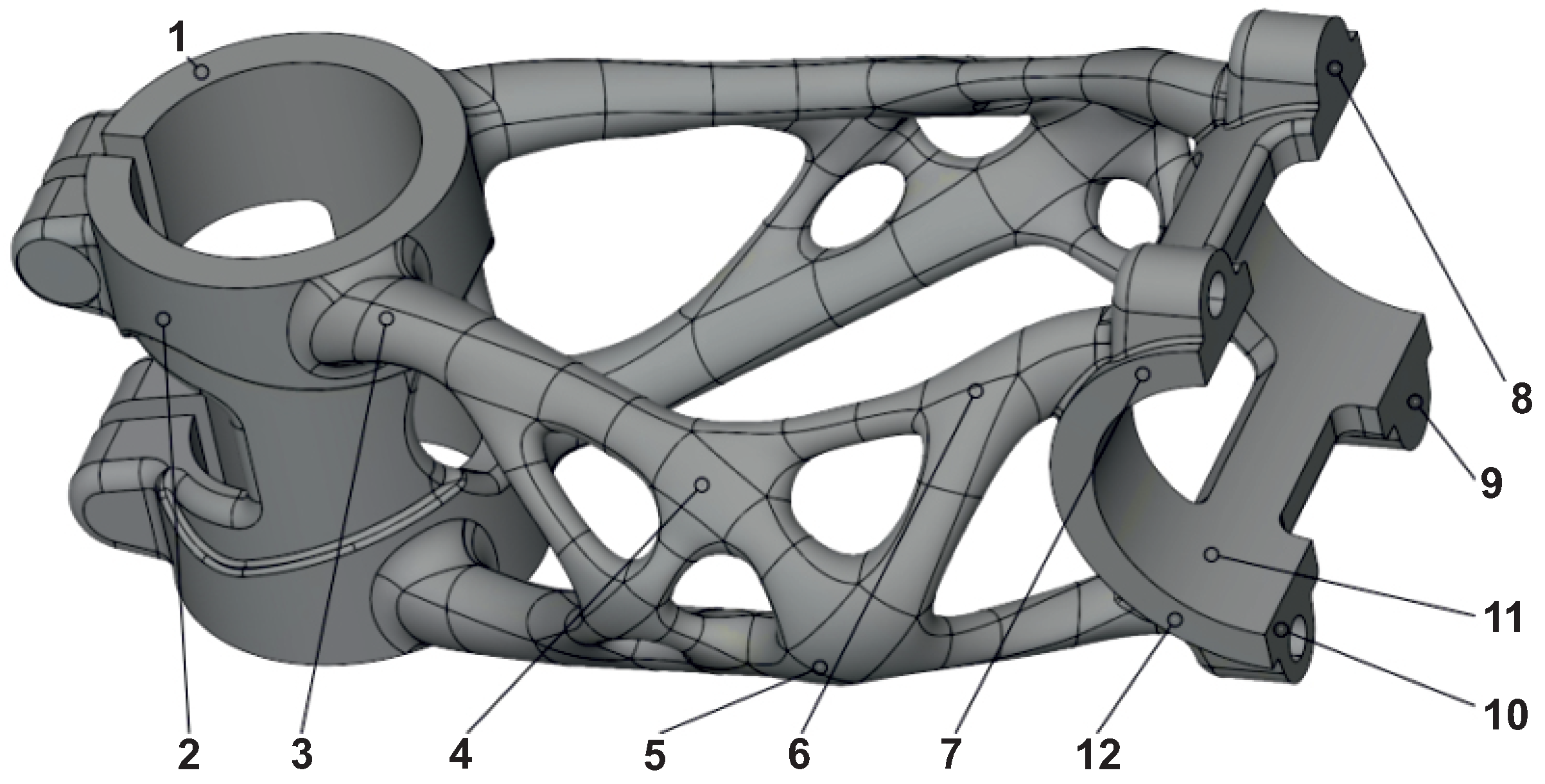
Gom Inspect 2020 (Carl Zeiss AG, Oberkochen, Germany) was used to validate overall deformation. The alignment of scan data on the STEP model was performed by a global best-fit function. On the body of the stem, twelve evaluation points were selected for the comparison of deformation between individual production stages (
Figure 19). These points are located in such areas where no support structures were attached. This ensures that measurements are not influenced by any finishing operations.
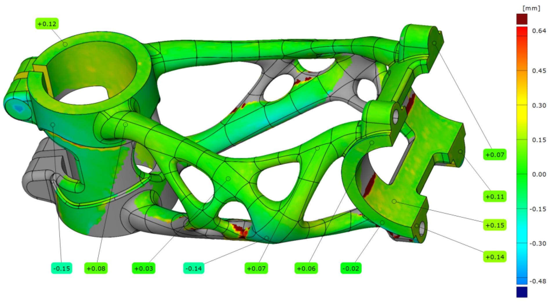
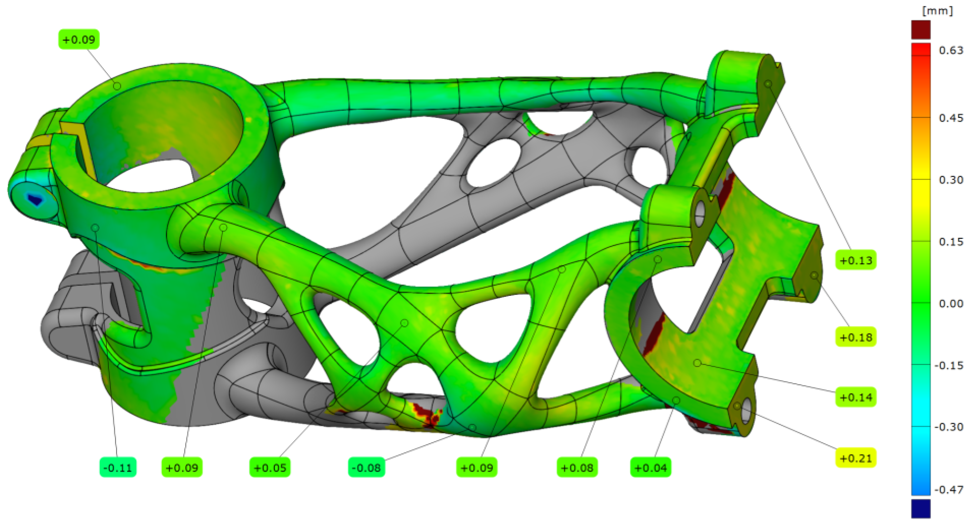
After the manufacturing process, the first bike stem (A1) was scanned on the substrate plate. The bike stem was aligned on step data with a deviation of 0.07 mm. After alignment, dimension accuracy analysis was performed (see
Figure 20).
The summarised data from five measurements with different settings are contained in
Table 8. The measurement after the manufacturing process without any HT shows a maximal deviation of 0.15 mm. The higher deformation occurs in the clamping section of the handlebar and head tube. For this stage, normal deviations in the area of the truss section are in the range of ±0.10 mm.
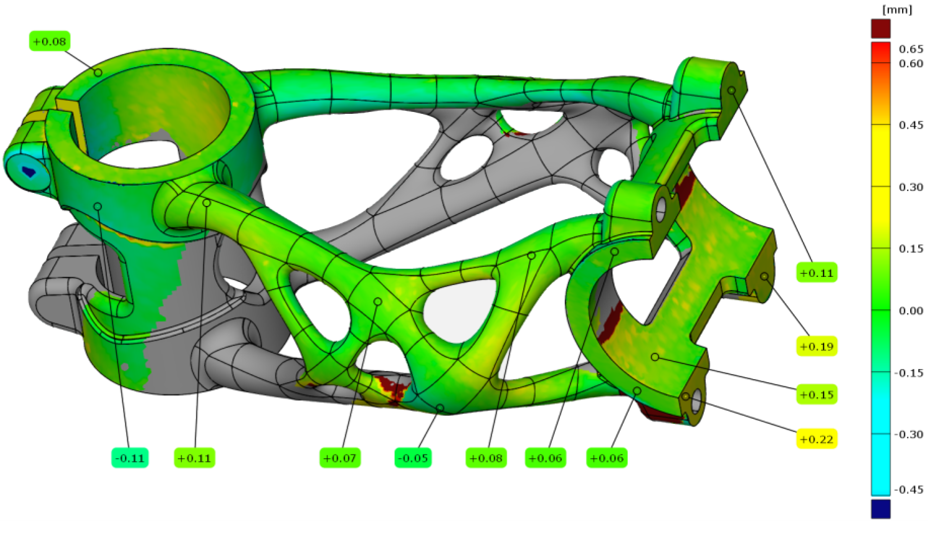
For the second measurement, the bike stem (A2) was still left on the substrate plate, and the HT was performed. The alignment of scanned data on the STEP model was with a deviation of 0.08 mm. The results of the analysis are shown in
Figure 21. The results of measured points are nearly the same in the truss and head tube section. The only higher deviation of 0.21 mm can be found in the handlebar clamping section.
The last measurement of the first bike stem (A3) was after removal from the substrate plate. The results of the analysis are shown in
Figure 22. In this case, the alignment deviation was 0.075 mm, and the measured data are with little deviation from the previous measurements. The maximal deviation still occurs in the handlebar clamping area.
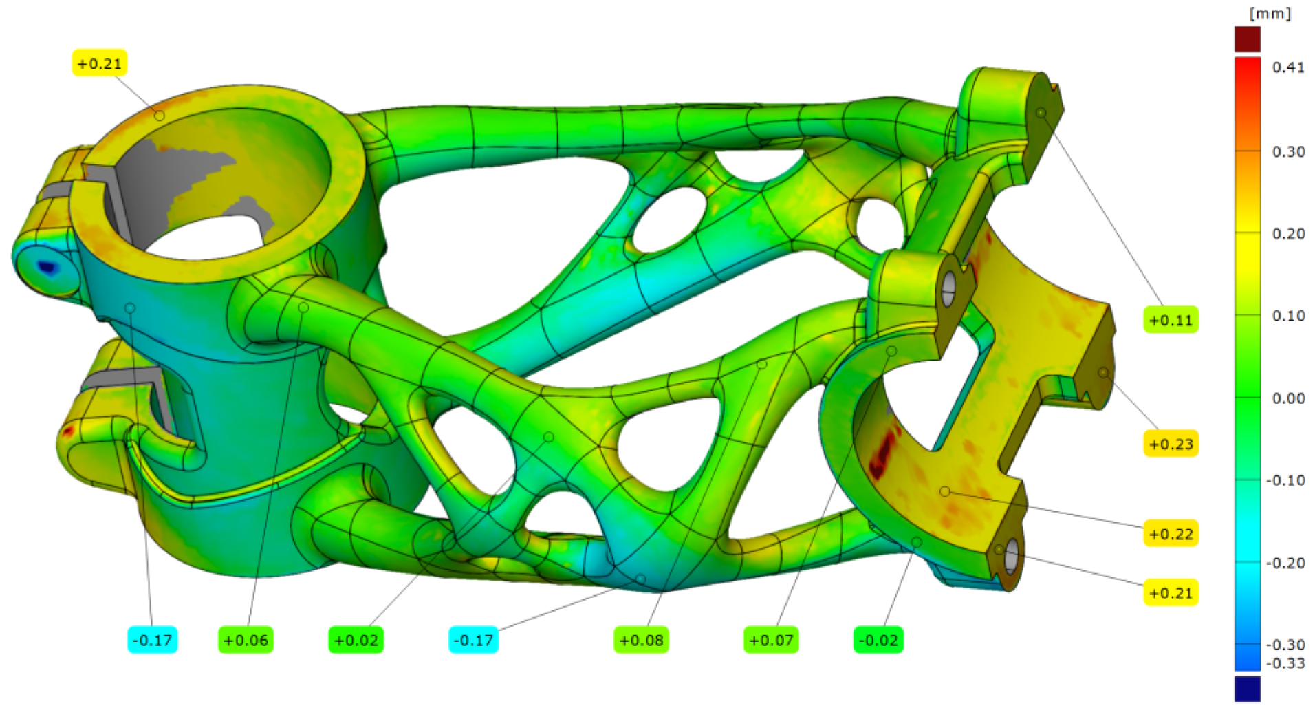
After the manufacturing process, the bike stem (B1) was subtracted from the substrate plate, and the support structures were removed. The bike stem was aligned with the same setting as in previous measurements with a deviation of 0.10 mm. The results from the analysis are shown in
Figure 23, where the maximal deviation is 0.23 mm occurs in the handlebar clamping area.
The truss section also has a higher deviation than what was measured on the bike stem that was left on the substrate plate (A1).
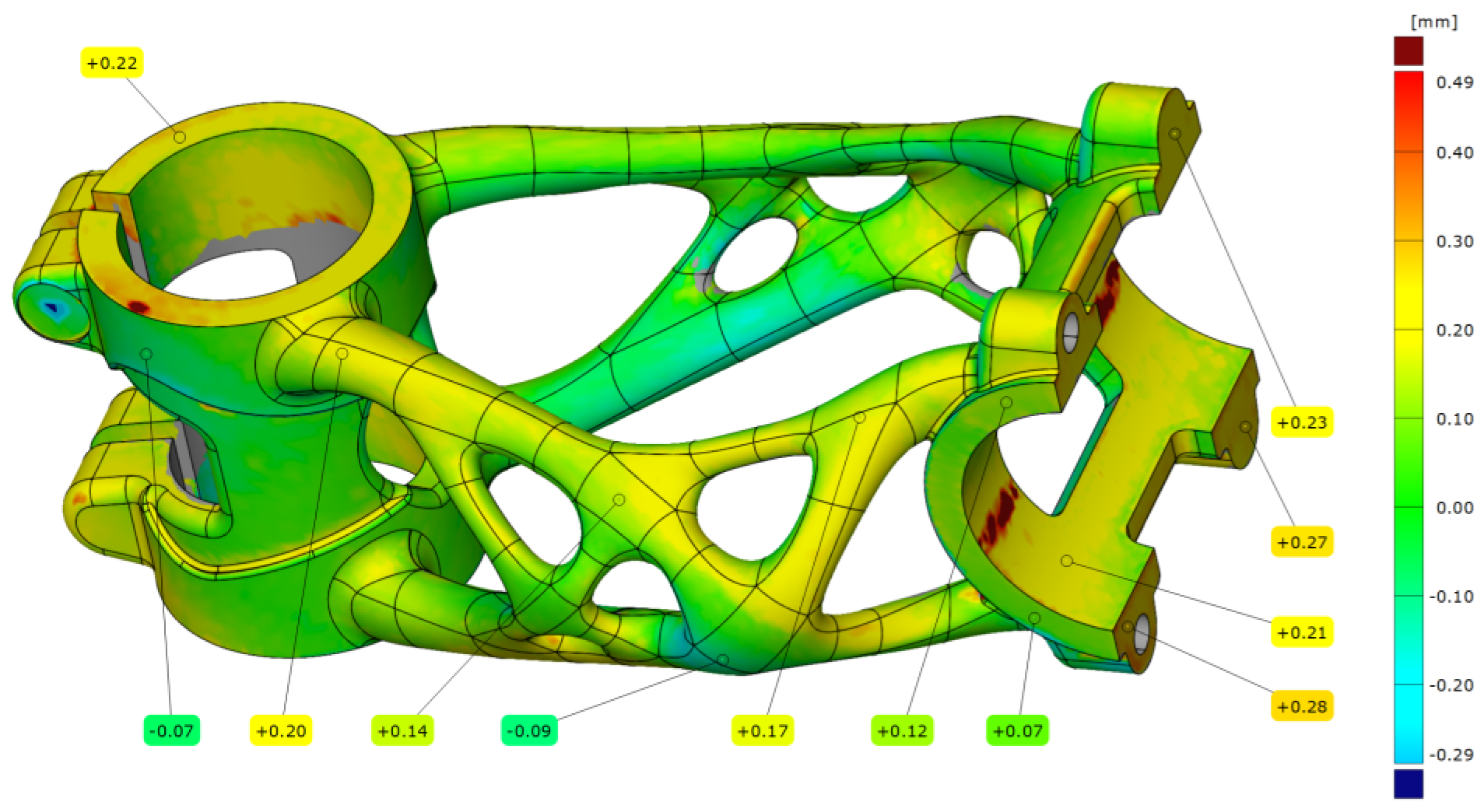
After HT the bike stem (B2) was measured again with a data deviation of 0.07 mm. The results of the analysis are shown in
Figure 24. The maximal deviation is 0.28 mm in the handlebar clamping area.
From all realised measurements is seen a worsening trend of bike stem deviation from nominal data when the bike stem is removed from the substrate plate before HT. It is suitable to leave parts on the substrate plate during HT, and it leads to better dimensional accuracy than if the bike stem is removed before HT.
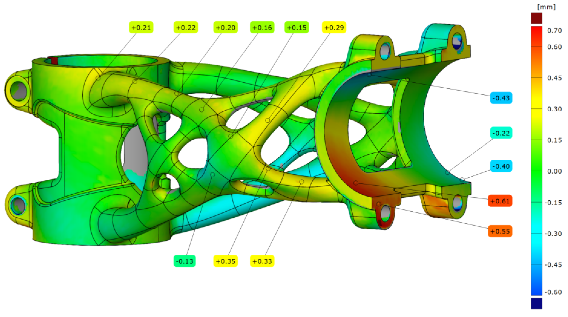
In the last step, the bike stems after experiments were analysed. It was necessary to evaluate the permanent deformation on the part. The first evaluated bike stem was after the side bending experiment. The scanned mesh was aligned on STEP data with a deviation of 0.14 mm. The analysis of permanent deformation is shown in
Figure 25 where the maximal deviation in the handlebar clamping area is 0.61 mm. Also, the truss section was influenced by applied force, and the deviation is around 0.3 mm. This permanent deformation was produced when the yield strength of the material was exceeded during the experiment.
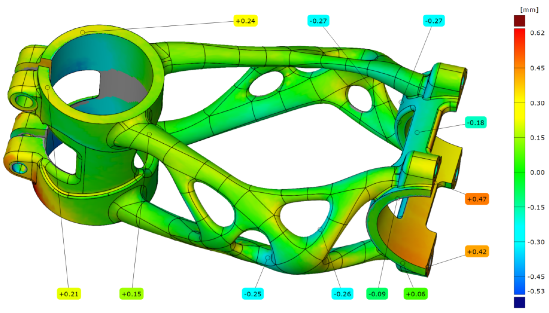
The scanned data of the bike stem after forward bending were aligned with a deviation of 0.13 mm. The results shown in
Figure 26 correspond to the second level of forward bending with force F
= 2600 N. The maximal deviation that occurs on the bike stem is 0.47 mm and is located in the handlebar clamping area.
The outcomes from the analysis show that even after passing these two experiments, the bike stem is suitable for further use.


