

Application of Functionally Graded Shell Lattice as Infill in Additive Manufacturing


Abstract
1. Introduction
- How to represent the geometry of a 3D printed object with a functionally graded infill efficiently?
- How to identify an optimal design among many viable options, and how to include manufacturing constraints?
- Does the developed part fulfil functional requirements?
- How to validate its structural performance theoretically?
- Is manufacturing the part with a functionally graded infill feasible with the metal FFF technology?
1.1. Lightweight Constructions
1.2. Additive Manufacturing
1.3. Infill as Functionally Graded Structure
1.4. Design Exploration
1.5. Lattice Types
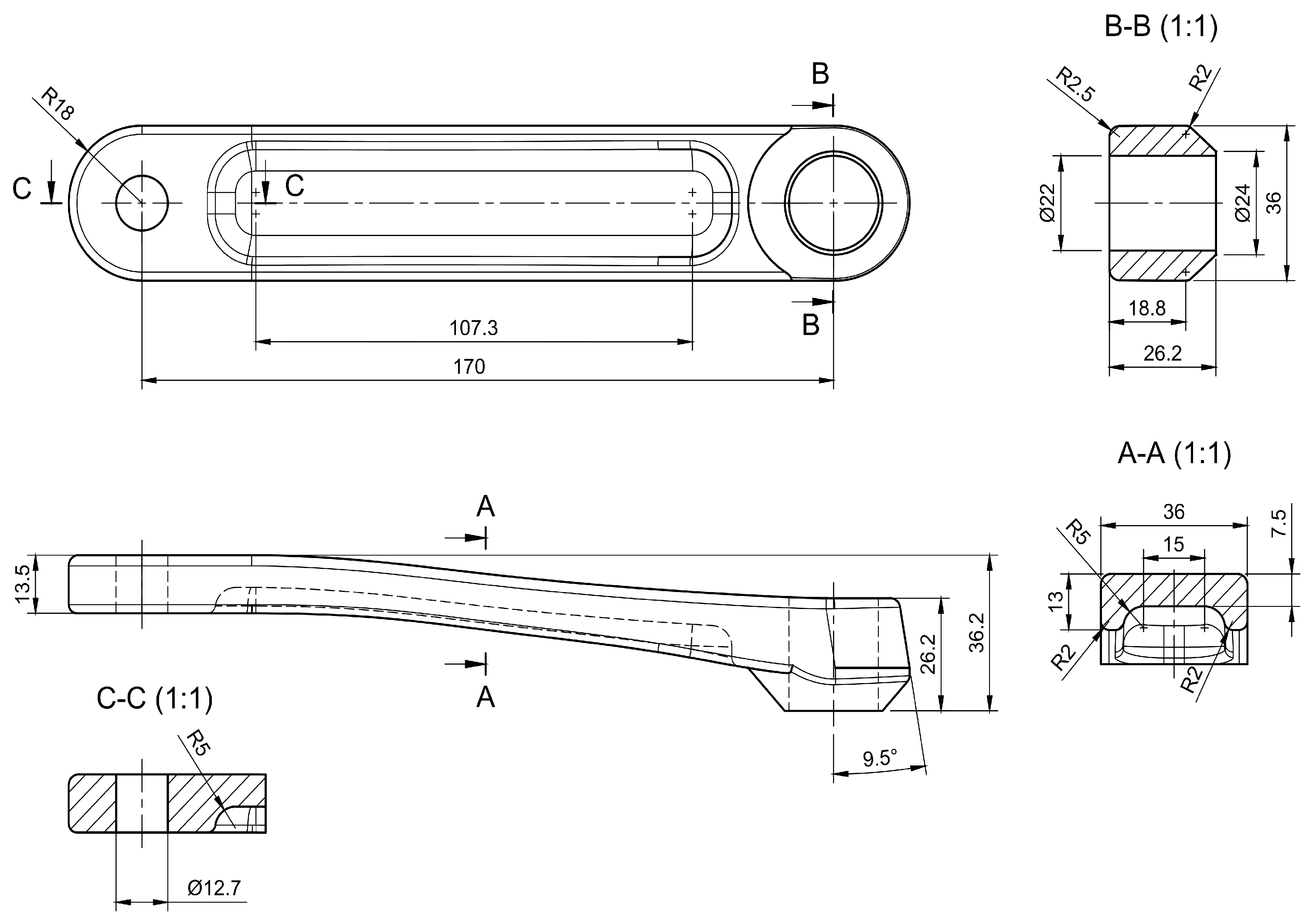
1.6. Crank Arm Design and Analysis
2. Materials and Methods
2.1. Analysis Method
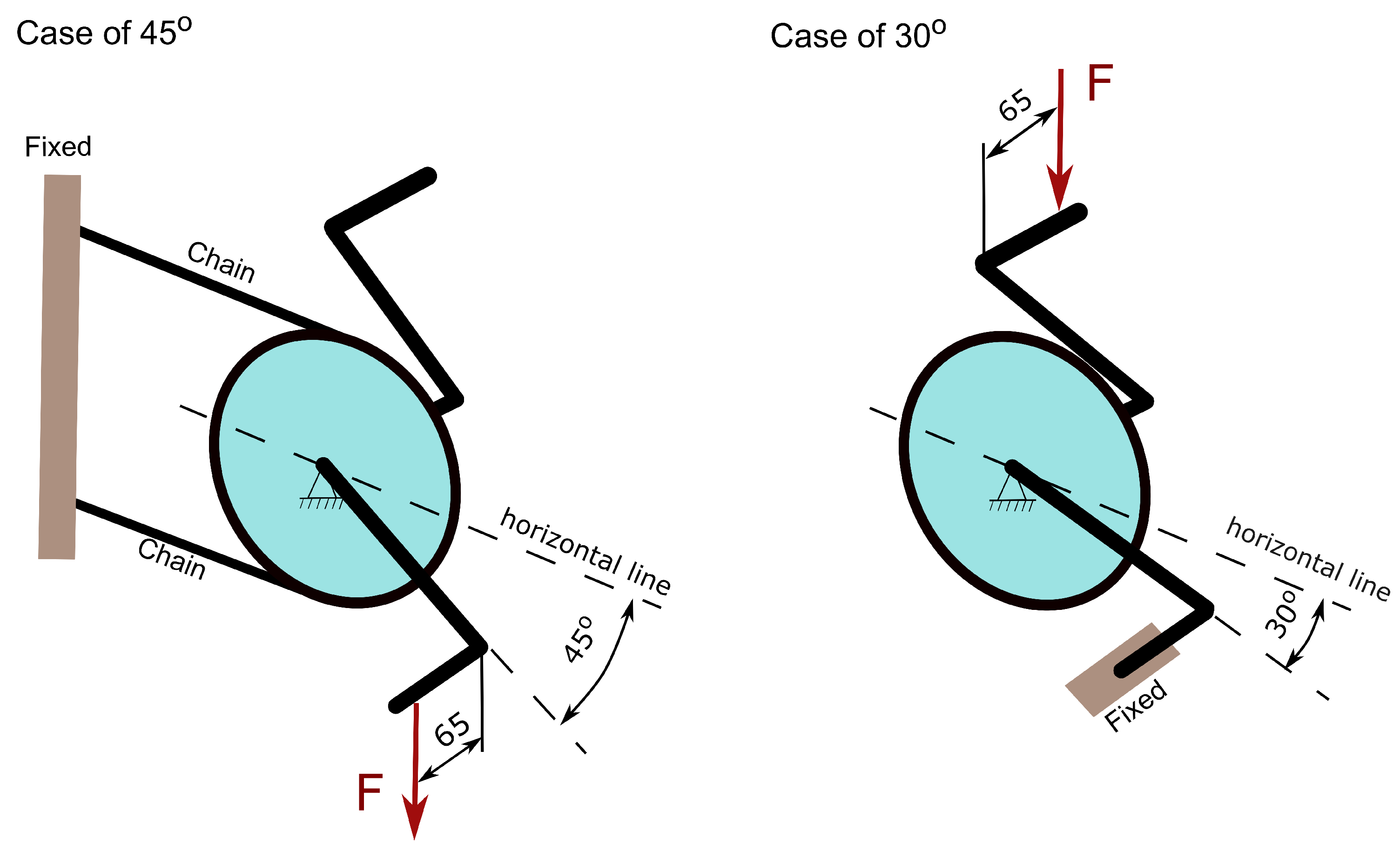
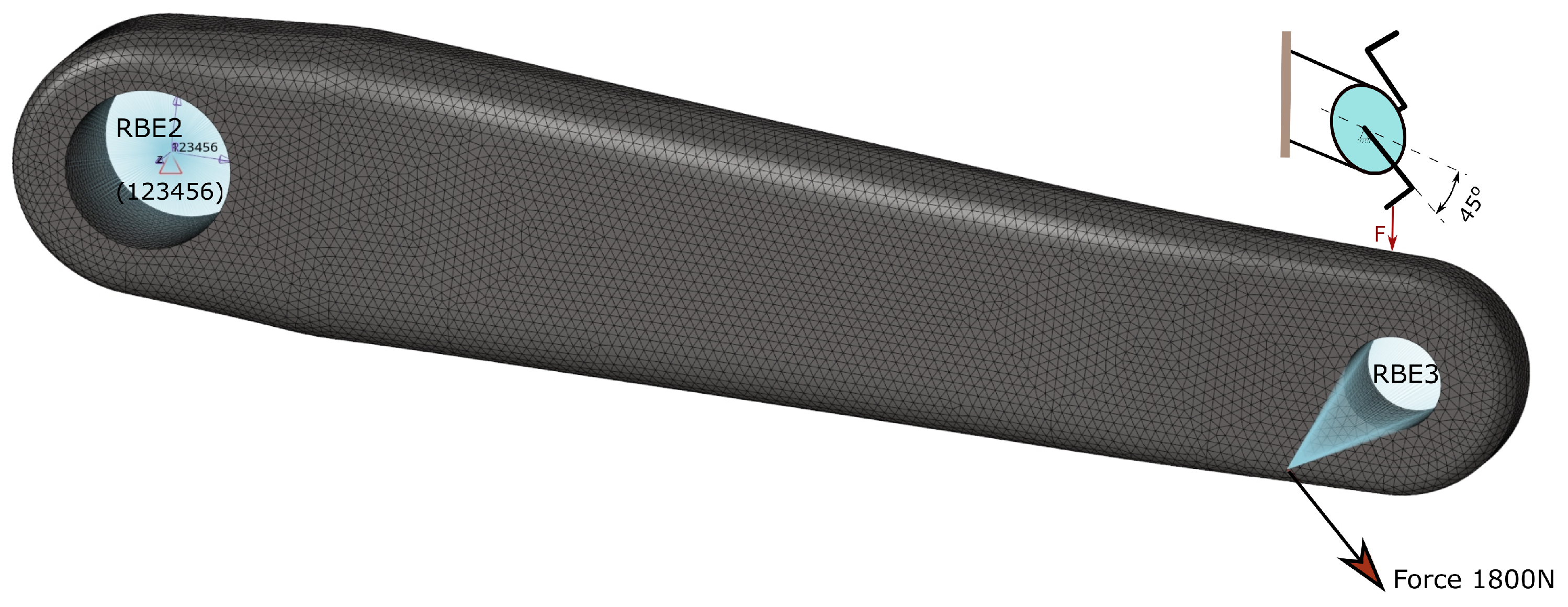
2.2. Loading and Assessment Criteria
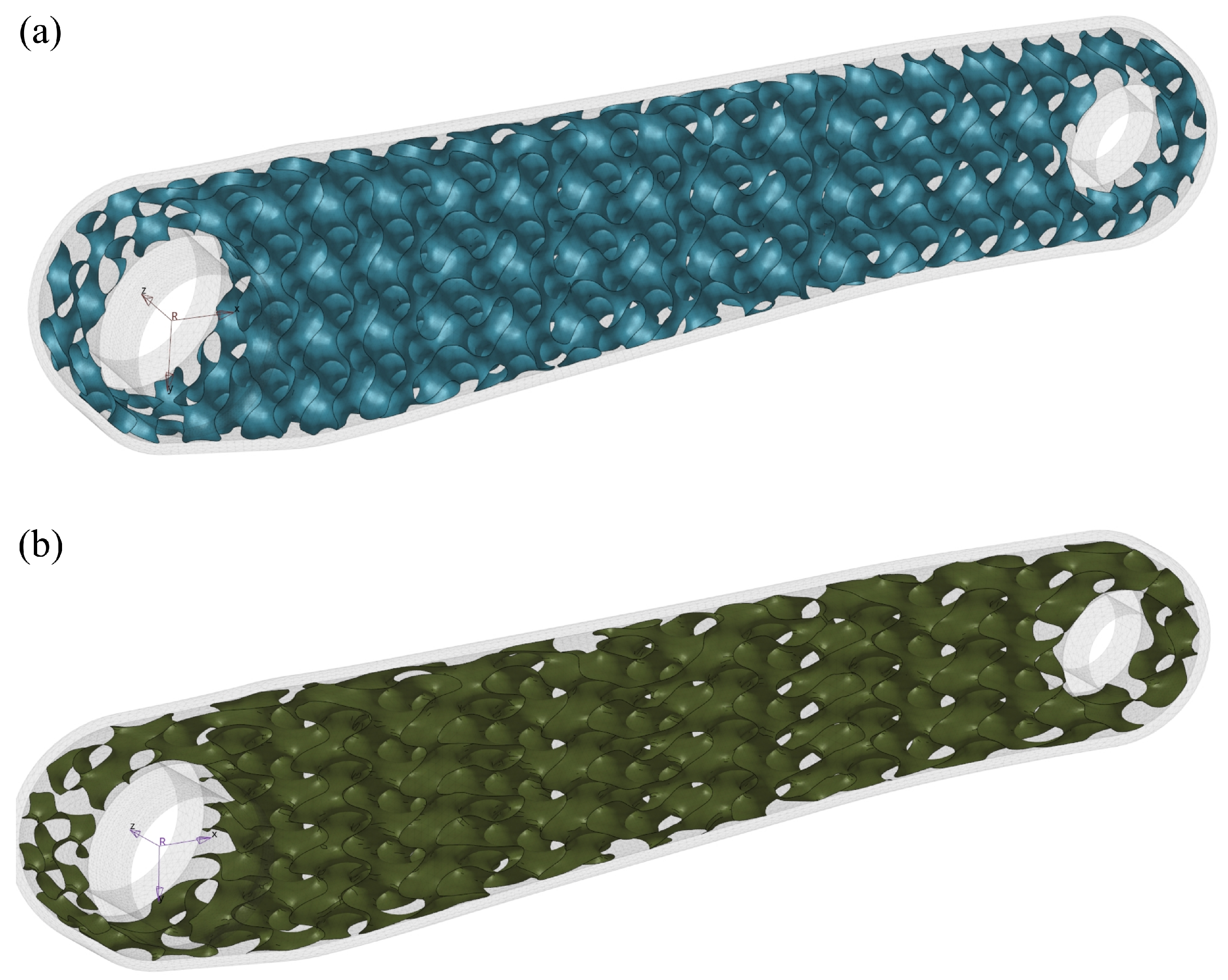
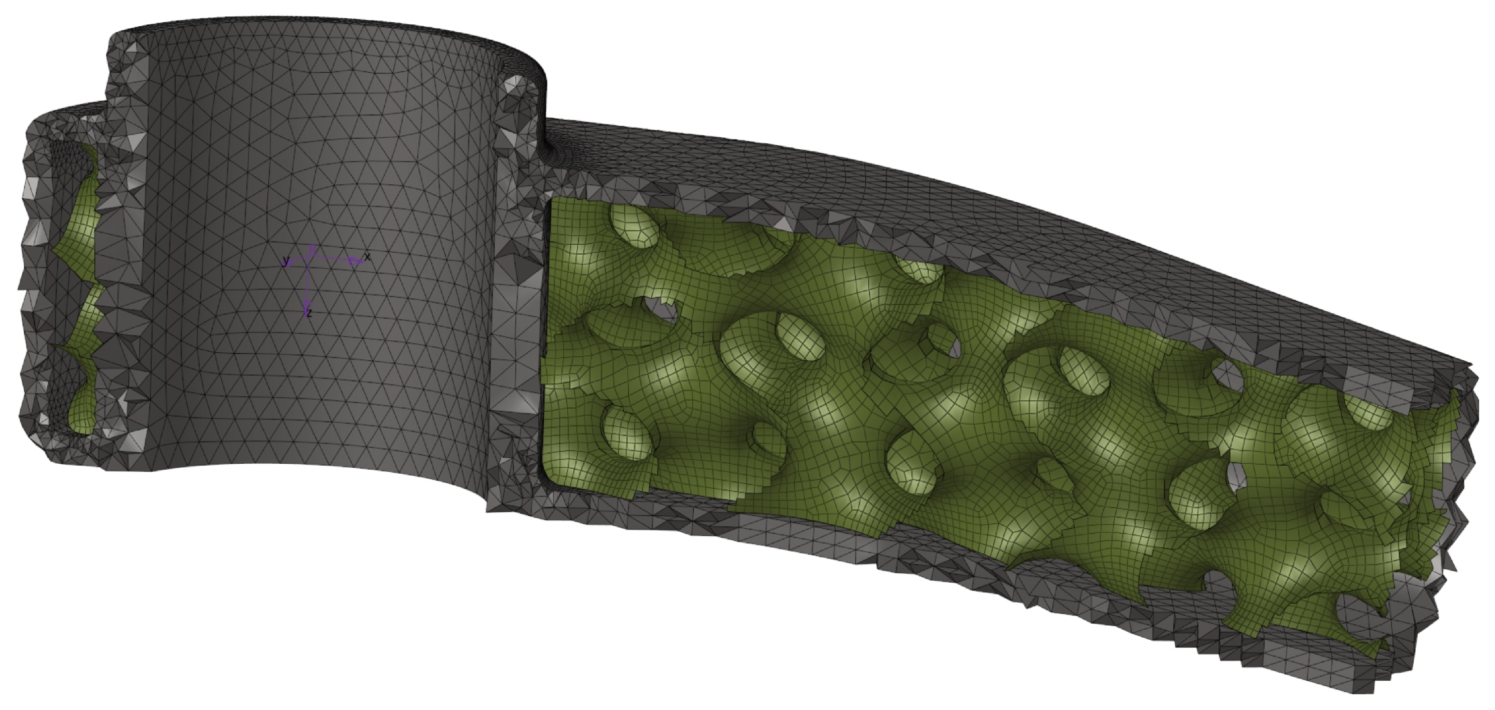
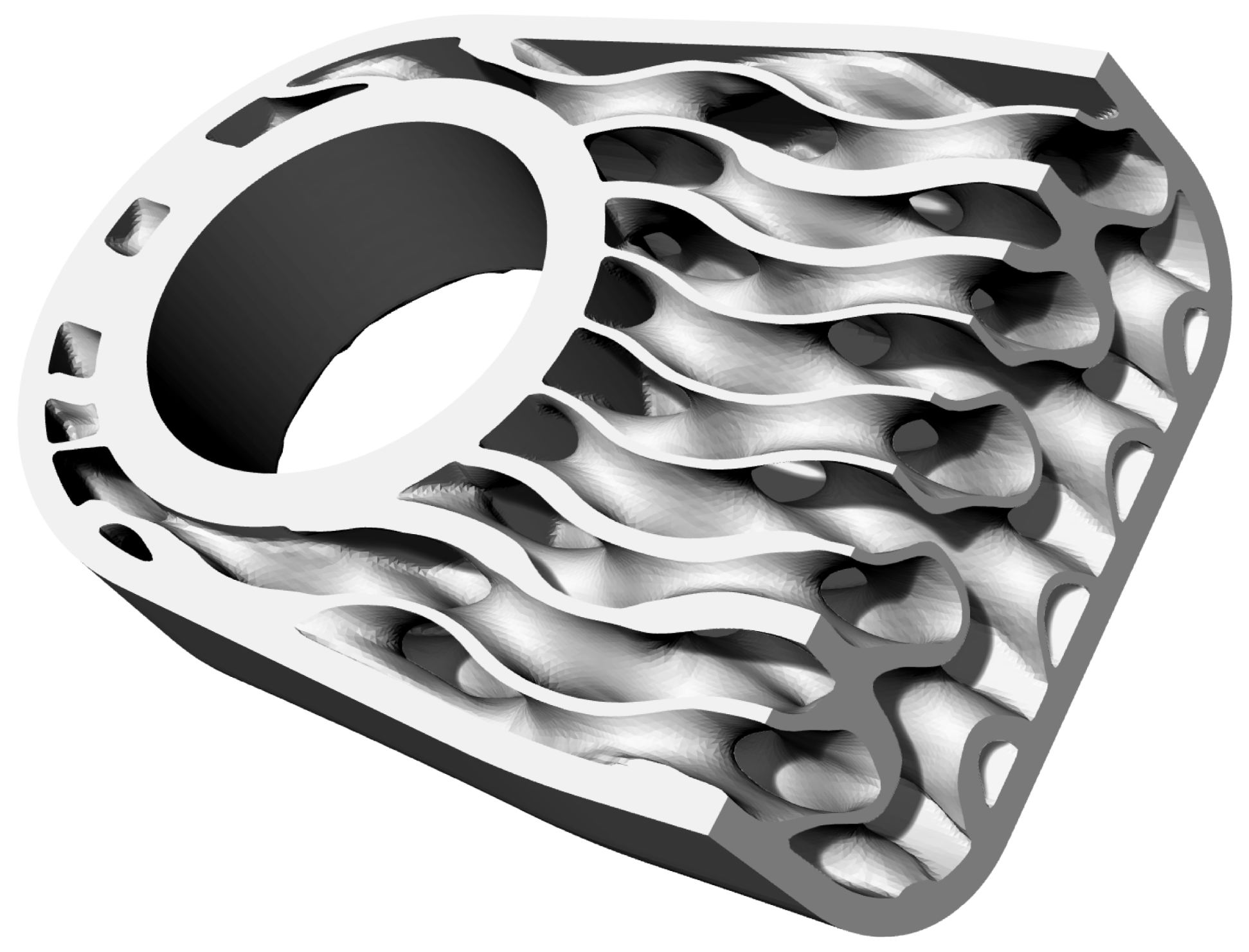
2.3. Infill as Surface-Lattice Structures
2.4. Manufacturing Constraints
- The material strength of the green parts determines the required support structure and limits the possible types of internal shell lattice structures.
- The sintering process limits the size of the printed parts and forces to use of support structures.
- The printed material and nozzle size determine the minimum thickness of a printed object.
- Metal X technology offers only some materials to print: 17–4 PH stainless steel, H13 tool steel, A2 tool steel, D2 tool steel, Inconel 625, and copper, whereas 316L stainless steel, titanium Ti6Al4V and aluminium are not yet available for this system.
- A substantial shrinkage after sintering reached approximately 20%, varying in a small range depending on part sizes.
- The material is characterised by high porosity because of the specific production process.
- Materials show strength anisotropy determined by a part orientation during printing.
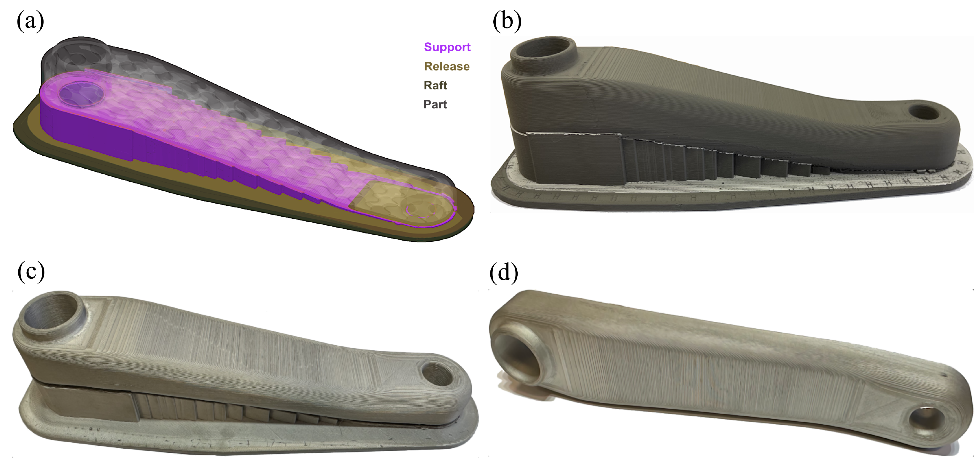
2.5. 3D Printing, Debinding and Sintering Parameters
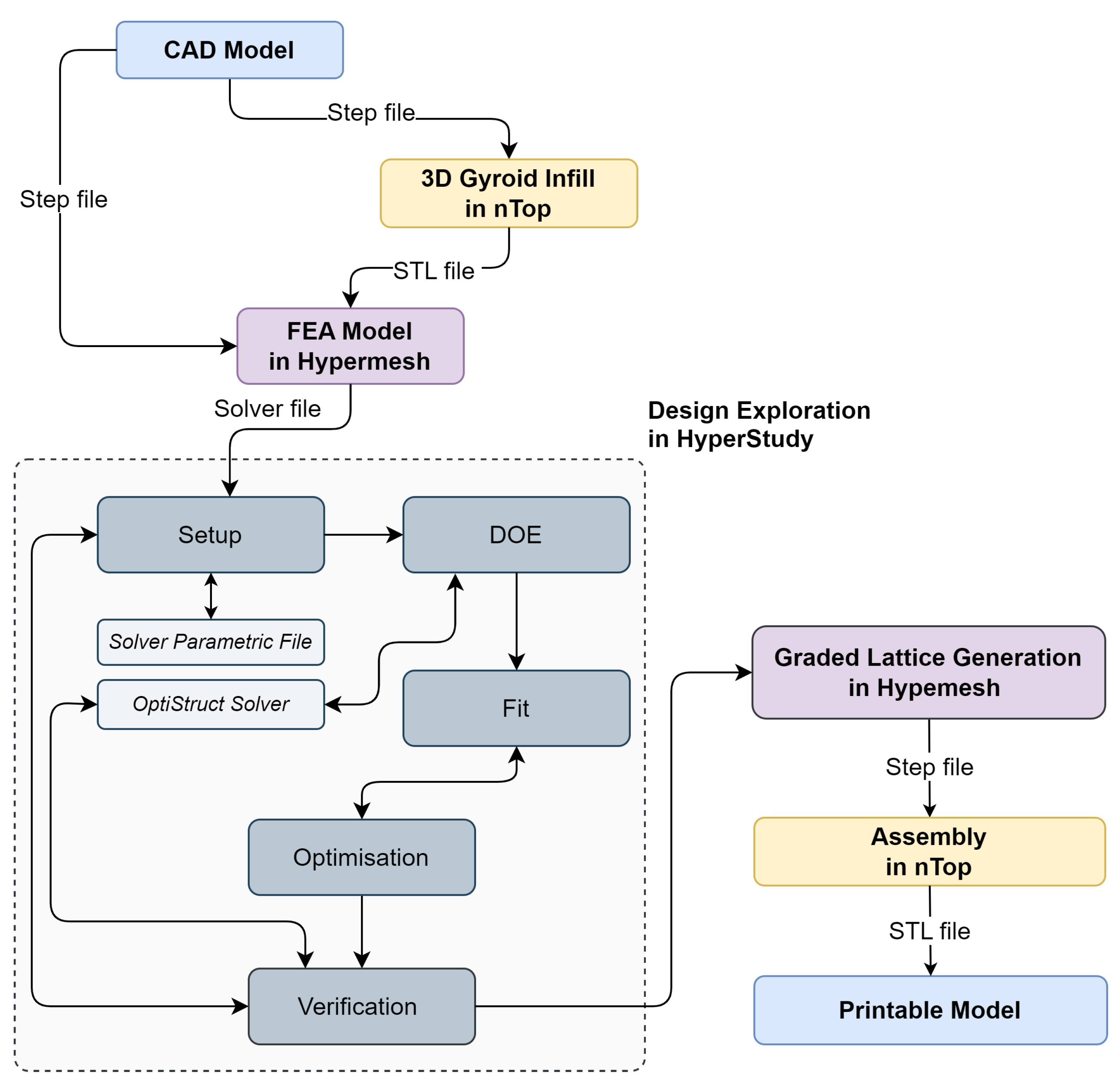
2.6. Design Exploration
2.7. Finite Element Model
2.7.1. Load and Boundary Conditions
2.7.2. Contact
2.7.3. Materials of Models
3. Results
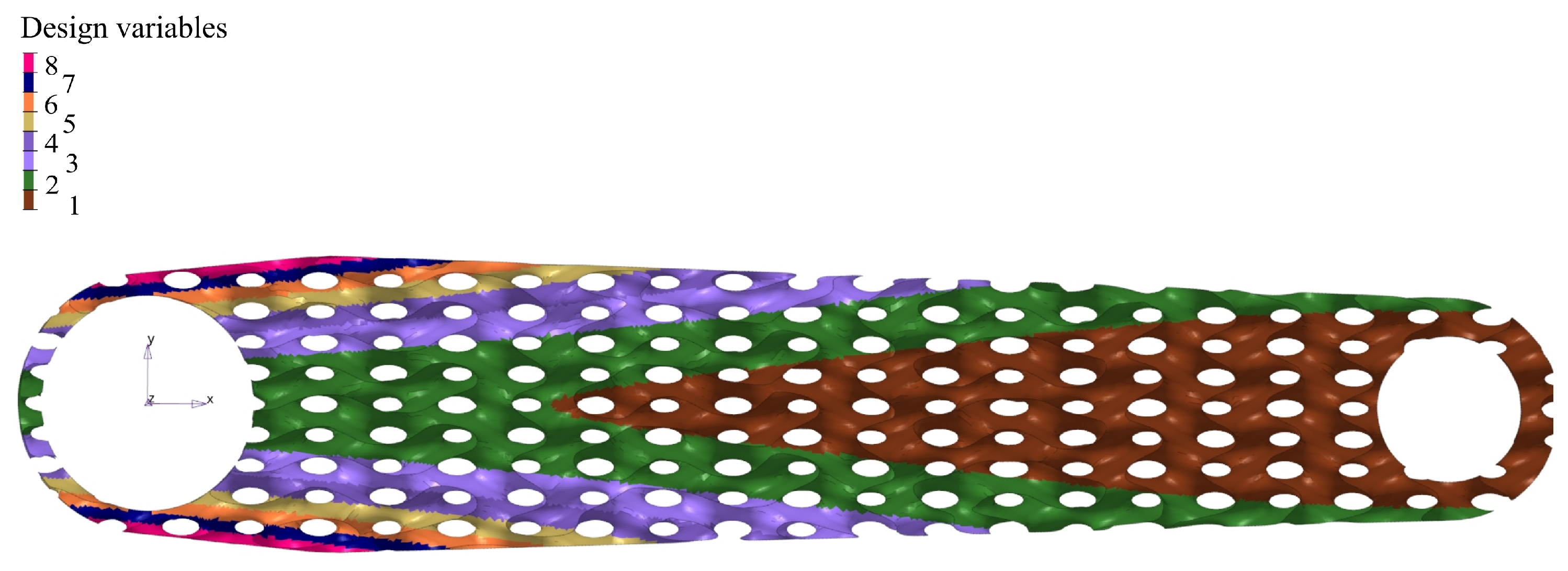
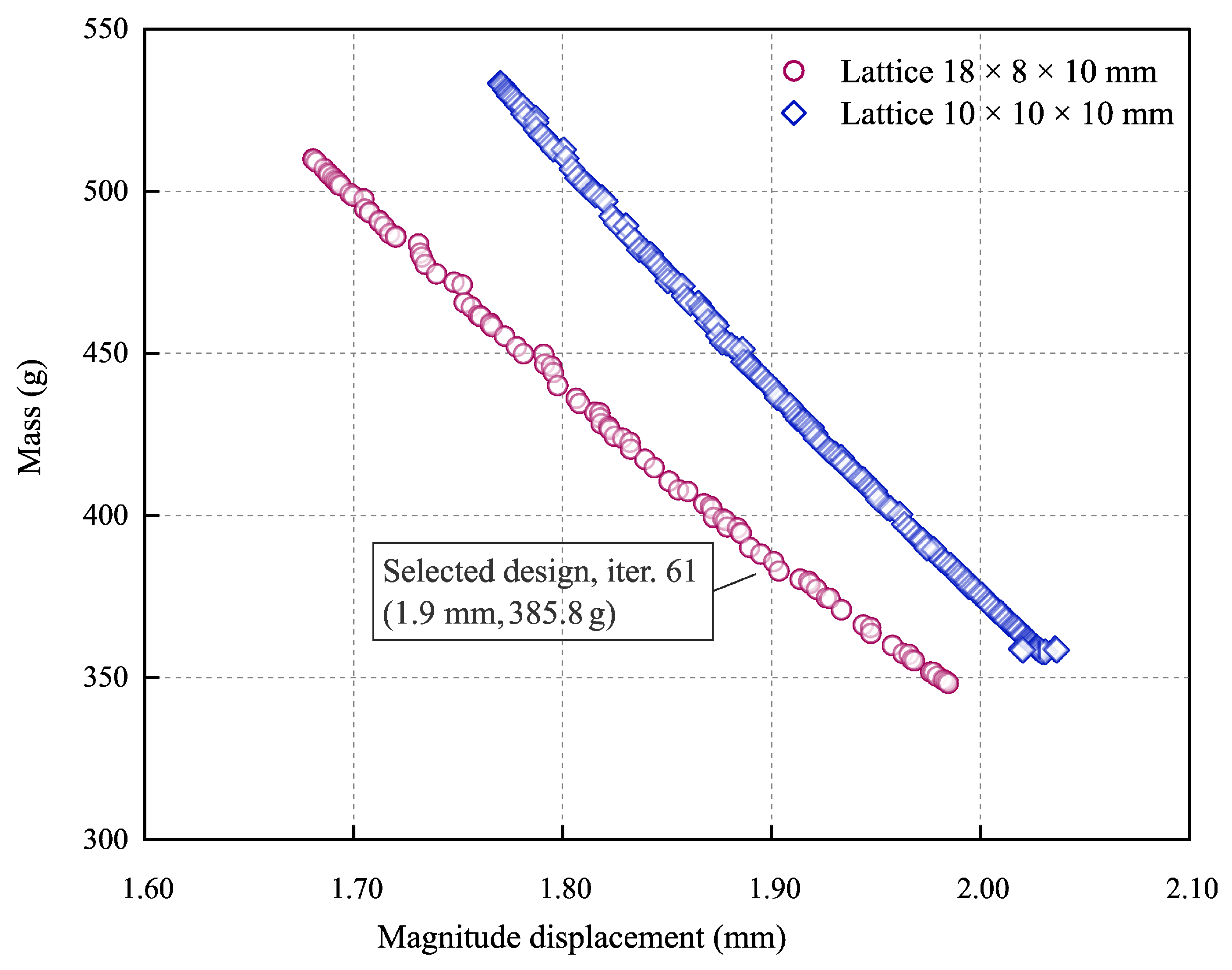
3.1. Design Exploration
3.2. Optimum Solution
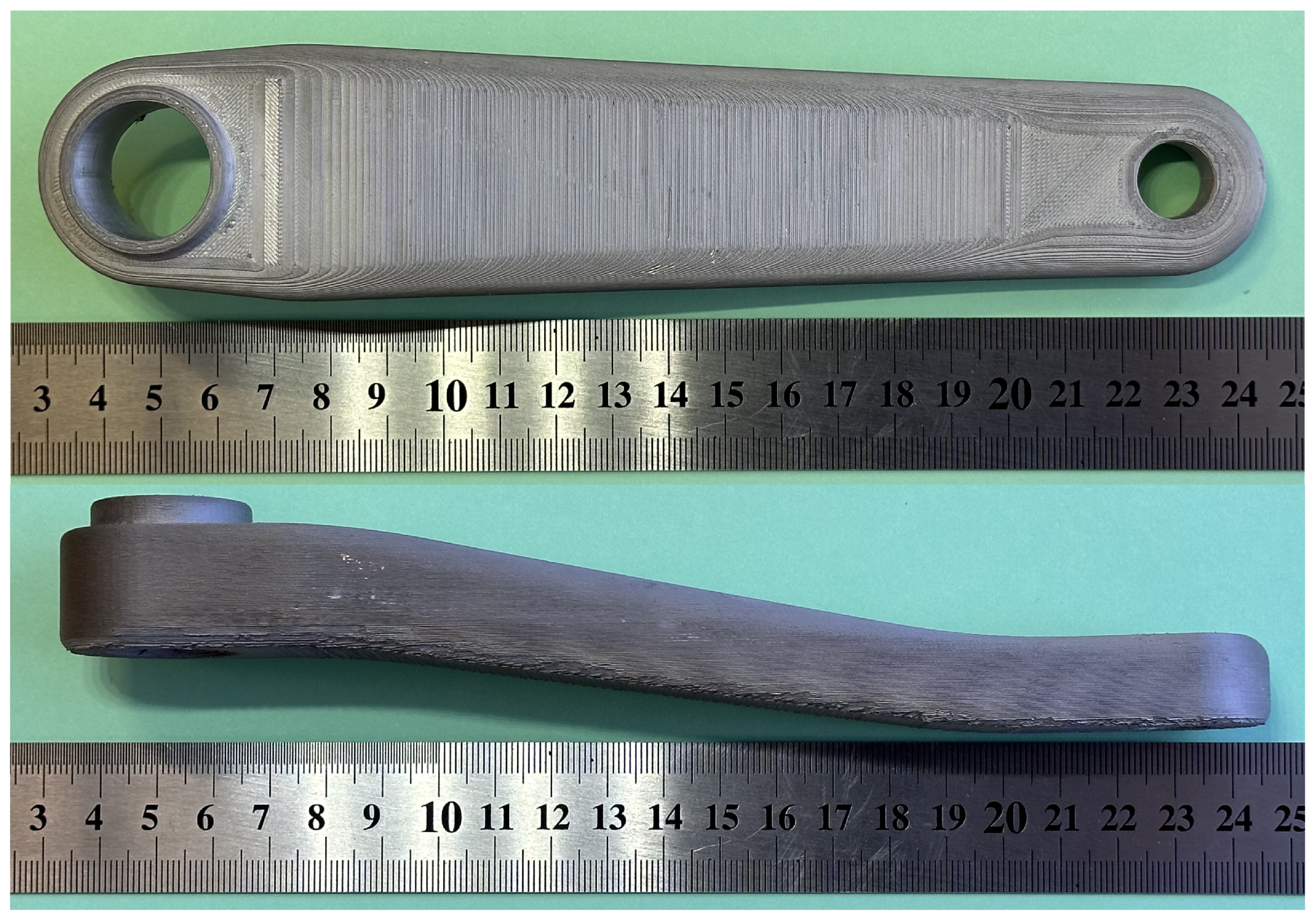
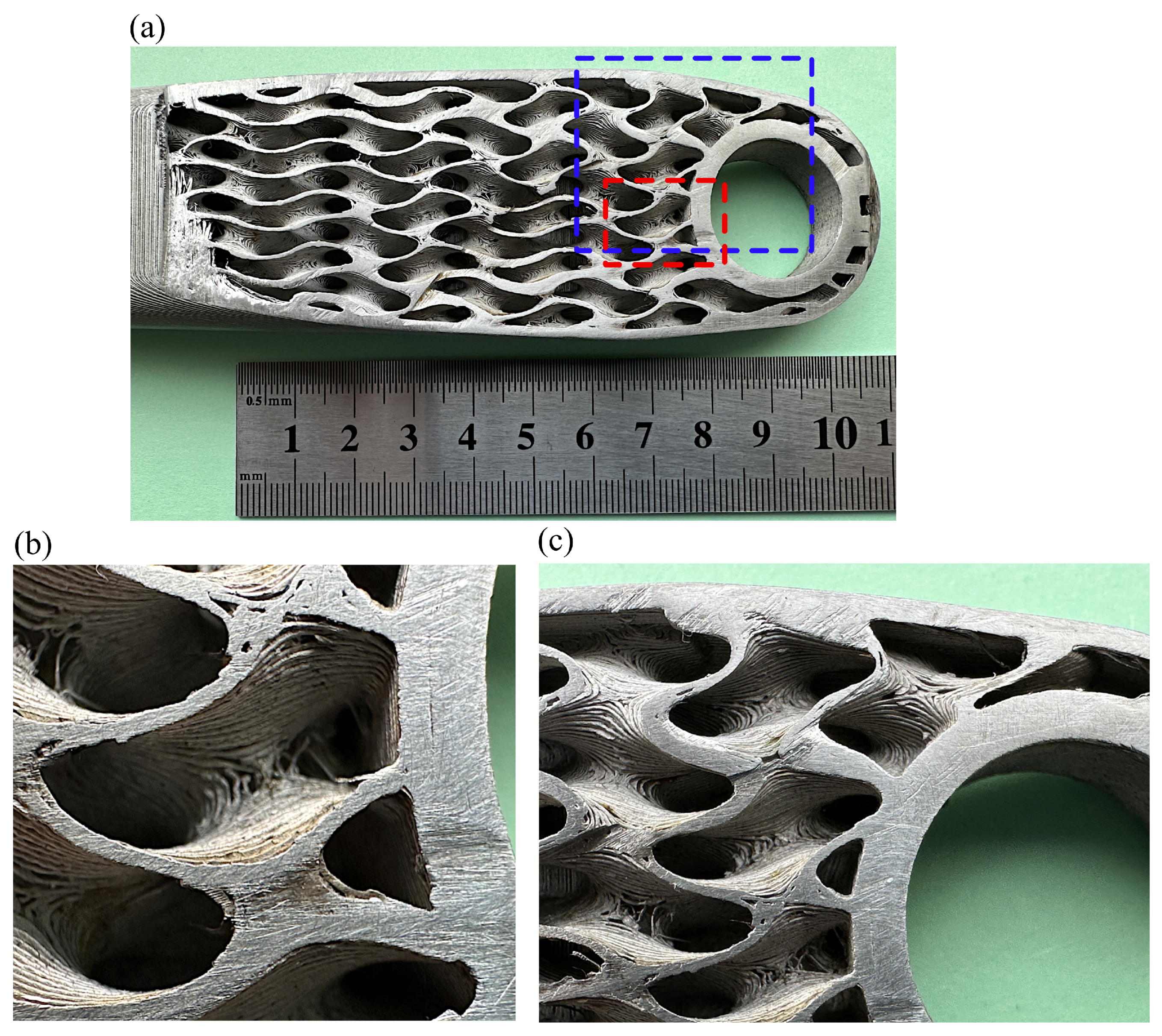
3.3. Prototype
4. Discussion
5. Conclusions
- Firstly, work is required to improve the metal FFF technology for printing thin-walled internal structures, with issues relating to nozzle size, printing parameters and printer control algorithms.
- Secondly, improvements are required in metallic filament materials for the metal FFF technology to enhance printability and reduction of post-sintered internal defects, thereby increasing the strength.
- Thirdly, it is recommended to develop methods for generating field-controlled lattice structures and integration in CAD systems that enhance design optimisation and exploration, opening up space for new types of high-performance parts.
Author Contributions
Funding
Institutional Review Board Statement
Informed Consent Statement
Data Availability Statement
Conflicts of Interest
Abbreviations
| AM | Additive Manufacturing |
| CAD | Computer-Aided Design |
| DE | Design Exploration |
| DOE | Design of Experiments |
| DSE | Design Space Exploration |
| FCC | Face-Centred Cubic |
| FDM | Fused Deposition Modelling |
| FEA | Finite Element Analysis |
| FFF | Fused Filament Fabrication |
| FGM | Functionally Graded Materials |
| FGS | Functionally Graded Structures |
| GRSM | Global Response Search Method |
| ISO | International Organisation for Standardisation |
| MELS | Modified Extensible Lattice Sequences |
| MEX | Metal Extrusion Method |
| MOO | Multiobjective Optimisation |
| nTop | nTopology |
| PBF | Powder Bed Fusion |
| SLS | Selective Laser Sintering |
| TPMS | Triply Periodic Minimal Surface |
References
- Munsch, M.; Schmidt-Lehr, M.; Wycisk, E. Binder Jetting and FDM: A Comparison with Laser Powder Bed Fusion and Metal Injection Moulding. Available online: https://www.metal-am.com/articles/binder-jetting-fdm-comparison-with-powder-bed-fusion-3d-printing-injection-moulding/ (accessed on 15 October 2022).
- Podroužek, J.; Marcon, M.; Ninčević, K.; Wan-Wendner, R. Bio-inspired 3D infill patterns for additive manufacturing and structural applications. Materials 2019, 12, 499. [Google Scholar] [CrossRef]
- Abate, K.M.; Nazir, A.; Yeh, Y.P.; Chen, J.E.; Jeng, J.Y. Design, optimization, and validation of mechanical properties of different cellular structures for biomedical application. Int. J. Adv. Manuf. Technol. 2020, 106, 1253–1265. [Google Scholar] [CrossRef]
- Afshar, M.; Anaraki, A.P.; Montazerian, H.; Kadkhodapour, J. Additive manufacturing and mechanical characterization of graded porosity scaffolds designed based on triply periodic minimal surface architectures. J. Mech. Behav. Biomed. Mater. 2016, 62, 481–494. [Google Scholar] [CrossRef]
- Jia, H.; Lei, H.; Wang, P.; Meng, J.; Li, C.; Zhou, H.; Zhang, X.; Fang, D. An experimental and numerical investigation of compressive response of designed Schwarz primitive triply periodic minimal surface with non-uniform shell thickness. Extrem. Mech. Lett. 2020, 37, 100671. [Google Scholar] [CrossRef]
- Lee, D.W.; Khan, K.A.; Abu Al-Rub, R.K. Stiffness and yield strength of architectured foams based on the Schwarz primitive triply periodic minimal surface. Int. J. Plast. 2017, 95, 1–20. [Google Scholar] [CrossRef]
- Li, Y.; Feng, Z.; Hao, L.; Huang, L.; Xin, C.; Wang, Y.; Bilotti, E.; Essa, K.; Zhang, H.; Li, Z.; et al. A review on functionally graded materials and structures via additive manufacturing: From multi-scale design to versatile functional properties. Adv. Mater. Technol. 2020, 5, 1900981. [Google Scholar] [CrossRef]
- Maskery, I.; Hussey, A.; Panesar, A.; Aremu, A.; Tuck, C.; Ashcroft, I.; Hague, R. An investigation into reinforced and functionally graded lattice structures. J. Cell. Plast. 2017, 53, 151–165. [Google Scholar] [CrossRef]
- Yang, L.; Yan, C.; Cao, W.; Liu, Z.; Song, B.; Wen, S.; Zhang, C.; Shi, Y.; Yang, S. Compression–compression fatigue behaviour of gyroid-type triply periodic minimal surface porous structures fabricated by selective laser melting. Acta Mater. 2019, 181, 49–66. [Google Scholar] [CrossRef]
- Aslan, B.; Yıldız, A.R. Optimum design of automobile components using lattice structures for additive manufacturing. Mater. Test. 2020, 62, 633–639. [Google Scholar] [CrossRef]
- Czerwinski, F. Current trends in automotive lightweighting strategies and materials. Materials 2021, 14, 6631. [Google Scholar] [CrossRef]
- Oczoś, K.E. Konstrukcje lekkie–istota, rodzaje, realizacja i zastosowanie. Cz. 1. Mechanik 2011, 84, 271–272. [Google Scholar]
- Oczoś, K.E. Konstrukcje lekkie–istota, rodzaje, realizacja i zastosowanie. Cz. 2. Mechanik 2011, 84, 377–390. [Google Scholar]
- Oftadeh, R.; Perez-Viloria, M.; Villa-Camacho, J.C.; Vaziri, A.; Nazarian, A. Biomechanics and mechanobiology of trabecular bone: A review. J. Biomech. Eng. 2015, 137, 010802. [Google Scholar] [CrossRef] [PubMed]
- Sato, M.; Inoue, A.; Shima, H. Bamboo-inspired optimal design for functionally graded hollow cylinders. PLoS ONE 2017, 12, e0175029. [Google Scholar] [CrossRef]
- Spencer, O.O.; Yusuf, O.T.; Tofade, T.C. Additive manufacturing technology development: A trajectory towards industrial revolution. Am. J. Mech. Ind. Eng. 2018, 3, 80–90. [Google Scholar] [CrossRef]
- Kedziora, S.; Decker, T.; Museyibov, E.; Morbach, J.; Hohmann, S.; Huwer, A.; Wahl, M. Strength properties of 316L and 17–4 PH stainless steel produced with additive manufacturing. Materials 2022, 15, 6278. [Google Scholar] [CrossRef]
- Koizumi, M. FGM activities in Japan. Compos. Part B Eng. 1997, 28, 1–4. [Google Scholar] [CrossRef]
- Saleh, B.; Jiang, J.; Fathi, R.; Al-hababi, T.; Xu, Q.; Wang, L.; Song, D.; Ma, A. 30 years of functionally graded materials: An overview of manufacturing methods, applications and future challenges. Compos. Part B Eng. 2020, 201, 108376. [Google Scholar] [CrossRef]
- Mahmoud, D.; Elbestawi, M. Lattice structures and functionally graded materials applications in additive manufacturing of orthopedic implants: A review. J. Manuf. Mater. Process. 2017, 1, 13. [Google Scholar] [CrossRef]
- Kou, X.Y.; Parks, G.T.; Tan, S.T. Optimal design of functionally graded materials using a procedural model and particle swarm optimization. CAD Comput. Aided Des. 2012, 44, 300–310. [Google Scholar] [CrossRef]
- Miyamato, Y.; Kaysser, W.A.; Rabin, B.H.; Kawasaki, A.; Ford, R.G. Functionally Graded Materials: Design, Processing and Application; Springer Science and Business Media: New York, NY, USA, 2013; Volume 1, pp. 1–339. [Google Scholar] [CrossRef]
- Wu, J.; Aage, N.; Westermann, R.; Sigmund, O. Infill optimization for additive manufacturing-approaching bone-like porous structures. IEEE Trans. Vis. Comput. Graph. 2018, 24, 1127–1140. [Google Scholar] [CrossRef] [PubMed]
- Gries, M. Methods for evaluating and covering the design space during early design development. Integr. VLSI J. 2004, 38, 131–183. [Google Scholar] [CrossRef]
- Kang, E.; Jackson, E.; Schulte, W. An approach for effective design space exploration. In Foundations of Computer Software. Modeling, Development, and Verification of Adaptive Systems; Springer: Berlin/Heidelberg, Germany, 2011. [Google Scholar] [CrossRef]
- Pan, C.; Han, Y.; Lu, J. Design and optimization of lattice structures: A review. Appl. Sci. 2020, 10, 6374. [Google Scholar] [CrossRef]
- Al-Saedi, D.S.J.; Masood, S.H.; Faizan-Ur-Rab, M.; Alomarah, A.; Ponnusamy, P. Mechanical properties and energy absorption capability of functionally graded F2BCC lattice fabricated by SLM. Mater. Des. 2018, 144, 32–44. [Google Scholar] [CrossRef]
- Zheng, X.; Lee, H.; Weisgraber, T.H.; Shusteff, M.; DeOtte, J.; Duoss, E.B.; Kuntz, J.D.; Biener, M.M.; Ge, Q.; Jackson, J.A.; et al. Ultralight, ultrastiff mechanical metamaterials. Science 2014, 344, 1373–1377. [Google Scholar] [CrossRef]
- Ashby, M.F. The properties of foams and lattices. Philos. Trans. R. Soc. A Math. Phys. Eng. Sci. 2006, 364, 15–30. [Google Scholar] [CrossRef]
- Deshpande, V.S.; Fleck, N.A.; Ashby, M.F. Effective properties of the octet-truss lattice material. J. Mech. Phys. Solids 2001, 49, 1747–1769. [Google Scholar] [CrossRef]
- Decker, T.; Kedziora, S.; Wolf, C. Practical Implementation of Functionally Graded Lattice Structures in a Bicycle Crank Arm. 2020. Available online: http://hdl.handle.net/10993/46747 (accessed on 28 May 2022).
- Schoen, A.H. Infinite Periodic Minimal Surfaces without Self-Intersections; Report; NASA: Washington, DC, USA, 1970.
- Abueidda, D.W.; Elhebeary, M.; Shiang, C.S.; Pang, S.; Abu Al-Rub, R.K.; Jasiuk, I.M. Mechanical properties of 3D printed polymeric gyroid cellular structures: Experimental and finite element study. Mater. Des. 2019, 165, 107597. [Google Scholar] [CrossRef]
- Bean, P.; Lopez-Anido, R.A.; Vel, S. Numerical modeling and experimental investigation of effective elastic properties of the 3D printed gyroid infill. Appl. Sci. 2022, 12, 2180. [Google Scholar] [CrossRef]
- Silva, C.; Pais, A.I.; Caldas, G.; Gouveia, B.P.P.A.; Alves, J.L.; Belinha, J. Study on 3D printing of gyroid-based structures for superior structural behaviour. Prog. Addit. Manuf. 2021, 6, 689–703. [Google Scholar] [CrossRef]
- Al-Ketan, O.; Abu Al-Rub, R.K. MSLattice: A free software for generating uniform and graded lattices based on triply periodic minimal surfaces. Mater. Des. Process. Commun. 2020, 3, e205. [Google Scholar] [CrossRef]
- Zhang, X.Y.; Yan, X.C.; Fang, G.; Liu, M. Biomechanical influence of structural variation strategies on functionally graded scaffolds constructed with triply periodic minimal surface. Addit. Manuf. 2020, 32, 101015. [Google Scholar] [CrossRef]
- Han, C.; Li, Y.; Wang, Q.; Wen, S.; Wei, Q.; Yan, C.; Hao, L.; Liu, J.; Shi, Y. Continuous functionally graded porous titanium scaffolds manufactured by selective laser melting for bone implants. J. Mech. Behav. Biomed. Mater. 2018, 80, 119–127. [Google Scholar] [CrossRef]
- Quaresimin, M.; Meneghetti, G.; Verardo, F. Design and optimisation of an RTM composite bicycle crank. J. Reinf. Plast. Compos. 2001, 20, 129–146. [Google Scholar] [CrossRef]
- McEwen, I.; Cooper, D.E.; Warnett, J.; Kourra, N.; Williams, M.A.; Gibbons, G.J. Design and manufacture of a high-performance bicycle crank by additive manufacturing. Appl. Sci. 2018, 8, 1360. [Google Scholar] [CrossRef]
- Gutiérrez-Moizant, R.; Ramírez-Berasategui, M.; Calvo, J.A.; Álvarez Caldas, C. Validation and improvement of a bicycle crank arm based in numerical simulation and uncertainty quantification. Sensors 2020, 20, 1814. [Google Scholar] [CrossRef]
- Chang, R.R.; Dai, W.J.; Wu, F.Y.; Jia, S.Y.; Tan, H.M. Design and manufacturing of a laminated composite bicycle crank. Procedia Eng. 2013, 67, 497–505. [Google Scholar] [CrossRef]
- nTopology. nTopology, Version 3.45.4. Available online: https://ntopology.com/ntop-platform (accessed on 4 April 2023).
- ISO 4210-8:2023; Cycles—Safety Requirements for Bicycles—Part 8: Pedal and Drive System Test Methods. ISO: Geneva, Switzerland, 2023.
- Whitt, F.R.; Wilson, D.G. Bicycling Science, 2nd ed.; MIT Press: Cambridge, MA, USA, 1982; p. 364. [Google Scholar]
- Markforged, T. Metal-X System. Available online: https://markforged.com/metal-x/ (accessed on 15 March 2022).
- Basf, T. Ultrafuse FFF. Available online: https://www.ultrafusefff.com/product-category/metal/ultrafuse-316l/ (accessed on 14 February 2021).
- Foundry, T.V. Manufacturing Metal 3D Printing Filaments and Materials. Available online: https://www.thevirtualfoundry.com/ (accessed on 12 September 2022).
- Desktop Metal Inc. Studio System™ 2. Available online: https://www.desktopmetal.com/products/studio (accessed on 12 May 2022).
- Altair Engineering Inc. HyperStudy Guide, 2022.1. Available online: https://altairhyperworks.com/product/HyperStudy (accessed on 3 February 2023).
- Altair Engineering Inc. OptiStruct, Version 2022.1. Available online: https://www.altair.com/optistruct/ (accessed on 8 February 2023).
- Jaimes, A.L.; Martínez, S.Z.; Coello, C.A.C. An introduction to multiobjective optimization techniques. In Optimization in Polymer Processing; Chemical Engineering Methods and Technology; Nova Science Publishers: Hauppauge, NY, USA, 2011; pp. 29–57. [Google Scholar]
- Engineering, A. Altair HyperStudy Guide, Version 2022.1, DOE Modified Extensible Lattice Sequence. Available online: https://2022.help.altair.com/2022.1/hwdesktop/hst/topics/design_exploration/method_modified_extensible_lattice_sequence_doe_r.htm (accessed on 3 April 2023).
- Ollar, J. A Multidisciplinary Design Optimisation Framework for Structural Problems with Disparate Variable Dependence. Ph.D. Thesis, Queen Mary University of London, London, UK, 2016. [Google Scholar]
- Markforged, T. 17–4 PH Stainless Steel. Available online: https://static.markforged.com/downloads/17-4-ph-stainless-steel.pdf (accessed on 9 November 2022).
- Bjørheim, F.; Lopez, I.L.T. Tension testing of additively manufactured specimens of 17–4 PH processed by bound metal deposition. IOP Conf. Ser. Mater. Sci. Eng. 2021, 1201, 012037. [Google Scholar] [CrossRef]
- Morgan, J.E.; Wagg, D.J. The failure of bike cranks, International Standards, tests and interpretations. Sport. Eng. 2002, 5, 113–119. [Google Scholar] [CrossRef]
- Engineering, M. Component Failure Museum, Bicycle Crank Failure II. Available online: http://technology.open.ac.uk/materials/mem/mem_ccf4.htm (accessed on 15 July 2022).
- Markforged, T. Eiger.io, Slicer 3.97.0. Available online: https://www.eiger.io/ (accessed on 9 January 2023).
- Günaydın, A.C.; Yıldız, A.R.; Kaya, N. Multi-objective optimization of build orientation considering support structure volume and build time in laser powder bed fusion. Mater. Test. 2022, 64, 323–338. [Google Scholar] [CrossRef]


| Printing Parameters | Value |
|---|---|
| Nozzle size, mm | 0.4 |
| Layer height, mm | 0.125 |
| Print bed temperature, °C | 115 |
| Metal hotend temperature, °C | 220 |
| Chamber temperature, °C | 48 |
| Oversizing factors: X, Y, Z, % | 19.5, 19.5, 20 |
| Parameters | [16] | [54] | [55] |
|---|---|---|---|
| Print direction | ZX (Upright) | XY (Flat) | XZ (On Edge) |
| Young’s modulus, GPa | 142 | 140 | 189 |
| Poisson’ ratio | - | 0.272 | - |
| Tensile strength, MPa | 496 | 1050 | 815 |
| Yield strength, MPa | 441 | 800 | 650 |
| Elongation at break, % | 0.4 | 5 | 0.86 |
| Density, g/cm3 | - | 7.44 | - |
| Hardness | 261 HB | 30 HRC | - |
| Parameters | Stainless Steel 17–4 PH (As-Sintered) | Aluminium 6061–T6 |
|---|---|---|
| Young’s modulus, GPa | 170 | 69 |
| Poisson’ ratio | 0.27 | 0.33 |
| Stress limit, MPa | 360 | - |
| Density, g/cm3 | 7.44 | 2.7 |
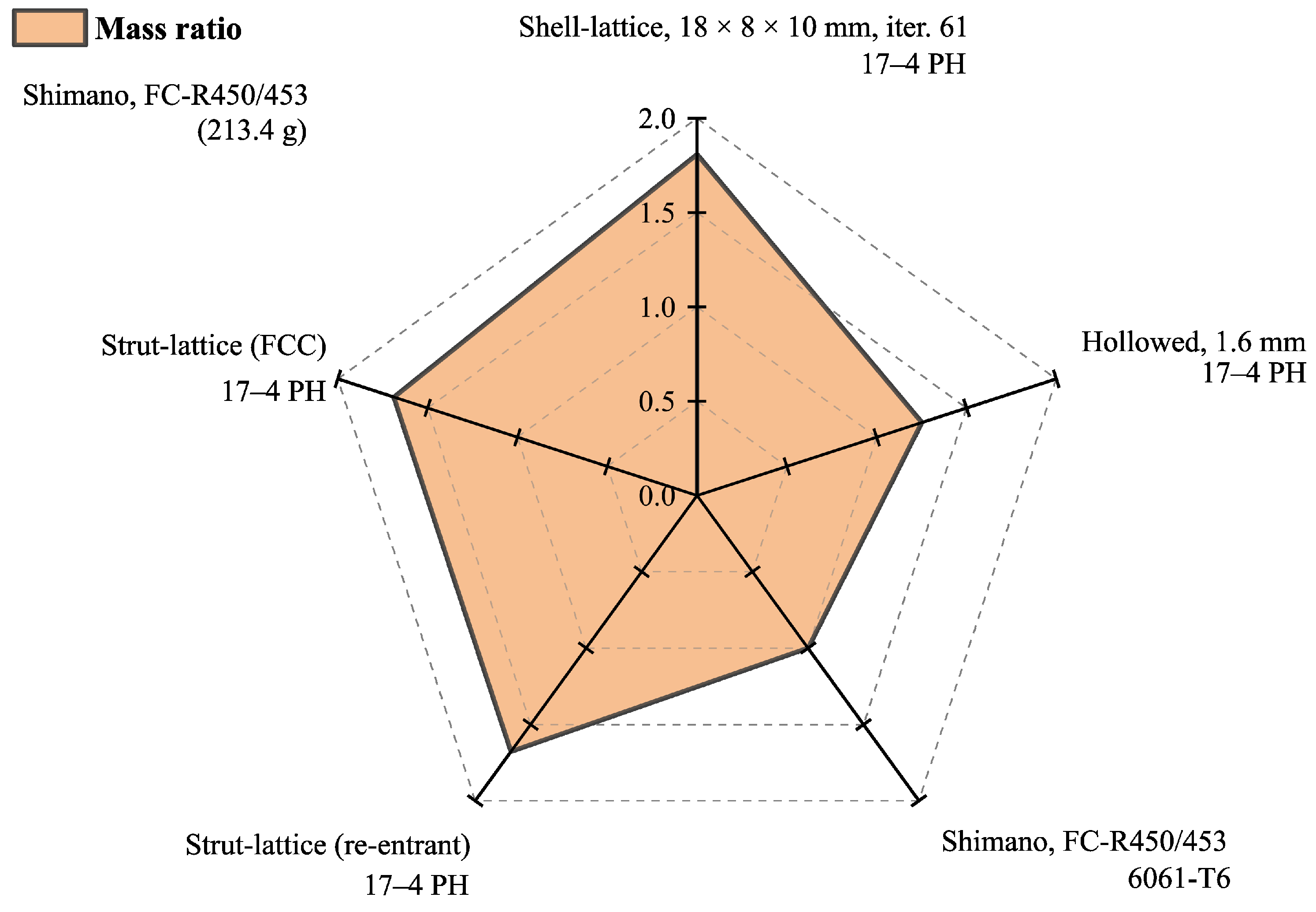
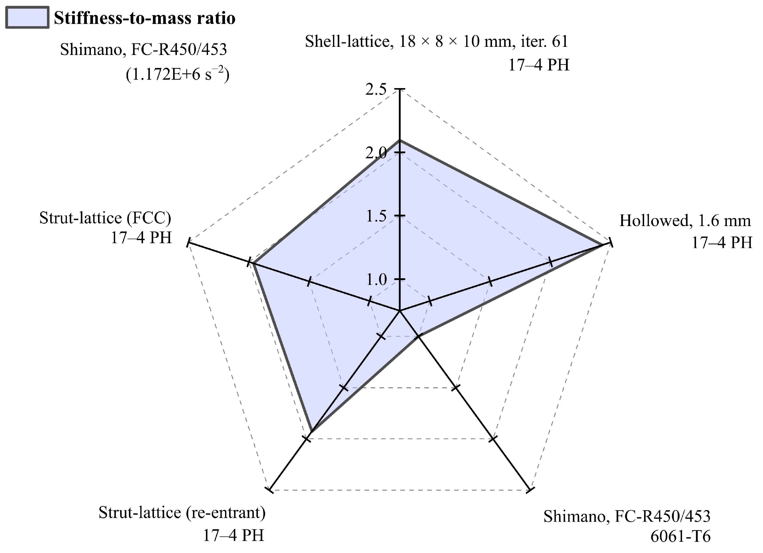
| Design | Material | Mass, g | Displacement, mm | Stiffness, N/mm | Stiffness-to-Mass, |
|---|---|---|---|---|---|
| Shimano FC-R450/453 | 6061–T6 | 213.4 | 7.20 | 250.2 | 1.172 |
| Strut-lattice (re-entrant) | 17–4 PH | 357.0 | 2.61 | 689.7 | 1.927 |
| Strut-lattice (FCC) | 17–4 PH | 360.0 | 2.55 | 705.9 | 1.961 |
| 18 × 8 × 10 mm (Iter. 61) | 17–4 PH | 385.8 * | 1.90 | 947.4 | 2.456 |
| Hollowed, 1.6 mm | 17–4 PH | 267.3 | 2.37 | 760.5 | 2.845 |
Disclaimer/Publisher’s Note: The statements, opinions and data contained in all publications are solely those of the individual author(s) and contributor(s) and not of MDPI and/or the editor(s). MDPI and/or the editor(s) disclaim responsibility for any injury to people or property resulting from any ideas, methods, instructions or products referred to in the content. |
© 2023 by the authors. Licensee MDPI, Basel, Switzerland. This article is an open access article distributed under the terms and conditions of the Creative Commons Attribution (CC BY) license (https://creativecommons.org/licenses/by/4.0/).
Share and Cite
Kedziora, S.; Decker, T.; Museyibov, E. Application of Functionally Graded Shell Lattice as Infill in Additive Manufacturing. Materials 2023, 16, 4401. https://doi.org/10.3390/ma16124401
Kedziora S, Decker T, Museyibov E. Application of Functionally Graded Shell Lattice as Infill in Additive Manufacturing. Materials. 2023; 16(12):4401. https://doi.org/10.3390/ma16124401
Chicago/Turabian StyleKedziora, Slawomir, Thierry Decker, and Elvin Museyibov. 2023. "Application of Functionally Graded Shell Lattice as Infill in Additive Manufacturing" Materials 16, no. 12: 4401. https://doi.org/10.3390/ma16124401
APA StyleKedziora, S., Decker, T., & Museyibov, E. (2023). Application of Functionally Graded Shell Lattice as Infill in Additive Manufacturing. Materials, 16(12), 4401. https://doi.org/10.3390/ma16124401