Article

Preparation of Monolithic LaFeO3 and Catalytic Oxidation of Toluene

1
College of Materials Science and Engineering, Nanjing Tech University, Nanjing 211800, China
2
State Key Laboratory of Materials-Oriented Chemical Engineering, Nanjing 211800, China
*
Author to whom correspondence should be addressed.
Materials 2023, 16(11), 3948; https://doi.org/10.3390/ma16113948
Submission received: 27 April 2023 / Revised: 21 May 2023 / Accepted: 22 May 2023 / Published: 25 May 2023

Abstract

:
Porous LaFeO3 powders were produced by high-temperature calcination of LaFeO3 precursors obtained by hydrothermal treatment of corresponding nitrates in the presence of citric acid. Four LaFeO3 powders calcinated at different temperatures were mixed with appropriate amounts of kaolinite, carboxymethyl cellulose, glycerol and active carbon for the preparation of monolithic LaFeO3 by extrusion. Porous LaFeO3 powders were characterized using powder X-ray diffraction, scanning electron microscopy, nitrogen absorption/desorption and X-ray photoelectron spectroscopy. Among the four monolithic LaFeO3 catalysts, the catalyst calcinated at 700 °C showed the best catalytic activity for the catalytic oxidation of toluene at 36,000 mL/(g∙h), and the corresponding T10%, T50% and T90% was 76 °C, 253 °C and 420 °C, respectively. The catalytic performance is attributed to the larger specific surface area (23.41 m2/g), higher surface adsorption of oxygen concentration and larger Fe2+/Fe3+ ratio associated with LaFeO3 calcined at 700 °C.

1. Introduction

Volatile organic compounds, abbreviated as VOCs, are compounds with a low boiling point at ambient temperature and pressure [1]. VOCs are a large class of carbon-based compounds, most of which are diffusible, flammable, explosive or toxic. VOCs are considered to be the main sources of atmospheric pollution, posing serious ecological and human health hazards [2,3,4,5]. Such pollutants are produced either naturally or by human activities. Pollution due to human activities can be divided into two types: indoor and outdoor. Outdoor sources account for a large proportion of pollution from chemical plants, power plants, pharmaceutical plants, refineries and gas stations, as well as food processing, automobile manufacturing, furniture and textiles [6,7,8]. Volatile organic compounds are also harmful pollutants indoor air [9]. The main sources of indoor VOCs are solvents, glues, insulation materials, cooking and smoking waste [10,11,12]. When VOCs are emitted into the atmosphere, these high concentrations of VOCs can cause nausea, dizziness and headaches, some damage to human organs as well as the nervous system and even chronic or acute poisoning, leading to cancer in severe cases [13,14]. Decomposition of VOCs into non-toxic compounds is important for our environment.
Typical methods to deal with VOCs are condensation [15], adsorption [16], absorption [17], plasma technology [18], catalytic oxidation [19,20,21,22] and biodegradation [23]. Among these methods, catalytic oxidation technology converts volatile organic compounds directly into water and carbon dioxide without causing secondary pollution to the environment. The catalysts that have been used for environmental purposes are noble metal catalysts and metal oxide catalysts. Although noble metal catalysts show high catalytic activity for VOCs, their use is limited due to the high price and low availability [24]. Based on this situation, metal oxide catalysts are regarded as a good alternative to the noble metal catalyst due to their low price, ease of preparation, stability and good resistance to toxicity [25]. Perovskite oxides have been extensively studied in the catalytic oxidation of VOCs and have shown high catalytic activity during the oxidation process [26,27]. LaFeO3 is a typical perovskite that is widely used for catalytic oxidation [28,29,30,31] and gas and biosensors [32,33,34] due to its good catalytic activity and high stability. It is also used in solid oxide fuel cells [35] by virtue of its excellent catalytic activity, high electrical conductivity and oxygen mobility. To achieve a high catalytic performance, the LaFeO3 catalyst with a porous structure is desirable since porous materials possess a higher specific surface area. At the same time, monolithic catalysts have advantages over powder catalysts, such as better thermal conductivity and lower reactor pressure [36]. Therefore, the rational design of a monolithic catalyst with porous structure, high stability and good catalytic activity is of great significance.
In this study, powder LaFeO3 was synthesized by conventional high temperature calcination of LaFeO3 precursors, which were obtained using a simple hydrothermal route. Monolithic LaFeO3 catalysts were then prepared by mixing with kaolinite, carboxymethyl cellulose, glycerol and active carbon followed by a single extrusion method. Four monolithic LaFeO3 catalysts were prepared using LaFeO3 powders calcinated at 500 °C, 600 °C, 700 °C and 800 °C. The flow chart of powder LaFeO3 preparation is shown in Figure 1. The structure and physical and chemical properties of each catalyst were investigated using techniques including powder X-ray diffraction (XRD), scanning electron microscopy (SEM), X-ray photoelectron spectroscopy (XPS) and Brunauer–Emmett–Teller (BET) analysis. The monolithic 700 °C LaFeO3 catalyst with a large specific surface area, a high Fe2+/Fe3+ ratio and an abundant concentration of adsorbed oxygen exhibits excellent catalytic activity.

2. Materials and Methods

2.1. Materials

Ferric nitrate hydrate (Fe(NO3)3·9H2O) was purchased from Sinopharm Chemical Reagent Co. Lanthanum Nitrate Hexahydrate (La(NO3)3·6H2O) was supplied by Shanghai Aladdin Biochemical Technology Co. Citric acid monohydrate (C6H8O7·H2O) was purchased from Shanghai Lingfeng Chemical Reagent Co. Sodium Carboxymethyl cellulose ([C6H7O2(OH)2OCH2COONa]n) was provided by Sinopharm Chemical Reagent Co. Glycerol (C3H8O3) was provided by Shanghai Lingfeng Chemical Reagent Co. Kaolin (Al2O3·2SiO2·2H2O) was bought from Henan Plutonium Casting Material Co. Carbon (C) powder was provided by Tianjin Lihua Jin Chemical Co. All chemical reagents are of analytical grade and used without further purification.

2.2. Synthesis of LaFeO3 Powders

The powder LaFeO3 perovskite catalyst was synthesized by a hydrothermal method. Next, 1.299 g La(NO3)3·6H2O, 2.424 g Fe(NO3)3·9H2O, and 3.78 g citric acid monohydrate were added to 60 mL of deionized water with a molar ratio of n(La):n(Fe):n(citric acid) = 1:1.5:6 molar ratio and stirred for 30 min to yield a clear solution. The solution was transferred to a 100 mL PTFE-lined stainless-steel autoclave and kept at 180 °C in an oven for 8 h. The resulting solid yellow product was filtered and washed several times with distilled water and anhydrous ethanol. The resulting yellow product was dried at 80 °C for several hours and ground followed by calcination at appropriate temperatures. The final product calcinated at 500 °C, 600 °C, 700 °C and 800 °C, is denoted as 500 LFO, 600 LFO, 700 LFO and 800 LFO, respectively. The digits in the symbol indicate the calcination temperature, while LFO means LaFeO3.

2.3. Synthesis of Monolithic Catalysts

The mixture of 7 wt% carboxymethyl cellulose (binder), 3 wt% glycerol (moisturizer), 41 wt% kaolinite (carrier), 7 wt% active carbon powder (perforation agent), 5 wt% LaFeO3 powder prepared at different temperatures and 30 mL of distilled water was prepared and stirred for 30 min. The mixture was kneaded for 30 min to form a dough and then wrapped with PE thin films to age under dark conditions for 12 h (this can enhance the uniformity of the distribution of soluble active components in the clay degree and enhance the catalytic activity of the molding catalyst). After aging, the dough was extruded using a mold and then placed in an electric heating blast drying oven at 100 °C for 30 min. The dried sample was then placed into a muffle furnace and warmed to 280 °C at a heating rate of 5 °C/min for 2 h. Then, the monolithic LaFeO3 catalyst was obtained after cooling to ambient temperature naturally. The monolithic catalyst is a cylinder with a diameter of 46 mm and a height of 15 mm, with a total of 12 through-holes, each with a diameter of 5 mm. Finally, the specific preparation path is shown in Figure 1.

2.4. Characterizations

Powder X-ray diffraction patterns were recorded using a Rigaku Smart Lab diffractometer with Cu Kα (λ = 1.5418 Å, 40 kV, 100 mA) at a scanning speed of 5°/min in the 2θ range of 10–80°. X-ray photoelectron spectra (XPS) were obtained with a KRATOS AXIS SUPRA. Scanning electron microscopy (SEM) were used to confirm the microstructure and morphology with a JSM-6510.
The catalyst pore structure, pore size distribution were assessed by N2 adsorption and desorption test at −196 °C using a Micromeritics ASAP 2020 instrument. Total pore volume (Vp) was determined from the amount adsorbed at a relative pressure of around 0.99. The pore size distribution and average pore diameter (Dp) were determined by the BJH (Barrett–Joyner–Halenda) method from the adsorption branch of the isotherm.

2.5. Catalytic Oxidation of Toluene

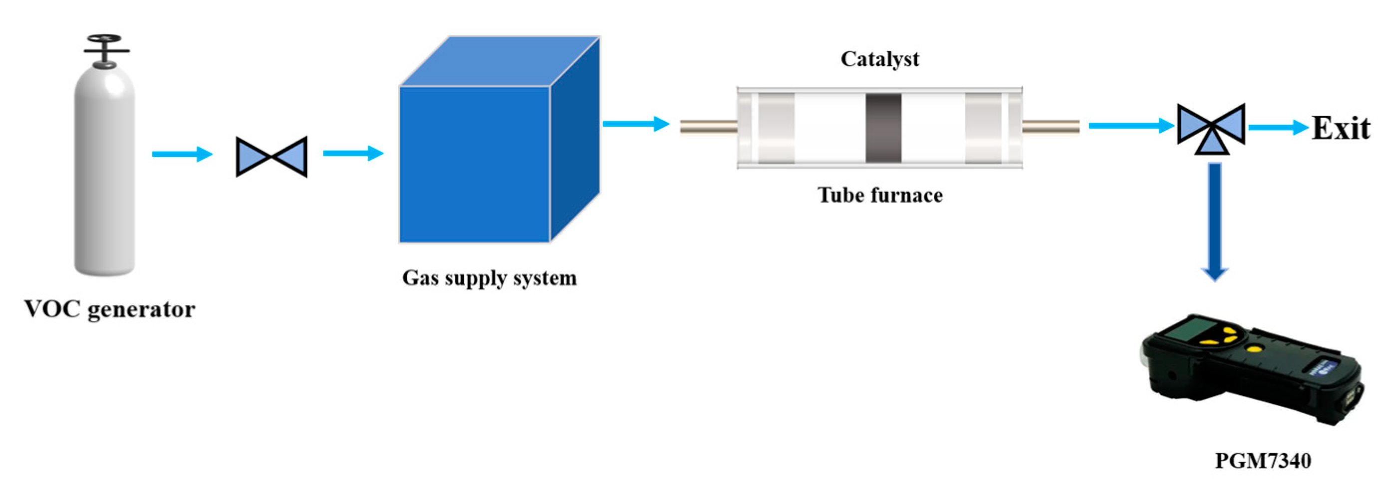
Figure 2 is a graphical representation of the toluene catalytic system. Air diluted toluene gas (101 ppm) from the storage tank is fed into the gas supply system using a gas flow meter to maintain an inlet toluene concentration of 101 ppm when entering the tube furnace. The diluted toluene gas and the air are mixed in the gas supply system and then enter the stationary reactor. The diluted toluene gas entering the stationary reactor reacts with oxygen on the monolithic LaFeO3 catalyst. The rear gas was collected using a gas sampling bag. The toluene concentration for the inlet and outlet gas was measured using a Honeywell-Warren PGM-7340ppb RAE3000 VOC gas detector. The weight hourly space velocity of inlet toluene gas is 36,000 mL/(g∙h). The conversion of toluene can be calculated as follows:
φ(C7H8) (%) = 100 × ([C7H8]in − [C7H8]out)/[C7H8]in
where [C7H8]in (%) and [C7H8]out (%) denote the inlet and outlet toluene concentrations, respectively.

3. Results and Discussion

3.1. XRD Characterization

Figure 3 shows the powder X-ray diffraction patterns of the synthesized LaFeO3 powders at different calcination temperatures (500 °C, 600 °C, 700 °C and 800 °C). The XRD patterns match the standard diffraction pattern of the orthorhombic phase (JCPDS No. 74-2203). The sharp diffraction peaks indicate that LaFeO3 has a high crystallinity. No signals of other diffraction peaks were found, indicating that the LaFeO3 powders were successfully synthesized at these temperatures. The reflections located at 22.61°, 32.17°, 39.70°, 46.16°, 51.95°, 57.41°, 67.30° and 76.53° correspond to (002), (112), (022), (004), (114), (204), (040) and (116) reflection plane, respectively. Meanwhile, the X-ray diffraction patterns showed that the reflection peaks of LaFeO3 became sharper with the increase in calcination temperature, indicating improved crystallinity. According to Scherrer’s formula, the particle size of 500 LFO particles is 156 nm, the particle size of 600 LFO particles is 168 nm, the particle size of 700 LFO particles is 266 nm and the particle size of 800 LFO particles is 278 nm.

3.2. Morphology Analysis

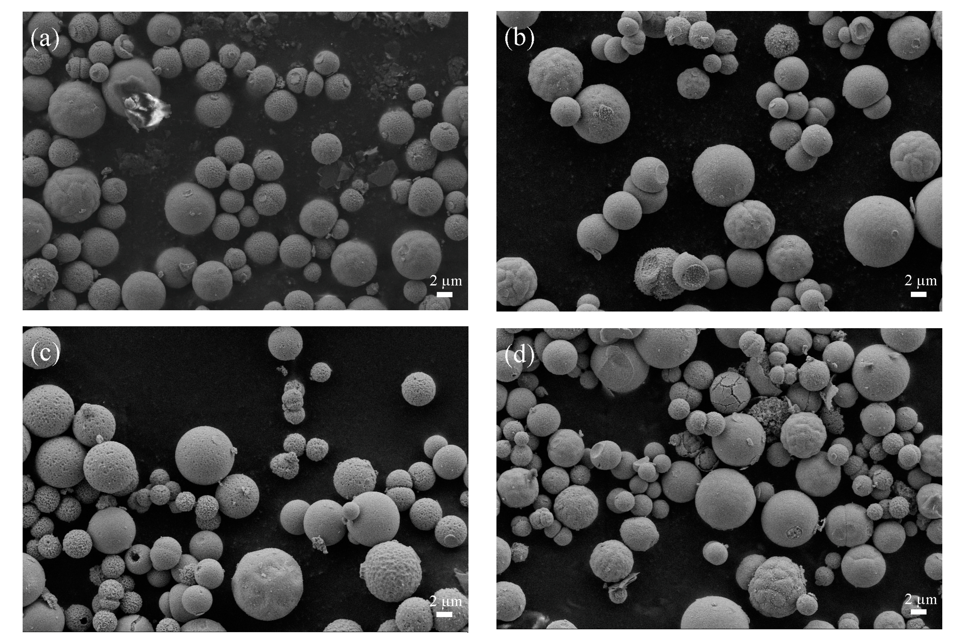
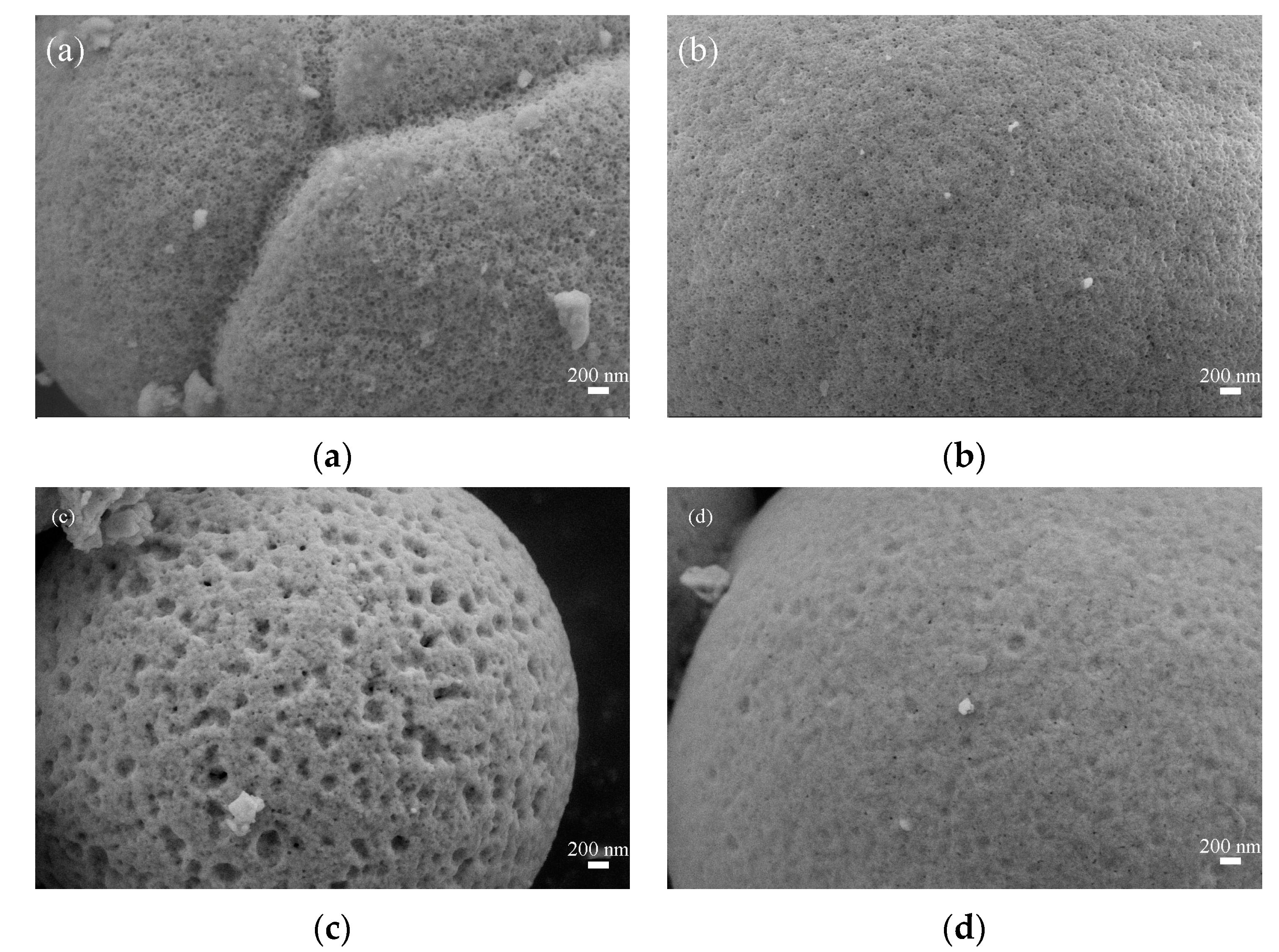
The morphological characteristics of the LaFeO3 powders were analyzed by SEM. Figure 4 and Figure 5 show the 5000 and 50,000 magnification images of LaFeO3 synthesized at different calcination temperatures. Figure 4 shows that the morphology of LaFeO3 synthesized at four temperatures is characterized by spherical particles about 2–3 μm in diameter with pits and pores on the surface. The grain size derived from the SEM image is basically the same as that calculated earlier. It can be seen from Figure 5 that with the increase in calcination temperature, the surfaces of microspheres gradually become smooth and flat, the pore size becomes smaller and the number of pores increases. When the calcination temperature increases to 800 °C, the surface of microspheres gradually becomes smooth, the pores gradually decrease and it can be clearly observed that the calcination temperature changes the morphological structure of these microspheres.

3.3. BET Measurements

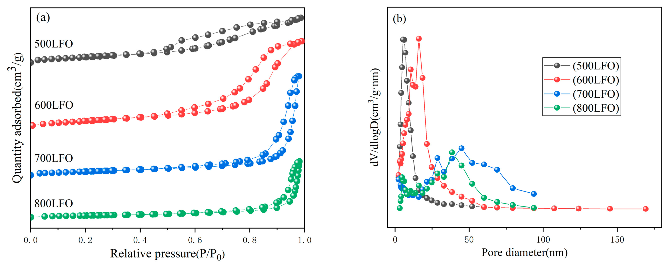
In order to investigate the effect of calcination temperature on the specific surface area and pore size distribution of LaFeO3, the prepared catalysts were tested for N2 adsorption–desorption. The nitrogen adsorption–desorption curves and BJH pore size distribution curves are shown in Figure 6, and the specific data are shown in Table 1. The nitrogen adsorption–desorption curves of the LaFeO3 catalysts are type IV isothermal curves with H4−type hysteresis loops, and the pore size distribution plots better prove the existence of mesoporous structures for the four of LaFeO3 catalysts [37]. For the other three catalyst groups, 700 LFO has the largest specific surface area, followed by 600 LFO. The pore size distribution of the four LaFeO3 catalysts was found to be in a wide range based on the Barrett–Joyner–Halenda (BJH) method calculation in Figure 6b, with the pore size of the 500 LFO catalyst being around 2.7–52 nm, the 600 LFO catalyst being around 2.7–170 nm, the 700 LFO catalyst being around 2.7–52 nm and the pore size of the 800 LFO catalyst around 2.2–93 nm. It is well known that the specific surface area size of catalysts has a large influence on the catalytic activity, and a larger specific surface area exposes more active sites on the surface, prompting more pollutant molecules to be adsorbed on the catalyst surface. The results showed that 700 LFO had the largest specific surface area of 23.41 m2/g.

3.4. Structural Composition Analysis of Materials

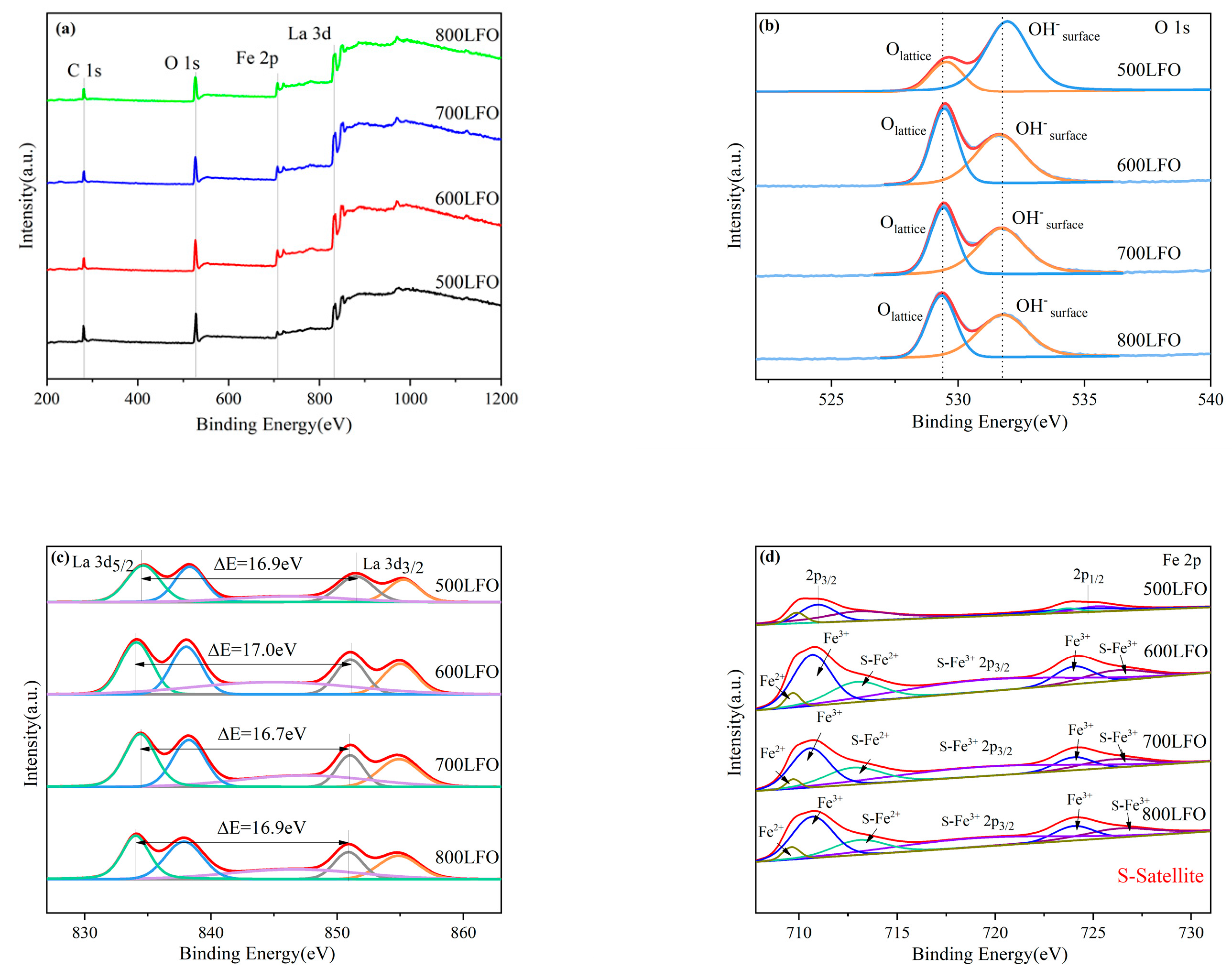
In order to determine the surface elemental composition and oxidation state of several samples, surface X-ray photoelectron spectroscopy was performed to analyze the LaFeO3. Figure 7 shows the full XPS spectra of synthetic LaFeO3 at different calcination temperatures (Figure 7a) and narrow spectra of O1s, Fe 2p and La 3d energy levels (Figure 7b–d). In addition, the C 1s binding energy of 284.8 eV is often used as a charge correction for other elements [38].
The high−resolution spectra of O 1s are shown in Figure 7b. For 500 LFO, the binding energy at 529.6 eV and 531.9 eV is assigned to lattice oxygen (La-O and Fe-O) and adsorbed oxygen on the surface of chemically absorbed hydroxyl or carbonate groups [39,40]. For 600 LFO, the binding energy at 529.5 eV and 531.8 eV is assigned to lattice oxygen (La-O and Fe-O) and adsorbed oxygen on the surface of chemically absorbed hydroxyl or carbonate groups. For 700 LFO, the binding energy at 529.4 eV and 531.7 eV is assigned to lattice oxygen (La-O and Fe-O) and adsorbed oxygen on the surface of chemically absorbed hydroxyl or carbonate groups. For 800 LFO, the binding energy at 529.3 eV and 531.6 eV binding energy is assigned to lattice oxygen (La-O and Fe-O) and adsorbed oxygen on the surface of chemically absorbed hydroxyl or carbonate groups. Comparing the four catalysts, the binding energy peak of O 1s shifts to lower binding energy with increasing calcination temperature, which proves that oxygen ions contribute significantly to the electron transfer within LaFeO3 [41]. Among the four LaFeO3 catalysts, 700 LFO has a higher Oads (adsorbed oxygen)/Olatt (surface lattice oxygen) value (1.62), and the specific Oads/Olatt values are shown in Table 2.
In Figure 7c, the two sets of peaks in 500 LFO are at 834.6, 838.4 eV and 851.5, 855.2 eV, respectively, the two sets of peaks in 600 LFO are located at 834.2, 838.1 eV and 851.1, 855 eV, respectively, and the two sets of peaks in 700 LFO are at 834.3, 838.2 eV and 851, 854.9 eV, with the two sets of peaks in 500 LFO, 600 LFO and 700 LFO correlated with the spin-orbit splitting characteristic binding energy of La 3d5/2 and La 3d3/2 of La3+, while the peaks in La 3d5/2 and La 3d3/2 of 800 LFO are located at 834, 837.8 eV and 850.9, 854.8 eV. These two correlated peaks in each spin orbit are further split into two parts, attributed to the presence of energy loss phenomena or electron configuration mixtures caused by strong O 2p-La 4f charge events (“shock-excited” satellites) [42]. Moreover, the splitting voltages corresponding to 500 LFO, 600 LFO, 700 LFO and 800 LFO are 16.9 eV, 17 eV, 16.7 eV and 16.9 eV.
In the Fe 2p spectrum of Figure 7d, the peaks at 710.9 and 725.2 eV and two satellite peaks (714.9 and 722.4 eV) in the 500 LFO indicate the presence of Fe3+ in the LaFeO3, and the binding energies at 709.9 and 713.1 eV are consistent with the Fe2+ match in the LaFeO3. The two satellite peaks (716.1 and 723.1 eV) of the peak at 710.7 and 724.2 eV in 600 LFO indicate the presence of Fe3+ in LaFeO3, and the binding energy at 709.7 and 713.1 eV indicates the presence of Fe2+ in LaFeO3. The two satellite peaks of the peak at 710.6 and 724 eV (716.2 and 723 eV) in the 700 LFO indicate the presence of Fe3+ in the LaFeO3, and the characteristic binding energy at 709.7 and 712.9 eV indicates the presence of Fe2+ in the LaFeO3. The two satellite peaks of the peak at 710.7 and 724.2 eV in the 800 LFO (715.9 and 723.2 eV) indicate the presence of Fe3+ in the LaFeO3, and the characteristic binding energies at 709.6 and 713.2 eV indicate the presence of Fe2+ in the LaFeO3. This implies that two mixed Fe2+/Fe3+ states exist in the octahedra of LaFeO3 sharing prismatic positions, while the presence of Fe2+ oxidation states can be attributed to the generation of oxygen vacancies. In addition, the spin-orbit splitting of the 500 LFO, 600 LFO, 700 LFO and 800 LFO samples was 13.6 eV, 13.5 eV, 13.4 eV and 13.5 eV, respectively. Finally, the 700 LFO catalyst had the highest surface Fe2+/Fe3+ molar ratio (0.78), and the order of Fe2+/Fe3+ molar ratios for the four catalyst groups was: 700 LFO > 800 LFO > 600 LFO > 500 LFO. The specific Fe2+/Fe3+ molar ratios are shown in Table 2. From XPS, the content ratios of Fe, La and O in 500 LFO were 6.2%, 12.9% and 80.9%, respectively. The content ratios of Fe, La and O in 600 LFO were 11.1%, 15.4% and 73.5%, respectively. The content ratios of Fe, La and O in 700 LFO were 9.6%, 16.7% and 73.7%. The content ratios of Fe, La and O in 800 LFO were 11.2%, 14.7% and 74.1%, respectively.

3.5. Catalytic Performance

The catalytic performance of the prepared sets of monolithic catalysts for toluene was investigated below 450 °C. Figure 8a shows the performance of the four sets of monolithic LaFeO3 catalysts for toluene oxidation at a toluene concentration of 101 ppm and an air rate of 100 mL/min (WHSV = 36,000 mL/(g∙h)). Figure 8b shows the reaction temperatures corresponding to the conversion of toluene at 90% for the three LaFeO3 catalysts. It is well known that catalysts for catalytic oxidation performance of gases are usually evaluated using T10%, T50% and T90% (corresponding to the reaction temperatures required to reach 10%, 50% and 90% toluene conversions).
According to Figure 8a, the monolithic catalysts with the addition of LaFeO3 all showed higher catalytic activity than the monolithic catalysts without the addition of LaFeO3. The catalytic activities of the monolithic catalysts with LaFeO3 were ranked as follows: 700 LFO > 800 LFO > 600 LFO > 500 LFO. Obviously, the monolithic catalysts without LaFeO3 did not show high degradation of toluene, and the thermal degradation of toluene was only 31.2% at 450 °C, while 700 LFO with LaFeO3 catalyst showed the best catalytic activity for toluene with T10%, T50% and T90% of 76 °C, 253 °C and 420 °C, respectively, which were 7 °C, 32 °C and 30 °C lower than those of 600 LFO with T10%, T50% and T90%, respectively. Table 3 shows the reaction temperatures of the monolithic catalyst with and without the addition of LaFeO3 at 10%, 50% and 90% conversion of toluene. Undoubtedly, the specific surface area, pore structure, surface active center and surface adsorbed oxygen concentration of the catalysts are significantly related to their catalytic activity. From the experimental data and characterization, it is clear that 700 LFO has the largest specific surface area, the most active centers and the most abundant surface adsorbed oxygen concentration compared to 500 LFO, 600 LFO and 800 LFO, which results in better catalytic performance in the toluene oxidation experiments.
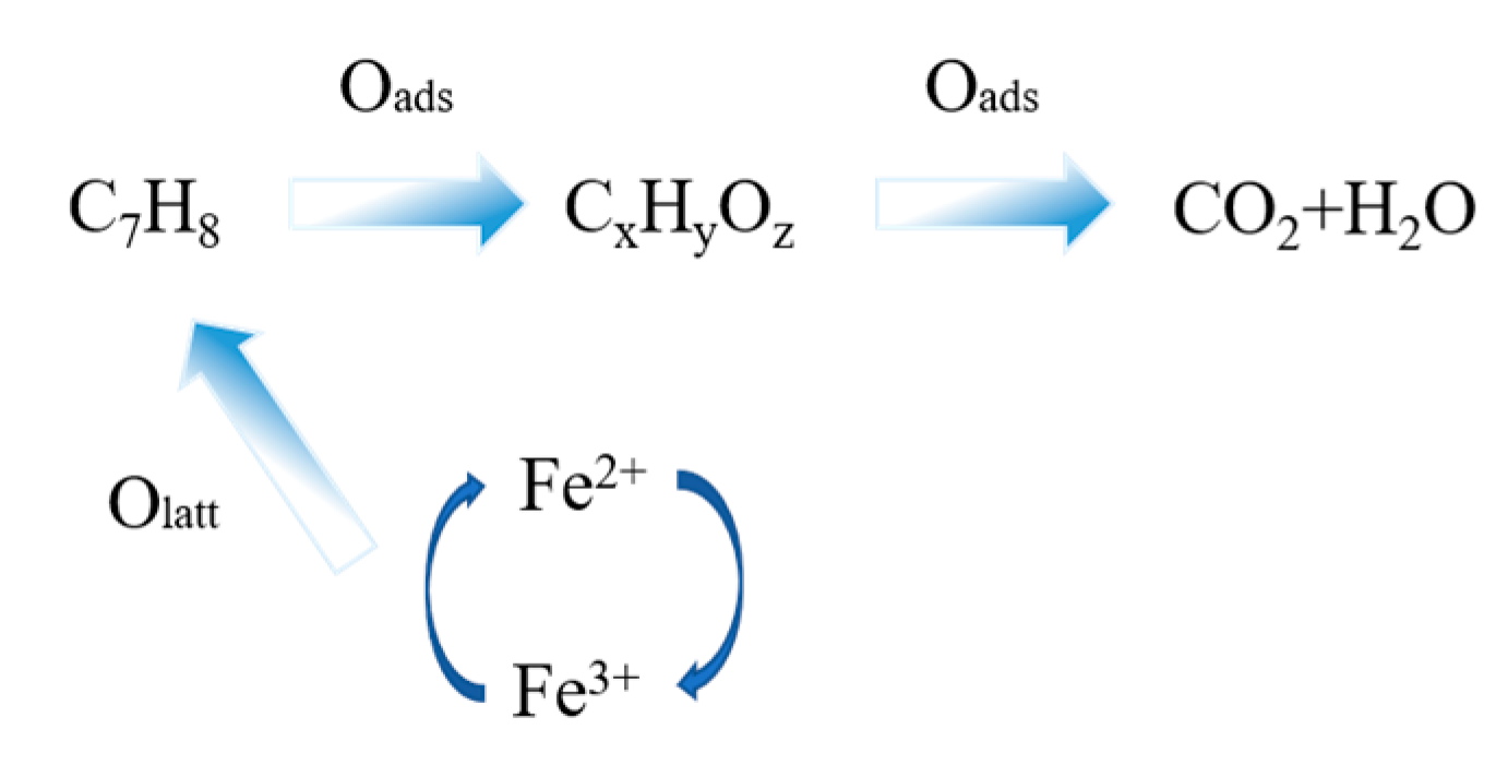
Figure 9 demonstrates the reaction mechanism of catalytic oxidation of toluene gas by the LaFeO3 catalyst. Fe2+ is trapped by oxygen molecules when transferring electrons, and oxygen molecules are adsorbed to oxygen vacancies and activated. Negatively charged oxygen anions (O, O2−) fill the oxygen vacancies and provide oxygen resources for the catalytic reaction. At the same time, the transfer of electrons leads to the transformation of Fe2+ to Fe3+. Toluene molecules are adsorbed on Fe3+, and the coordination between them allows electrons to be transferred from the toluene to the Fe3+ position. Regeneration of Fe2+ and positively charged toluene occurs due to electron transfer. Negatively charged oxygen and positively charged toluene react to produce carbon dioxide and water through the breaking of old chemical bonds and the formation of new ones [43].

4. Conclusions

Porous powder LaFeO3 was readily prepared using the conventional high temperature calcination of precursors obtained from hydrothermal syntheses. Finally, the honeycomb LaFeO3 catalysts were prepared by the one-shot molding method. From the experimental results, it was shown that the calcination temperature from 500 °C to 800 °C had a significant effect on the morphology, structure, specific surface area and the concentration of adsorbed oxygen on the surface of the LaFeO3 catalysts. According to the SEM results, comparing the morphology of the other three groups of LaFeO3 catalysts, the 700 LFO catalyst has more pits on the surface, forming more pores and smaller pores, resulting in more active sites exposed on the catalyst surface, which has a greater impact on the performance of the porous catalyst. Among the prepared groups of LaFeO3 catalysts, 700 LFO showed the largest specific surface area (23.41 m2/g), the more abundant concentration of surface adsorbed oxygen as well as the best catalytic performance for toluene (T10%, T50% and T90% at a toluene concentration of 101 ppm and an air rate of 100 mL/min (WHSV = 36,000 mL/(g∙h)), respectively 76 °C, 253 °C and 420 °C).

Author Contributions

Conceptualization, Z.P.; software, Y.L. (Yunfei Liu) and Y.L. (Yinong Lu); data curation, S.H.; writing—original draft preparation, S.H.; writing—review and editing, Z.P. and Y.T. All authors have read and agreed to the published version of the manuscript.

Funding

This research was funded by Priority Academic Program Development (PAPD) of Jiangsu Higher Education Institutions, P. R. China.

Institutional Review Board Statement

Not applicable.

Informed Consent Statement

Not applicable.

Data Availability Statement

The data presented in this study are available on request from the corresponding author.

Acknowledgments

The authors gratefully acknowledge the assistance from Zhigang Pan and Yaqiu Tao from NJTECH, and the staff from State Key Laboratory of Materials-Oriented Chemical Engineering.

Conflicts of Interest

The authors declare no conflict of interest.

References

  1. Morales Torres, S.; Carrasco Marin, F.; Perez Cadenas, A.F. Coupling Noble Metals and Carbon Supports in the Development of Combustion Catalysts for the Abatement of BTX Compounds in Air Streams. Catalysts 2015, 5, 0774. [Google Scholar] [CrossRef]
  2. Li, W.B.; Wang, J.X.; Gong, H. Catalytic combustion of VOCs on non-noble metal catalysts. Catal. Today 2009, 148, 81–87. [Google Scholar] [CrossRef]
  3. Qiu, K.; Yang, L.; Lin, J. Historical industrial emissions of non-methane volatile organic compounds in China for the period of 1980–2010. Atmos. Environ. 2014, 86, 102–112. [Google Scholar] [CrossRef]
  4. Rajabi, H.; Hadi, M.M.; Mandal, P. Emissions of volatile organic compounds from crude oil processing–Global emission inventory and environmental release. Sci. Total Environ. 2020, 727, 138654. [Google Scholar] [CrossRef]
  5. Kamal, M.S.; Razzak, S.A.; Hossain, M.M. Catalytic oxidation of volatile organic compounds (VOCs)—A review. Atmos. Environ. 2016, 140, 117–134. [Google Scholar] [CrossRef]
  6. Thepanondh, S.; Varoonphan, J.; Sarutichart, P. Airborne Volatile Organic Compounds and Their Potential Health Impact on the Vicinity of Petrochemical Industrial Complex. Water Air Soil Pollut. 2011, 214, 83–92. [Google Scholar] [CrossRef]
  7. Luo, D.; Yi, P.; Chen, A. Indoor Pollution Caused by Building and Decorative Materials and Their Preventive Measure. China Saf. Sci. 2003, 13, 66–68. [Google Scholar]
  8. He, C.; Cheng, J.; Zhang, X. Recent Advances in the Catalytic Oxidation of Volatile Organic Compounds: A Review Based on Pollutant Sorts and Sources. Chem. Rev. 2019, 119, 4471–4568. [Google Scholar] [CrossRef]
  9. Mo, J.; Zhang, Y.; Xu, Q. Photocatalytic purification of volatile organic compounds in indoor air: A literature review. Atmos. Environ. 2009, 43, 2229–2246. [Google Scholar] [CrossRef]
  10. Li, G.S.; Zhang, D.Q.; Yu, J.C. An Efficient Bismuth Tungstate Visible-Light-Driven Photocatalyst for Breaking Down Nitric Oxide. Environ. Sci. Technol. 2010, 44, 4276–4281. [Google Scholar] [CrossRef]
  11. Morales-Torres, S.; Maldonado-Hódar, F.J.; Pérez-Cadenas, A.F.; Carrasco-Marín, F. Design of low-temperature Pt-carbon combustion catalysts for VOC’s treatments. J. Hazard. Mater. 2010, 183, 814–822. [Google Scholar] [CrossRef] [PubMed]
  12. Tsai, W.T. An overview of health hazards of volatile organic compounds regulated as indoor air pollutants. Rev. Environ. Health 2019, 34, 81–89. [Google Scholar] [CrossRef] [PubMed]
  13. Niu, Q.; Li, B.; Xu, X. Research progress in catalytic combustion of volatile organic compounds. Mod. Chem. Ind. 2013, 33, 19–23. [Google Scholar]
  14. Hongyan, P.A.N.; Yu, Z.; Qian, L.I.N. Advance in non-noble metal catalysts for catalytic combustion of volatile organic compounds. Chem. Ind. Eng. Prog. 2011, 30, 1726–1732, 1748. [Google Scholar]
  15. Wang, C.C.; Li, J.R.; Lv, X.L. Photocatalytic organic pollutants degradation in metal-organic frameworks. Energy Environ. Sci. 2014, 7, 2831–2867. [Google Scholar] [CrossRef]
  16. Zhao, X.X.; Li, J.Z.; Li, X. Design of metal-organic frameworks (MOFs) -based photocatalyst for solar fuel production and photo-degradation of pollutants. Chin. J. Catal. 2021, 42, 872–903. [Google Scholar] [CrossRef]
  17. Busca, G.; Berardinelli, S.; Resini, C. Technologies for the removal of phenol from fluid streams: A short review of recent developments. J. Hazard. Mater. 2008, 160, 265–288. [Google Scholar] [CrossRef]
  18. Shou, T.; Li, Y.; Bernards, M.T. Degradation of gas-phase o-xylene via combined non-thermal plasma and Fe doped LaMnO3 catalysts: Byproduct control. J. Hazard. Mater. 2020, 387, 121750. [Google Scholar] [CrossRef]
  19. Hosseini, S.A.; Sadeghi, M.T.; Alemi, A. Synthesis, Characterization, and Performance of LaZnxFe1−xO3 Perovskite Nanocatalysts for toluene combustion. Chin. J. Catal. 2010, 31, 747–750. [Google Scholar] [CrossRef]
  20. Lv, Y.; Cheng, B.; Yang, H. Chemical looping partial oxidation (CLPO) of toluene on LaFeO3 perovskites for tunable syngas production. Chem. Eng. J. 2023, 451, 138968. [Google Scholar] [CrossRef]
  21. Tarjomannejad, A.; Farzi, A.; Niaei, A. An experimental and kinetic study of toluene oxidation over LaMn1−xBxO3 and La0.8A0.2Mn0.3B0.7O3 (A = Sr, Ce and B = Cu, Fe) nano-perovskite catalysts. Korean J. Chem. Eng. 2016, 33, 2628–2637. [Google Scholar] [CrossRef]
  22. Zhao, L.; Jiang, L.; Huang, Y. Mechanism investigation of three-dimensional porous A-site substituted La1−xCoxFeO3 catalysts for simultaneous oxidation of NO and toluene with H2O. Appl. Surf. Sci. 2022, 578, 151977. [Google Scholar] [CrossRef]
  23. Penuelas, J.; Asensio, D.; Tholl, D. Biogenic volatile emissions from the soil. Plant Cell Environ. 2014, 37, 1866–1891. [Google Scholar] [CrossRef]
  24. Kim, H.S.; Kim, H.J.; Kim, J.H. Noble-Metal-Based Catalytic Oxidation Technology Trends for Volatile Organic Compound (VOC) Removal. Catalysts 2022, 12, 63. [Google Scholar] [CrossRef]
  25. Wu, P.; Jin, X.; Qiu, Y. Recent Progress of Thermocatalytic and Photo/Thermocatalytic Oxidation for VOCs Purification over Manganese-based Oxide Catalysts. Environ. Sci. Technol. 2021, 55, 4268–4286. [Google Scholar] [CrossRef]
  26. Tang, Y.; Tao, Y.; Zhou, T. Direct Z-scheme La1−xCexMnO3 catalyst for photothermal degradation of toluene. Environ. Sci. Pollut. Res. 2019, 26, 36832–36844. [Google Scholar] [CrossRef]
  27. Padilla, O.; Munera, J.; Gallego, J. Approach to the Characterization of Monolithic Catalysts Based on La Perovskite-like Oxides and Their Application for VOC Oxidation under Simulated Indoor Environment Conditions. Catalysts 2022, 12, 168. [Google Scholar] [CrossRef]
  28. Gao, B.; Deng, J.; Liu, Y. Mesoporous LaFeO3 catalysts for the oxidation of toluene and carbon monoxide. Chin. J. Catal. 2013, 34, 2223–2229. [Google Scholar] [CrossRef]
  29. Zhao, S.; Wang, L.; Wang, Y. Hierarchically porous LaFeO3 perovskite prepared from the pomelo peel bio-template for catalytic oxidation of NO. J. Phys. Chem. Solids 2018, 116, 43–49. [Google Scholar] [CrossRef]
  30. Kajama, M.N.; Shehu, H.; Okon, E. VOC oxidation in excess of oxygen using flow-through catalytic membrane reactor. Int. J. Hydrogen Energy 2016, 41, 16529–16534. [Google Scholar] [CrossRef]
  31. Wu, M.; Chen, S.; Xiang, W. Oxygen vacancy induced performance enhancement of toluene catalytic oxidation using LaFeO3 perovskite oxides. Chem. Eng. J. 2020, 387, 124101. [Google Scholar] [CrossRef]
  32. Kumar, M.; Thapa, K.B.; Singh, P. Long-range surface plasmon resonance biosensors with cytop/Al/Perovskite and cytop/Al/MoS2 configurations. Phys. Scr. 2022, 97, 055501. [Google Scholar] [CrossRef]
  33. Ayesh, A.I.; Alghamdi, S.A.; Salah, B. High sensitivity H2S gas sensors using lead halide perovskite nanoparticles. Results Phys. 2022, 35, 105333. [Google Scholar] [CrossRef]
  34. Lee, K.Y.; Hsieh, J.C.; Chen, C.A. Ultrasensitive detection of hydrogen sulfide gas based on perovskite vertical channel chemo-sensor. Sens. Actuators B Chem. 2021, 326, 128988. [Google Scholar] [CrossRef]
  35. Orera, A.; Slater, P.R. New Chemical Systems for Solid Oxide Fuel Cells. Chem. Mater. 2009, 22, 675–690. [Google Scholar] [CrossRef]
  36. Azalim, S.; Brahmi, R.; Agunaou, M. Washcoating of cordierite honeycomb with Ce-Zr-Mn mixed oxides for VOC catalytic oxidation. Chem. Eng. J. 2013, 223, 536–546. [Google Scholar] [CrossRef]
  37. Thommes, M.; Kaneko, K.; Neimark, A.V. Physisorption of gases, with special reference to the evaluation of surface area and pore size distribution. Pure Appl. Chem. 2015, 87, 1051–1069. [Google Scholar] [CrossRef]
  38. Guo, Y.; Chen, C.; Ling, L. Visible-light-driven photo-Fenton degradation of ceftriaxone sodium using SnS2/LaFeO3 composite photocatalysts. New J. Chem. 2021, 45, 18933–18946. [Google Scholar] [CrossRef]
  39. Wang, X.T.; Li, Y.; Zhang, X.Q. Design and fabrication of NiS/LaFeO3 heterostructures for high efficient photodegradation of organic dyes. Appl. Surf. Sci. 2020, 504, 144363. [Google Scholar] [CrossRef]
  40. Manchala, S.; Gandamalla, A.; Vempuluru, N.R. High potential and robust ternary LaFeO3/CdS/carbon quantum dots nanocomposite for photocatalytic H2 evolution under sunlight illumination. J. Colloid Interface Sci. 2021, 583, 255–266. [Google Scholar] [CrossRef]
  41. Wiranwetchayan, O.; Promnopas, S.; Phadungdhitidhada, S. Characterization of perovskite LaFeO3 synthesized by microwave plasma method for photocatalytic applications. Ceram. Int. 2019, 45, 4802–4809. [Google Scholar] [CrossRef]
  42. Lv, C.; Chen, H.; Hu, M. Nano-oxides washcoat for enhanced catalytic oxidation activity toward the perovskite-based monolithic catalyst. Environ. Sci. Pollut. Res. 2021, 28, 37142–37157. [Google Scholar] [CrossRef] [PubMed]
  43. Cui, X.; Yang, H.; Zhang, J. Characterization and performance of Ca-substituted La1−xCaxCoO3−δ perovskite for efficient catalytic oxidation of toluene. Catal. Lett. 2021, 151, 3323–3333. [Google Scholar] [CrossRef]
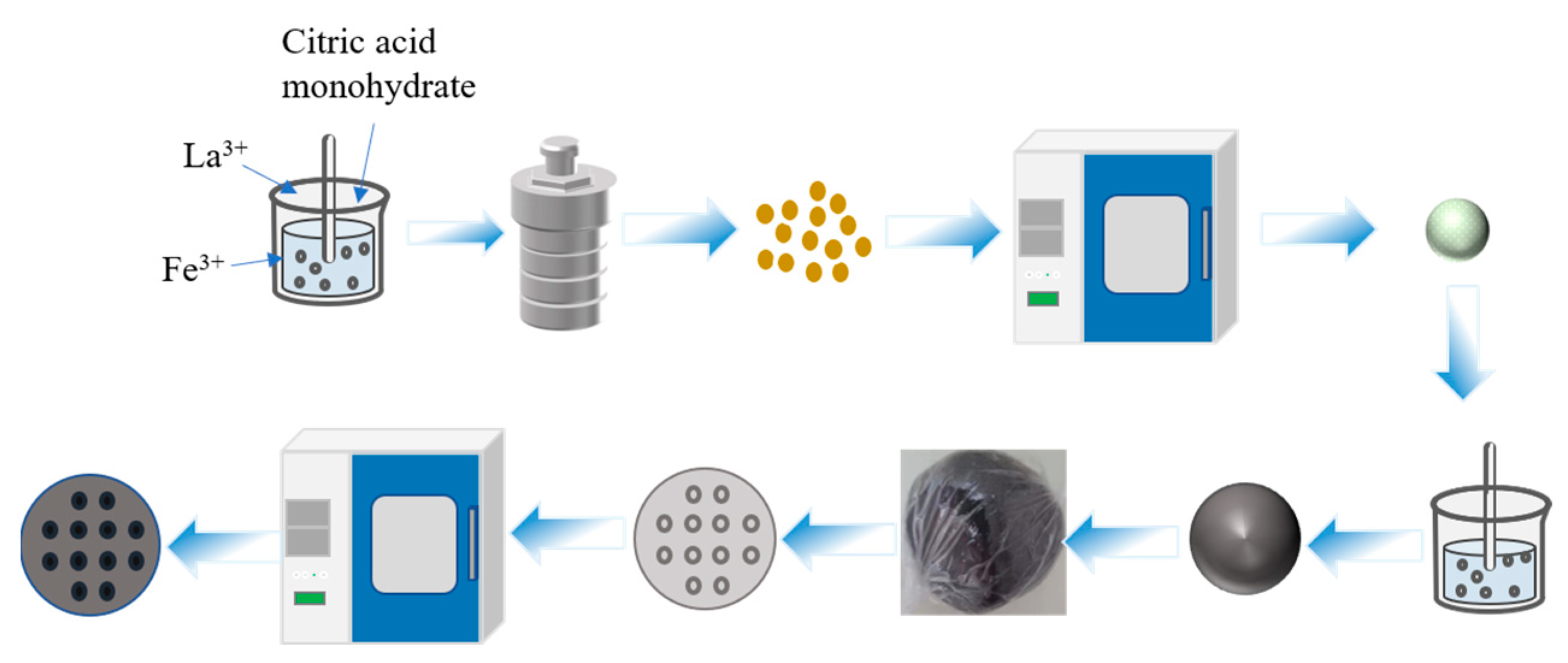
Figure 1. Preparation process of monolithic LaFeO3 catalysts.
Materials 16 03948 g001
Figure 2. Schematic diagram of catalytic oxidation of toluene.
Materials 16 03948 g002
Figure 3. Powder X-ray diffraction patterns of LaFeO3 powders calcinated at different temperatures.
Materials 16 03948 g003
Figure 4. Scanning electron microscope image of 500 LFO, 600 LFO, 700 LFO and 800 LFO catalysts at 5000 magnification; (a) 500 LFO, (b) 600 LFO, (c) 700 LFO and (d) 800 LFO.
Materials 16 03948 g004
Figure 5. Scanning electron microscope image of 500 LFO, 600 LFO, 700 LFO and 800 LFO catalysts at 50,000 magnification; (a) 500 LFO, (b) 600 LFO, (c) 700 LFO and (d) 800 LFO.
Materials 16 03948 g005
Figure 6. N2 adsorption–desorption isotherms (a) and pore size distribution curves (b) of LaFeO3 synthesized at different calcination temperatures.
Materials 16 03948 g006
Figure 7. XPS diagram of 500 LFO, 600 LFO, 700 LFO and 800 LFO catalysts, and (ad) show the complete XPS spectra, narrow spectra of O 1s, Fe 2p and La 3d energy levels of LaFeO3, respectively.
Materials 16 03948 g007
Figure 8. (a) Toluene conversions as function of reaction temperature over LaFeO3 perovskite catalysts sintered at different temperatures (b) The temperature required for each catalyst at a conversion of T90% for toluene.
Materials 16 03948 g008
Figure 9. Catalytic oxidation of toluene mechanism diagram.
Materials 16 03948 g009
Table 1. BET analysis of LaFeO3 synthesized by different calcination temperatures.
CatalystsBET Surface
Area (m2/g)
Average Pore
Size (nm)
Total Pore Volume
(cm3/g)
500 LFO13.428.990.04
600 LFO18.9113.660.08
700 LFO23.4127.320.09
800 LFO6.0333.120.05
Table 2. XPS parameters of different elements in LaFeO3 catalysts synthesized at different calcination temperatures.
Catalysts Binding Energy (eV)
La3+La3+Fe3+Fe3+Fe2+OadsOlattFe2+/Fe3+Oads/Olatt
3d 5/23d 3/22p 3/22p 1/22p 3/21 s1 s
500 LFO834.2/838.4851.5/855.2710.9/719.8724.5/725.5709.9/713.1529.6531.90.682.63
600 LFO834.1/838.1851.1/855710.7/719.5724.2/726.3709.7/713.1529.5531.80.701.21
700 LFO834.3/838.2851/854.9710.6/719.3724/726.5709.7/712.9529.4531.70.781.62
800 LFO834/837.8850.9/854.8710.7/719.1724.2/726.7709.6/713.2529.3531.60.711.26
Oads stands for adsorbed oxygen. Olatt stands for surface lattice oxygen.
Table 3. Reaction temperature of the different LaFeO3 catalyst for toluene conversion up to T90%.
CatalystsToluene Oxidation Activity (°C)
T10%T50%T90%
500 LFO87383/
600 LFO83285450
700 LFO76253420
800 LFO79259436
Without catalyst241//
Disclaimer/Publisher’s Note: The statements, opinions and data contained in all publications are solely those of the individual author(s) and contributor(s) and not of MDPI and/or the editor(s). MDPI and/or the editor(s) disclaim responsibility for any injury to people or property resulting from any ideas, methods, instructions or products referred to in the content.