Article

Modeling Analysis of a Polygeneration Plant Using a CeO2/Ce2O3 Chemical Looping

1
Department of Energy (DENERG), Politecnico di Torino, Corso Duca Degli Abruzzi, 24, 10129 Turin, Italy
2
Energy Center, Politecnico di Torino, Via Borsellino 38/18, 10129 Turin, Italy
*
Author to whom correspondence should be addressed.
Materials 2023, 16(1), 315; https://doi.org/10.3390/ma16010315
Submission received: 29 September 2022 / Revised: 28 November 2022 / Accepted: 22 December 2022 / Published: 29 December 2022

Abstract

:
In the current context of complexity between climate change, environmental sustainability, resource scarcity, and geopolitical aspects of energy resources, a polygenerative system with a circular approach is considered to generate energy (thermal, electrical, and fuel), contributing to the control of CO2 emissions. A plant for the multiple productions of electrical energy, thermal heat, DME, syngas, and methanol is discussed and analyzed, integrating a chemical cycle for CO2/H2O splitting driven using concentrated solar energy and biomethane. Two-stage chemical looping is the central part of the plant, operating with the CeO2/Ce2O3 redox couple and operating at 1.2 bar and 900 °C. The system is coupled to biomethane reforming. The chemical loop generates fuel for the plant’s secondary units: a DME synthesis and distillation unit and a solid oxide fuel cell (SOFC). The DME synthesis and distillation unit are integrated with a biomethane reforming reactor powered by concentrated solar energy to produce syngas at 800 °C. The technical feasibility in terms of performance is presented in this paper, both with and without solar irradiation, with the following results, respectively: overall efficiencies of 62.56% and 59.08%, electricity production of 6.17 MWe and 28.96 MWe, and heat production of 111.97 MWt and 35.82 MWt. The fuel production, which occurs only at high irradiance, is 0.71 kg/s methanol, 6.18 kg/s DME, and 19.68 kg/s for the syngas. The increase in plant productivity is studied by decoupling the operation of the chemical looping with a biomethane reformer from intermittent solar energy using the heat from the SOFC unit.

1. Introduction

Greenhouse gas emissions, climate change, and carbon scarcity are serious problems that require a strong focus. The sixth assessment report by the IPCC has been published, in which the role of anthropogenic activities is updated [1,2]. To reduce this impact on the environment, it was decided to limit the increase in global average temperature to 1.5 °C above pre-industrial levels [3]. The power generation sector plays a key role in reducing greenhouse gas emissions [4,5]. The use of solar energy in power generation could be a key tool to limit the use of fossil fuels. Solar radiation is highly available, globally distributed, clean, and renewable. However, the intermittent nature and recurring mismatch between consumers and direct supply are the main factors limiting its expansion. These problems can be overcome by non-fossil solar fuels [6,7], which store solar energy [8]. In this paper, solar energy is stored using a mixture of carbon monoxide and hydrogen. This gas mixture can be used as a direct fuel in a gas turbine [9,10] and an internal combustion engine [11,12] or in a fuel cell to generate electricity [12]. Furthermore, the conversion of syngas into fuels and other chemicals makes it possible to produce carbon-neutral materials [13,14,15]. The production of dimethyl ether from syngas is becoming an increasingly attractive route. The scientific community regards DME as the fuel that could eliminate the dependence on fossil fuels [16]. This is due to its physical properties, which are very similar to those of liquefied petroleum gas (LPG, e.g., propane and butane), with a low environmental and health impact [17]. Moreover, DME distillation also produces methanol (CH3OH) after dimethyl ether synthesis from syngas [18]. The main methods for producing solar syngas are photobiological or photochemical conversion, thermochemical conversion, and electrochemical conversion. The first route occurs at relatively low temperatures by directly using solar energy from photons to power the process [19,20]. Electrochemical conversion processes consist of the co-electrolysis of CO2 and H2O in an electrolyzer that supplies electricity from photovoltaic systems or solar thermal power plants [21,22]. Thermochemical conversion processes use concentrating solar collectors (CSP) to concentrate solar radiation to a point where a receiver reactor is located [23,24]. The simplest thermochemical pathway for syngas production would be the direct one-step solar thermal dissociation of water and carbon dioxide (thermolysis). However, this route is not practical, because an extremely high temperature of more than 2200 °C is required and cannot be achieved, due to the limitations imposed by the reactor materials, the thermal losses, and the possible products recombination to avoid explosive mixtures [25,26,27,28]. One way to lower the reduction temperature is to use redox cycles [20,29]. Two phases characterize the basic and simplest thermochemical cycles [30,31,32], with overall efficiencies of around 40–50% [33,34]. Considering a metal oxide (MO) with different oxidation states, the two steps are shown in Figure 1:
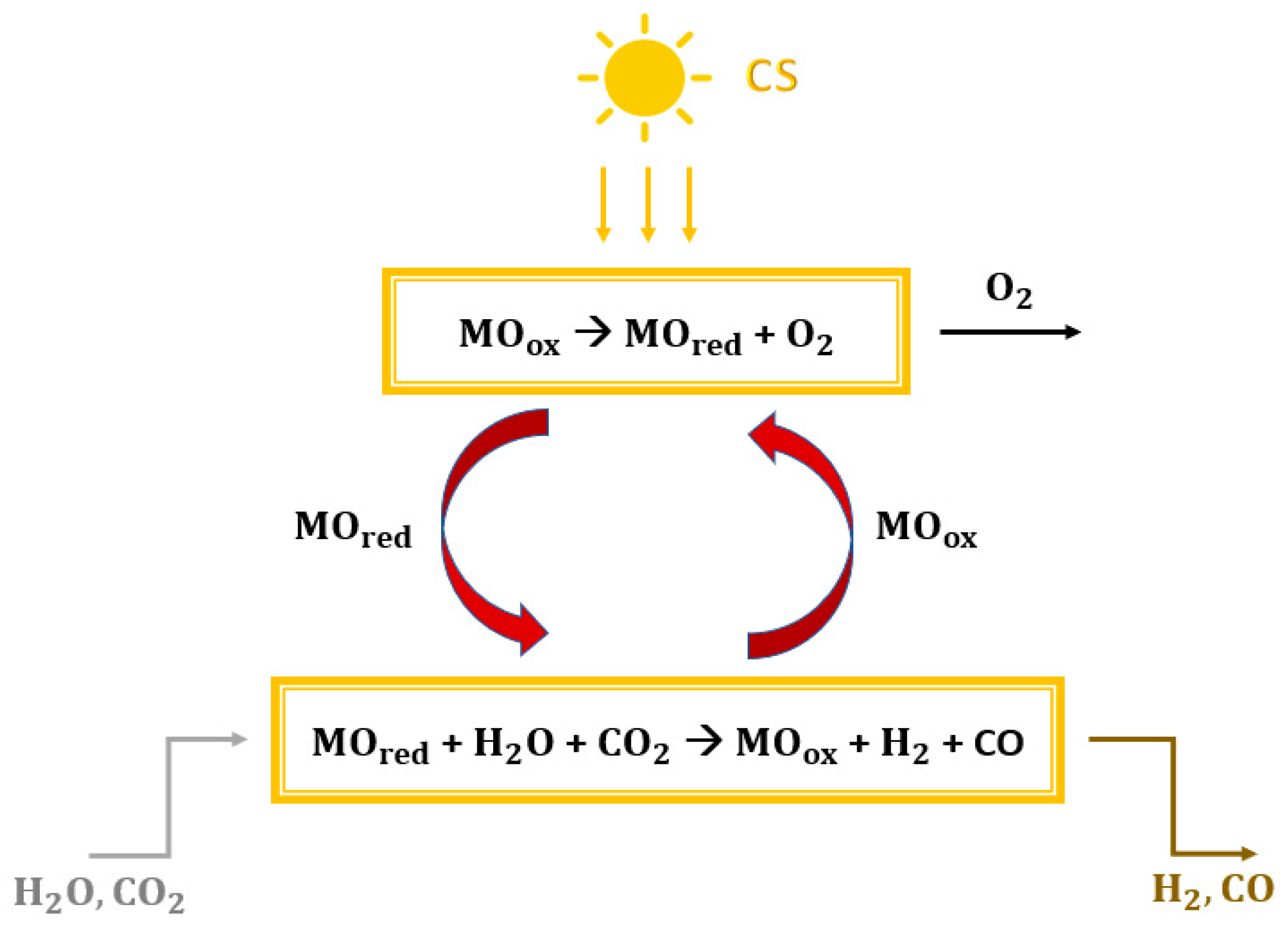
  • Reduction reaction (1): the concentrated solar energy provides thermal heat. The metal oxide MOox undergoes thermal reduction and releases oxygen (MOred is obtained).
  • Oxidation reaction (2): the reduced metal oxide MOred reacts with water and carbon dioxide to achieve both the reoxidation of metal and the reduction of H2O and CO2 with the subsequent production of syngas.
MOox → MOred + O2
MOred + H2O + CO2 → MOox + H2 + CO
Various metal-redox pairs have been investigated for the TSC processes. Ceria is currently considered the most attractive metal-redox pair for various reasons [35,36,37,38,39]: high crystallographic stability during extended thermal cycling (non-volatile cycle), high oxygen release and storage capacities (>100 mmol min−1 g−1), fast oxygen exchange rates, reversible shift between Ce4+ and Ce3+ oxidation states, and fast kinetics during thermochemical cycles as compared to other non-volatile metal oxides. However, the reduction reaction of pure ceria occurs only at very high temperatures (above 1400 °C) and very low pressures (between 100 and 200 mbar) [38]. The introduction of biomethane as a reducing agent (see Figure 2) could solve these problems [40,41,42,43] while preserving sustainability criteria, allowing the realization of an isothermal and isobaric cycle according to reactions (1) and (2).
(Reduction reaction)   2CeO2 + CH4 → CO + 2H2 + Ce2O3
(Oxidation reaction)   2Ce2O3 + CO2 + H2O → 4CeO2 + H2 + CO
Other thermochemical processes to produce syngas could be [25]: steam or dry natural gas/biomethane reforming [44], and biomass or coal gasification [45]. Biomethane could be produced by different separation mechanisms for upgrading the biogas extracted from the organic fraction of MSW (e.g., pressure swing adsorption, cryogenic separation, and absorption techniques [46]).
Polygeneration systems could represent an efficient and cost-effective solution for the integration of solar thermochemical conversion processes [47]. These systems have gained increasing attention in recent years due to their high overall efficiency and the possibility to use waste heat streams to generate useful heat or to obtain additional useful power [33,48]. As a result, these solutions generate multiple products such as electricity, cooling, heat, freshwater, and chemicals from one or more input streams in a single system. Several examples of polygeneration systems integrated with solar thermochemical conversion units can be found in the literature. Kaniyal et al. [49] performed a polygeneration system analysis based on hybrid solar gasification of coal at atmospheric pressure to produce liquid fuels and electricity. To solve the problem of intermittent solar energy, they proposed the pressurized storage of upgraded syngas and oxygen that can be used during periods of low solar radiation. Liu et al. [50] conducted a thermodynamic study on a lignite polygeneration system powered by solar energy. They demonstrated that the use of solar energy in lignite drying pyrolysis and gasification can save 63.84% of lignite energy compared to conventional methods. Kong et al. studied a polygeneration plant based on an isothermal thermochemical cycle fed with concentrated solar energy and methane to produce electricity and methanol simultaneously. They found that the fossil fuel consumption to produce one unit mass of methanol was about 22 GJ/ton with an optimum efficiency of more than 44%. Bai et al. [51] carried out a techno-economic analysis of a polygeneration system based on solar thermal gasification of biomass to produce methanol and electricity. They concluded that the energy and exergy efficiencies could reach values of 56.09% and 54.86%, respectively.
All literature studies are characterized by the production of CO2 streams, making the system not exactly carbon neutral. These gas streams could be emitted into the atmosphere without proper and accurate carbon capture and sequestration processes.
As far as we know, there are no studies on zero-emissions polygeneration plants at an industrial scale. In this paper, a polygeneration system with the solar-driven thermochemical cycle is simulated, analyzed, and discussed.

2. Case Study: Polygeneration Plant

The plant is built with four units:
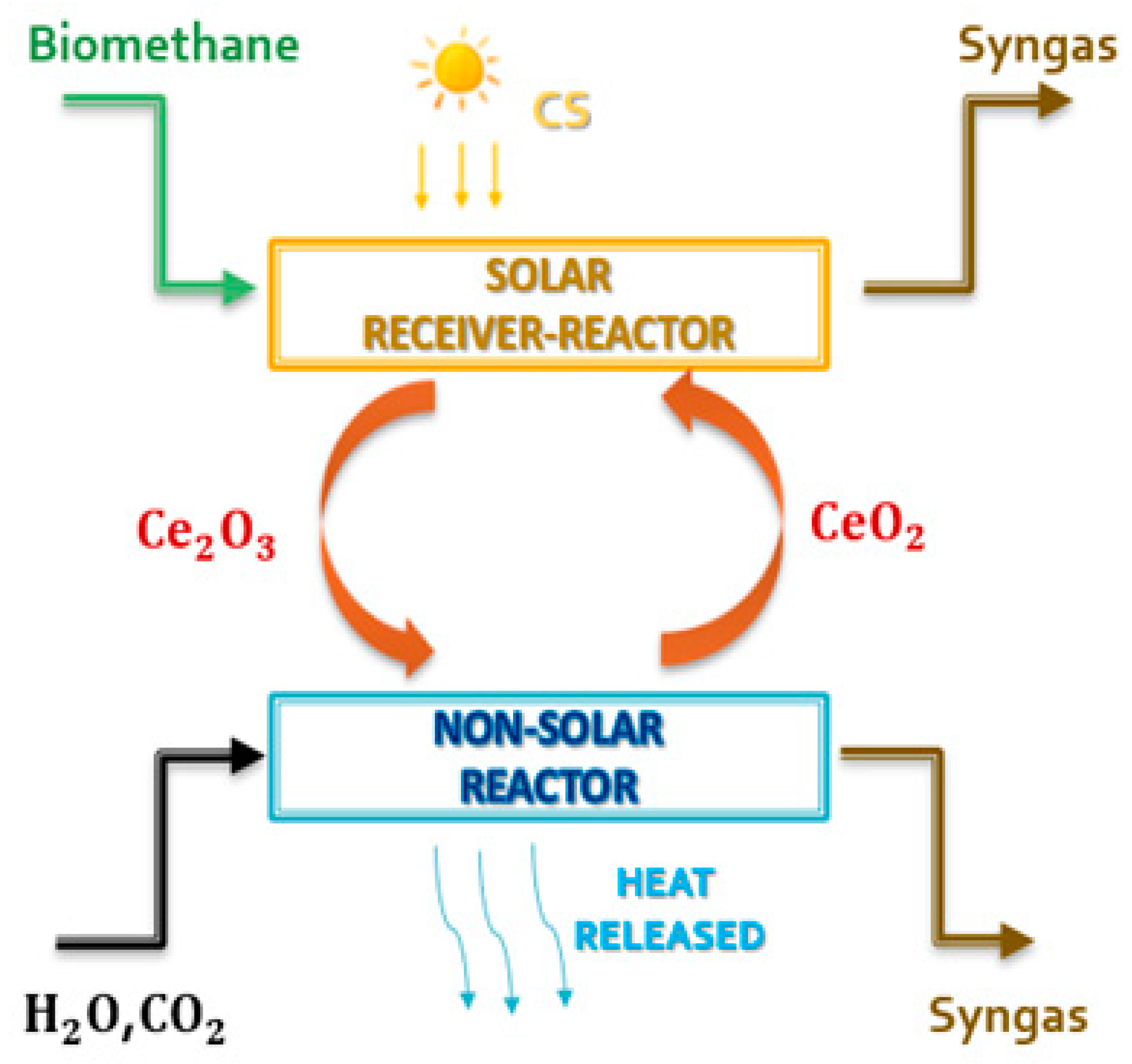
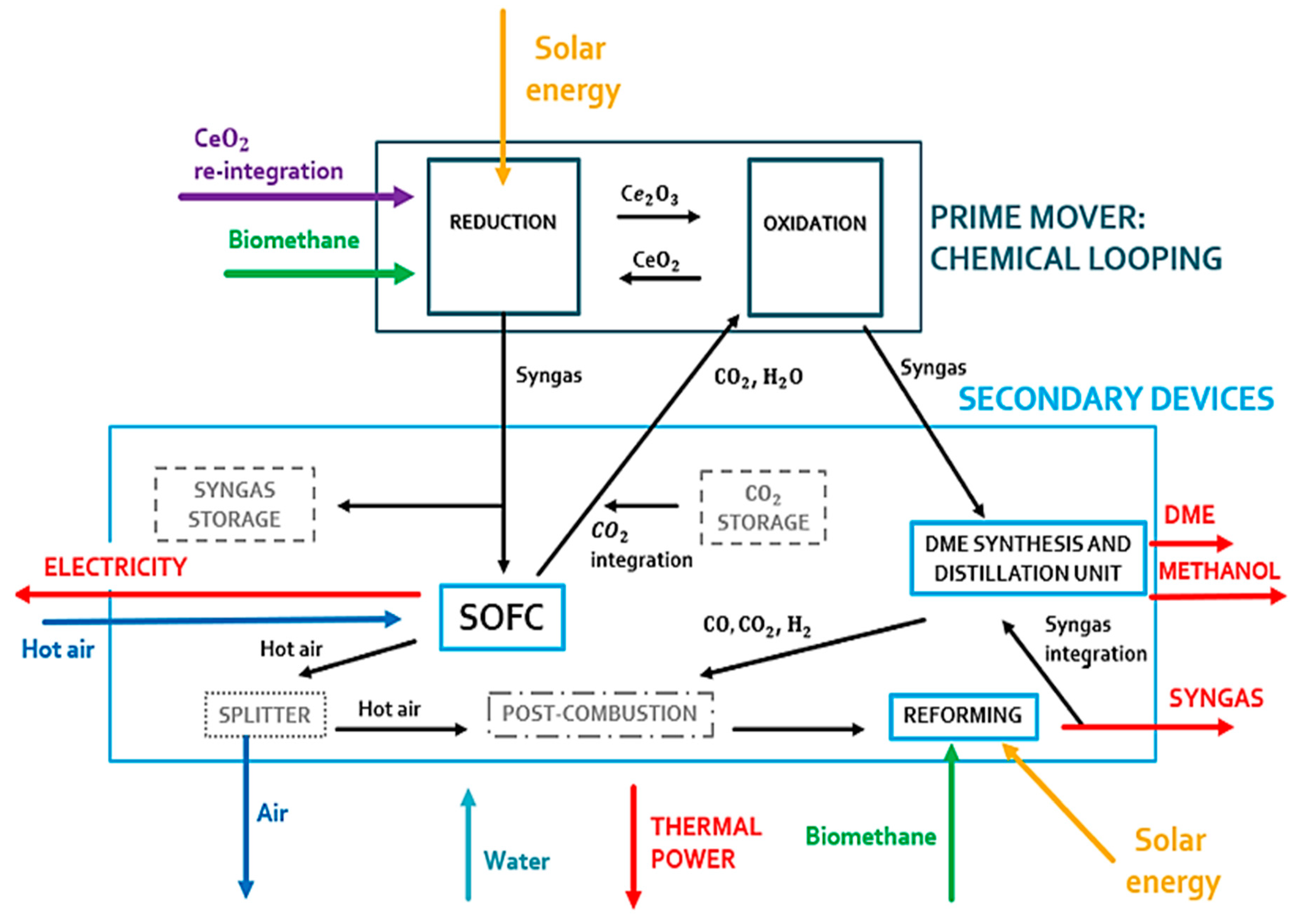
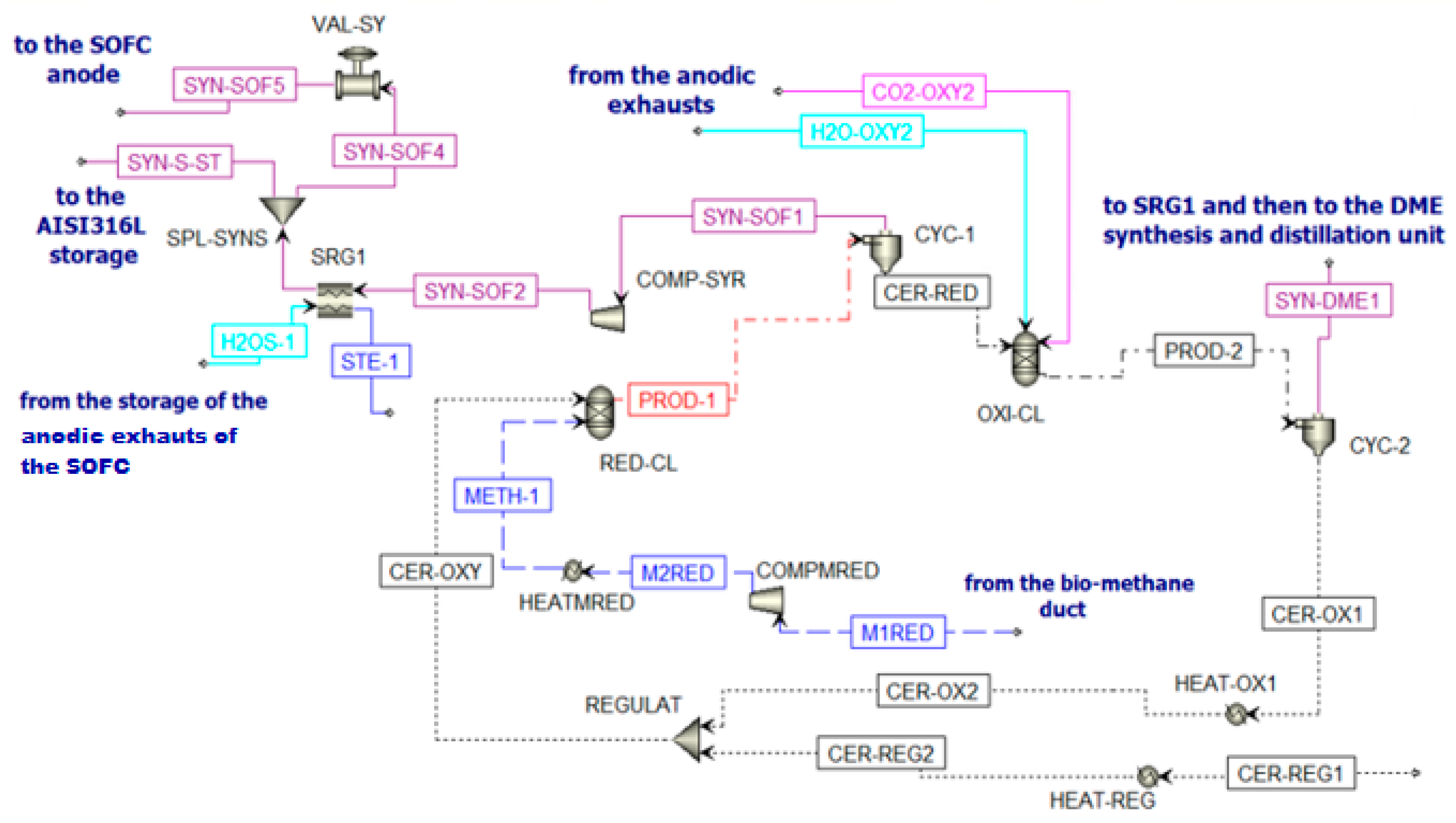
  • Chemical looping unit. This section is the driving force of the plant and produces the fuel for the other units. The CeO2/Ce2O3 redox couple associated with biomethane reforming is chosen (Figure 2). The cycle is unpressurized and isothermal at 900 °C and 1.2 bar. The reduction reaction takes place within a solar receiver via a solar tower, while the oxidation reaction takes place in a non-solar reactor. These two reactors operate simultaneously when solar energy is available. Under steady-state conditions, the reduction reactor is fed with 0.59 kmol/s of ceria with a particle size of 0.4–1 mm;
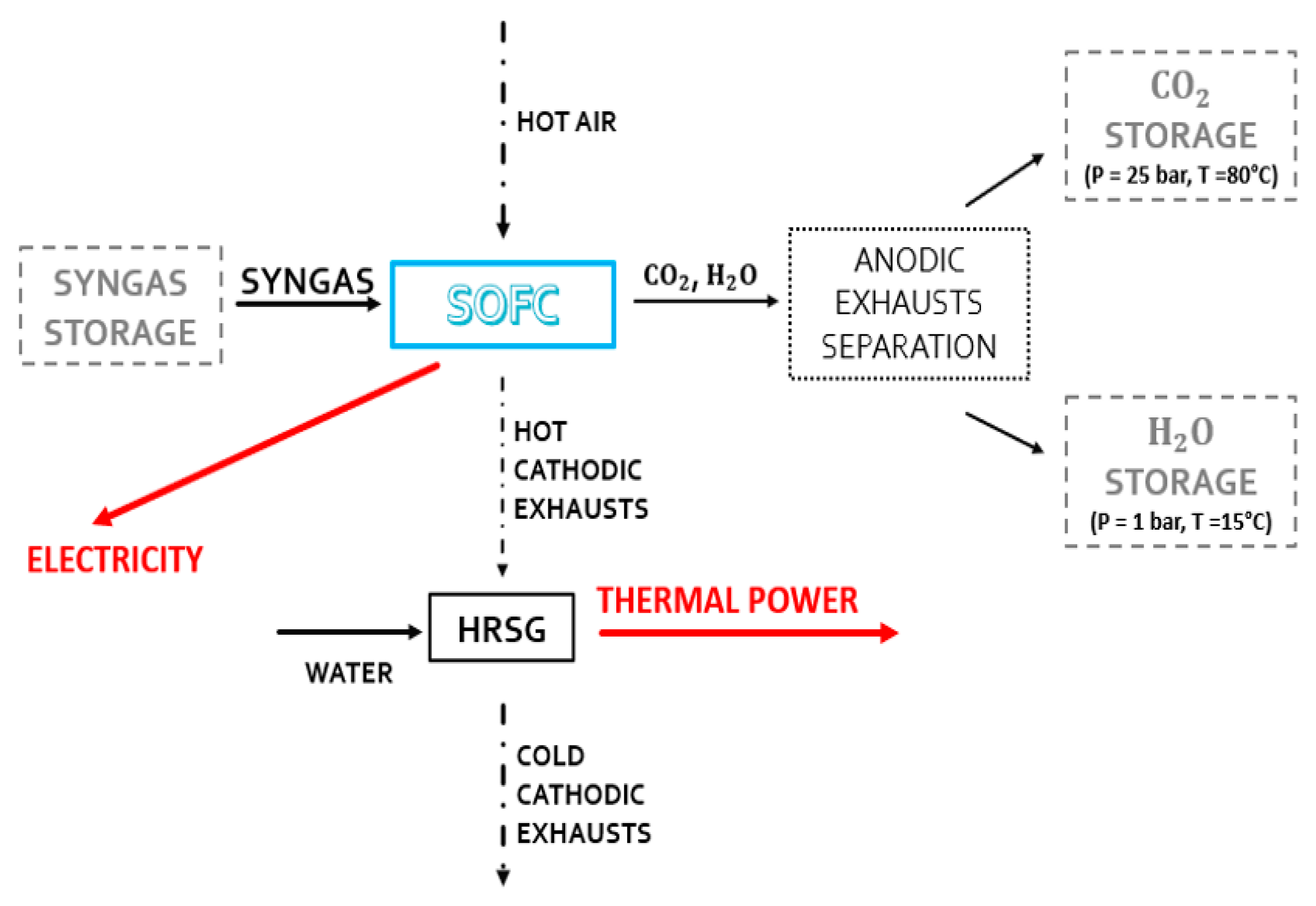
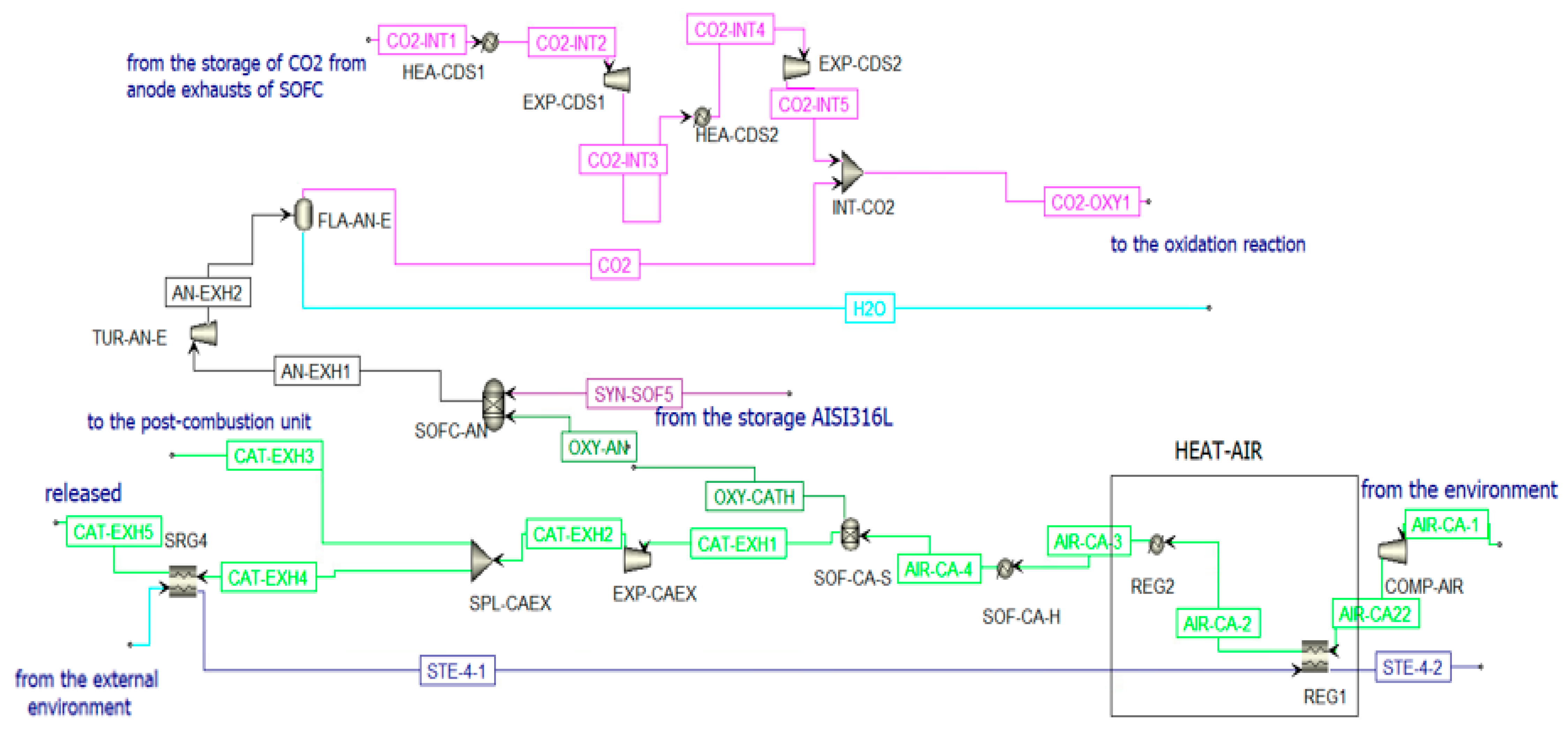
  • Fixed SOFC unit. The secondary unit is fed by the syngas produced in the CL reduction reactor. Electricity is generated in this unit;
  • DME synthesis and distillation unit integrated with biomethane reforming reactor fed by concentrated solar energy for CCU unit [52]. This is another secondary unit fed with syngas. The syngas is produced in the oxidation reactor of CL. DME, methanol, and syngas are produced from this unit;
  • Steam generation plant. There are five steam generators with heat recovery in the plant that use the hot flows of the system to generate steam. This steam is used to heat other cold process flows and to generate thermal energy to supply other consumers (e.g., a district heating network).
The chemical cycle can operate properly at sufficient irradiance to heat the reduction reactor at 900 °C, while at lower irradiance levels, the chemical cycle turns off. A comparison is made with a similar non-solar polygeneration system published in the literature [53]. An attempt to increase the system’s productivity by decoupling its operation from solar energy fluctuations is made. The results of the chemical cycle integrated into the system are compared with experimental [54] and modeling studies [41,55].
The proposed plant produces thermal energy, electricity, syngas, methanol, and dimethyl ether (DME), in two operating conditions:
(1)
Operation on a day with a clear sky and irradiance sufficient for the CL operation;
(2)
Operation on a day with low solar irradiance.
In the first operating condition (see Figure 3), all components of the plant can work properly. The reduction reactor of the CL is oversized compared to the SOFC. An excess of syngas is obtained from the reduction reactor. This gas mixture is stored and used during periods of low solar irradiation. This storage system is fundamental to couple the solar syngas with the correct operation of the SOFC system. This system is very sensitive to load variations and transients due to its high operating temperature.
The uniqueness of the SOFC system’s operation is provided in the second operating condition plant. This system is fed by properly stored syngas (see Figure 4). When solar energy is not present, the chemical cycle and consequently the synthesis of DME, the distillation unit, and the reforming reactor do not come into operation. Therefore, the anode fluxes of the SOFC system are stored for reuse when the CL system is operational.
These different operating conditions are defined by considering the seasonal average daily temperatures of the reduction reactor. The experimental data for the modeling analysis are taken from the dish facility placed at the Turin-Energy Center [56]. Looking at the seasonal daily average temperature of the dish system, it is found that the temperature is higher/equal to 900 °C (see Figure 5):
(1)
For 8 h and 30 min every day in the summer season;
(2)
For 7 h and 40 min every day in the spring season;
(3)
For 3 h and 40 min every day in the autumn season;
(4)
Never active in winter.
In summary, the chemical cycle can operate around 21% of the year. The SOFC system is designed to operate continuously.

2.1. Modeling and Plant Simulation in Aspen Plus

In this study, the simulation tool used is Aspen Plus® from AspenTech (v10, Bedford, MA, USA). In both plant schemes (Figure 3 and Figure 4), the plant is modeled mainly with built-in components and assumes chemical equilibrium in each component. The DME reactor is characterized by a kinetic approach. The main plant components are:
-
Turbines, valves, coolers, distributors, mixers, heaters, compressors, heat recovery steam generators, flash units, and cyclones;
-
RGIBBS reactor units are used to model the chemical looping oxidation and reduction reactors, the post-combustion unit, the SOFC anode, and the biomethane reforming reactor;
-
Separator (coupled with a heat exchanger) for the cathode of the SOFC;
-
RADFRAC columns used to model the DME distillation unit;
-
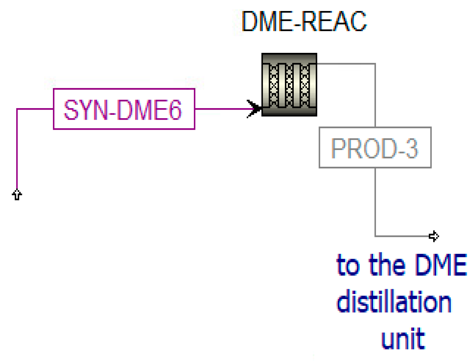
RPLUG reactor coupled to the kinetic model Langmuir–Hinshelwood–Hougen–Watson (LHHW) is used to simulate the DME synthesis reactor with a catalytic behavior. In this unit, it is used for the thermodynamic properties of the Soave–Redlich–Kwong (SRK) equation of state (EOS). A similar approach was followed by Graaf et al. [58], where the SRK equation of state was used to model the chemical equilibrium of the methanol and water gas shift (WGS) reaction. This model is applied to binary components [59].
In the model, the flows used are conventional (H2O, CO2, H2, CO, CH4, N2, O2, CH3OH, and CH3OCH3) and fixed flows (oxygen carriers of chemical looping, CeO2 and Ce2O3). The Barin equation is used for the evaluation of the fixed flow [60]. For conventional flows, the Peng–Robinson–Boston–Mathias (PR-BM) properties method is used. This approach is widely used in the literature for the treatment of hydrocarbons, such as refining in petrochemical processes [61,62]. Table 1 lists the main assumptions used.

2.2. Plant Operating Components in a High-Irradiance Clear Sky Day

2.2.1. Chemical Looping and Storage System

The constant-temperature and -pressure operating conditions for the CL process increase the efficiency by reducing losses associated with heat flows and high system pressures. Concerning the reduction reaction, the operating temperature and the amount of methane to be fed are chosen to consider the following three requirements (see Figure 6):
-
The temperature should be compatible with a solar system;
-
The complete reduction of the oxygen carrier to Ce2O3 must take place with a limited amount of biomethane;
-
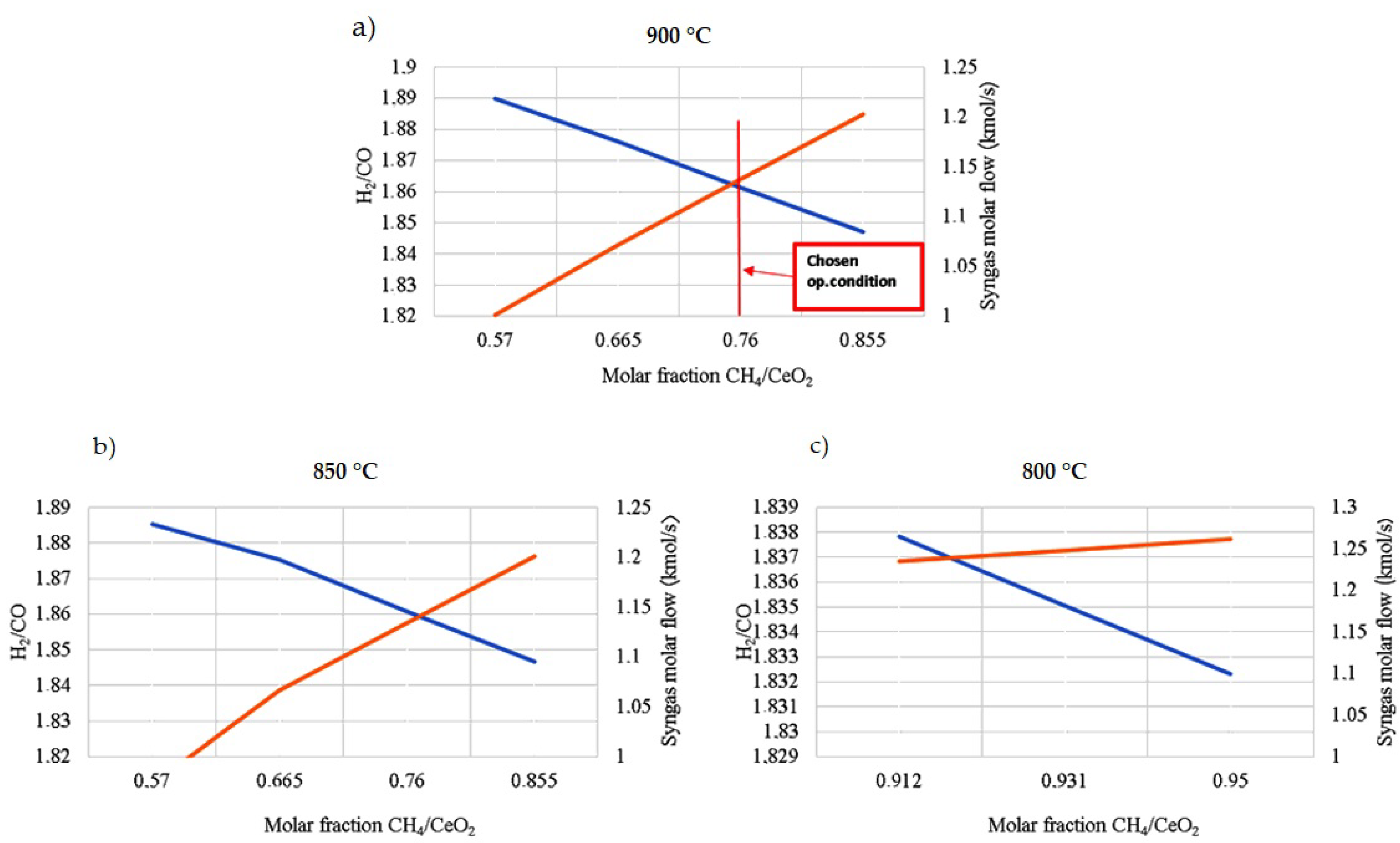
The desired syngas concentration has a molar ratio of H2/CO around 2. This molar ratio is more suitable to feed fuel cell systems. H2 diffuses quicker in the anode than CO and the diffusion overvoltage is reduced [63].
The flow mixture between the biomethane and CeO2 ratio varies directly with syngas production. Increasing the biomethane content increases the CO flow rate and, thus, decreases the H2/CO ratio.
The H2O/CO2 molar ratio is ≈1.13 for the oxidation reaction to obtain:
-
The complete re-oxidation of Ce2O3 to CeO2;
-
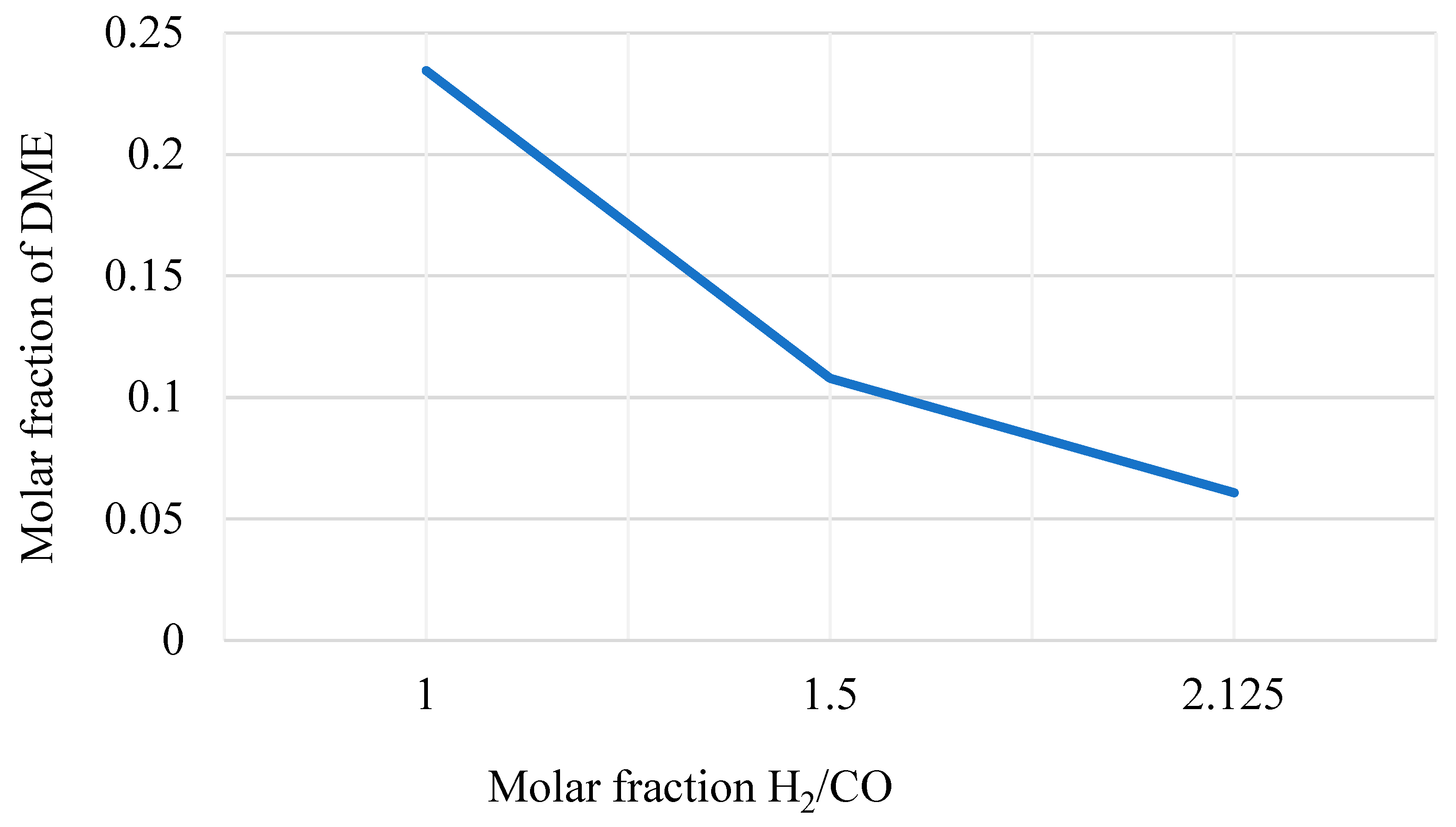
An H2/CO molar ratio around 1. This is an optimal value for the downstream DME production in the proper reactor (see Figure 7).
Figure 8 reports the chemical looping implemented in Aspen Plus.
The inlet streams of the reduction reactor (RED-CL) are constituted by biomethane (METH-1) and CeO2 (CER-OXY). Particle size is defined from the particle distribution reported in Supplementary Table S1 [64]. At the outlet of this reactor, the flow PROD-1 is separated in cyclone CYC-1. Two different streams are produced. The first stream (Ce2O3 (CER-RED)) is sent to the oxidation reactor, while the second stream is the syngas fraction (SYN-SOF1). This stream is compressed and cooled to be stored in the AISI316L tank [65]. This fraction is stored at 10 bar and 800 °C, following the mechanical and physical properties of AISI316L. However, in Aspen Plus, there is no model for the storage system simulation. Thus, downstream COMP-SYR and SRG1, there is a splitter (SPL-SYNS), which separates the flow entering the anode of the SOFC (SYN-SOF4) from the flow that should remain in the storage (SYN-S-ST), and a valve (VAL-SY) that reduces the pressure of the portion of syngas sent to the SOFC at 5 bar (SYN-SOF5). To sum up, for a continuous operation of the SOFC, the SYN-SOF1 mole flow is spread over the whole year and the molar flow stream SYN-SOF4 is obtained according to Equation (5).
n ˙ SYN - SOF 4   =   n ˙ SYN - SOF 1   ( kmol min )   operating   miuntes   of   the   CL operating   minutes   of   the   SOFC :   60   s min
Going back to the chemical looping unit, the oxidation reactor (OXY-CL) is fed by the reduced cerium oxide (CER-RED) and a mixture of H2O and CO2 coming from the anodic exhausts of the SOFC. The product of the oxidation reactor (PROD-2) goes to a cyclone CYC-2 to separate the solid fraction (CeO2) and the gaseous fraction (SYN-DME1). The solid flow is sent to the reduction reactor to close the cycle (CER-OX1) after a re-integration of the lost ceria (CER-REG2) for the nonunitary efficiency of the cyclones (Supplementary Table S2). The gaseous flow is sent to the DME production section of the plant.

2.2.2. Solid Oxide Fuel Cell (Secondary Device)

To produce electricity, a fuel cell is used to consider its higher efficiency and fuel flexibility compared to a thermal machine [66]. Particularly, an anode-supported planar Solid Oxide Fuel Cell is chosen for its advantages compared to the other fuel cells in the industry [67,68,69,70]. The SOFC is simulated in Aspen Plus for both situations when the CL is in the ON-state (Figure 9) and OFF-state (Supplementary Figure S1).
The operating conditions of the SOFC system are:
(1)
Temperature = 850 °C, which is compatible with syngas storage;
(2)
Pressure = 5 bar, to improve the cell’s performance [71].
The SOFC operating temperature could be lowered using new and advanced materials. It is selected as a condition suitable for the bloom energy generator [72].
As specified in Section 2.2.1, the syngas mole flow entering the anode of the SOFC is n ˙ SYN-SOF5; another inlet stream in the anode is given by the oxygen ions (OXY-AN). The molar flow rate of this stream is equal to the stoichiometric molar flow rate of the oxygen O2 needed to generate in the cathode an amount of ions O2− sufficient to oxidize the fuel. It is calculated according to the Faraday law (4):
  n ˙ oxy - an = C t o t Z O 2     F
where C t o t = current produced by the cell and Z O 2 = 4, so   n ˙ oxy-an = 148.42 mol s . This molar flow rate of oxygen is set equal to the molar flow rate of the stream OXY-CATH exiting from the component SOF-CA-S to simulate the conduction of the ions from the anode to the cathode in the electrolytic layer of the SOFC. The cathode is supplied by air that enters the plant at ambient conditions to then be compressed and heated to 5 bar and 600 °C. The molar flow rate of the air stream is calculated iteratively to be heated from 600 °C to 850 °C, absorbing the entire heat rejected by the SOFC [73]:   n ˙ AIR-CA-3 = 3.044 kmol s . Once the air stream (AIR-CA-3) enters the cathode, it first encounters a heater that simulates the heating of the air and then a separator in which the streams OXY-CATH and CATH-EXH1 are produced. The latter represents the cathodic exhausts. They are expanded and then split into two streams. One stream (CAT-EXH4) feeds an HRSG (SRG4) to produce steam before the external release (CAT-EXH5); the other stream (CAT-EXH3) feeds the post-combustion unit. Considering a cell voltage equal to around 0.8 V, the Solid Oxide Fuel Cell can produce an electric power equal to 45.82 MWe. Using the Bloom Energy Servers [72] with an electric power production of 200 kW, the number of necessary modules is 230.

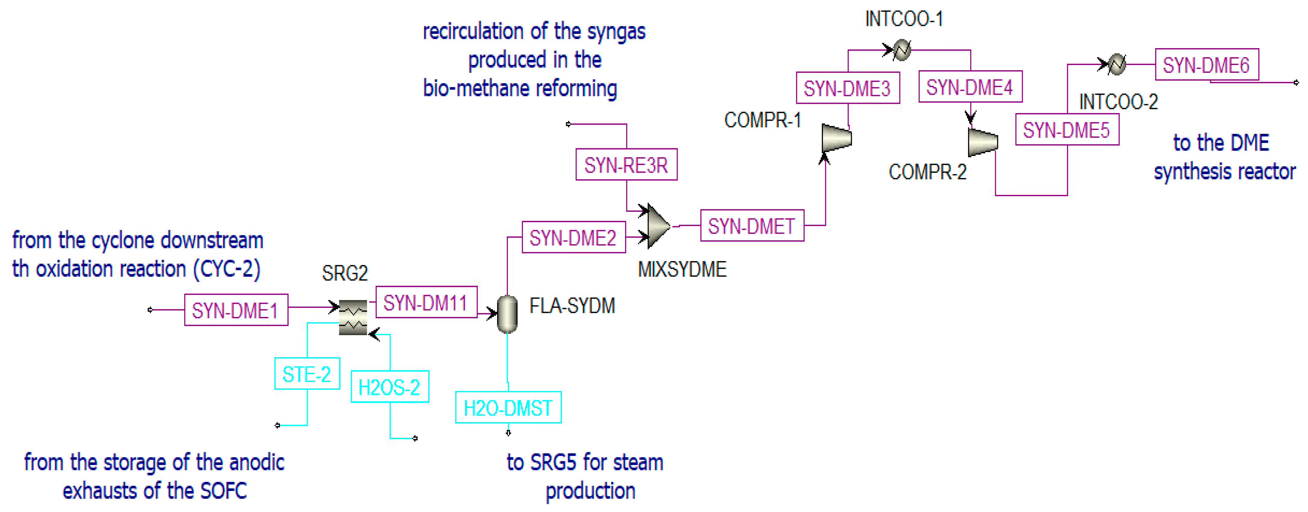
2.2.3. DME Production (Secondary Device)

DME Synthesis

The single-step pathway with a dual catalyst and the co-production of methanol and DME is chosen for the DME synthesis. This process is characterized by a significant increase in the total methanol yield compared to the two-step pathway with methanol and DME produced in two different reactors [74]. Three main reactions occur: syngas conversion to methanol (reaction (7)), water gas shift (reaction (8)), and methanol dehydration to DME (reaction (9)).
CO2 + 3H2 → CH3OH + H2O    ΔH0 = −49.2 kJ/mol
CO + H2O → CO2 + H2                ΔH0 = −41.2 kJ/mol
2CH3OH → CH3OCH3 + H2O   ΔH0 = −24.0 kJ/mol
The global reaction is:
3H2 + 3CO → CH3OCH3 + CO2    ΔH0 = −246.0 kJ/mol
According to the Le Châtelier principle [42], the global reaction is favored at high pressure and low temperature. The chosen catalytic reactor is a multi-tube fixed-bed reactor that is kept at a constant temperature of 250 °C and at 50 bar [75]. The bi-functional catalyst Cu/ZnO/Al2O3: γ-Al2O3 is selected considering a loading ratio of 1:2 from the literature. The syngas produced in the oxidation reactor of the chemical looping (SYN-DME2), before being sent to the DME synthesis reactor (see Figure 10), is:
  • Cooled in the heat recovery steam generator (SRG2), producing steam;
  • Separated from water (in FLA-SYDM);
  • Integrated with additional syngas (SYN-RE3R) produced in the biomethane reforming reactor and compressed to the operating pressure.
The DME reactor is simulated in Aspen plus (Figure 11) and solved with the SRK-EOS property method. The parameters for the modeling of this component are listed in Table 2 [53].
A Langmuir–Hinshelwood–Hougen–Watson (LHHW) kinetic model is implemented considering the three simultaneous reactions defined above ((7), (8), and (9)). The expressions of the rates for CO2 hydrogenation, WGS, and methanol dehydration are calculated according to Equations (11)–(13), respectively [74,76]. These reaction rates are expressed in kmol kg cat · s :
r C O 2 , h y d r o g e n a t i o n = k 1   ( p H 2 · p C O 2 )   [ 1 ( 1 k e q , 1 ) · p C H 3 O H · p H 2 O p C O 2 · p H 2 3   ]   ( 1 + k 2 · p H 2 O p H 2 + k 3 · p H 2 + k 4 · p H 2 O ) 3
r W G S = k 5 · p C O 2   [ 1 ( 1 k e q , 2 ) · p C O · p H 2 O p C O 2 · p H 2   ]   1 + k 2 · p H 2 O p H 2 + k 3 · p H 2 + k 4 · p H 2 O
r M e O H , d e h y d r a t i o n = k 6   K C H 3 O H 2   [ C C H 3 O H 2 C H 2 O · C D M E K e q , 3     ]   ( 1 + 2   k C H 3 O H · C C H 3 O H   + k H 2 O · C H 2 O ) 4
with:
-
p, gas partial pressure (Pa);
-
C, concentration (kmol/m3).
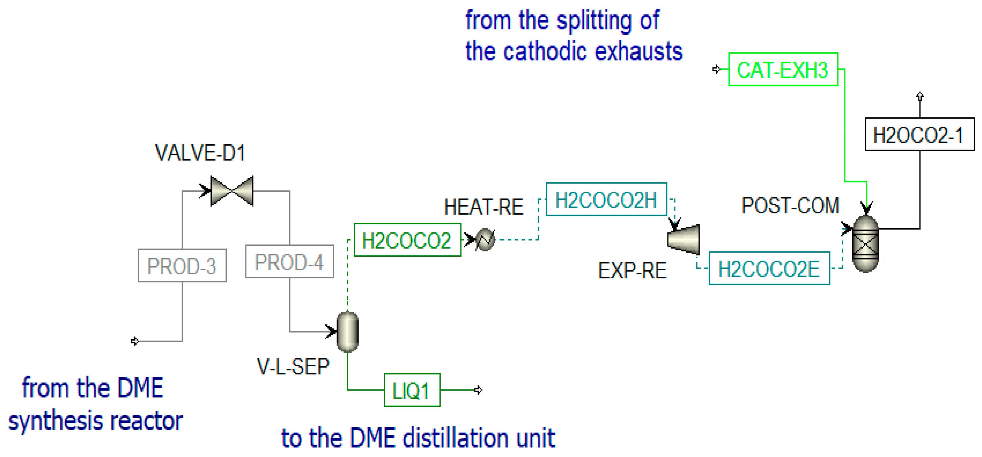
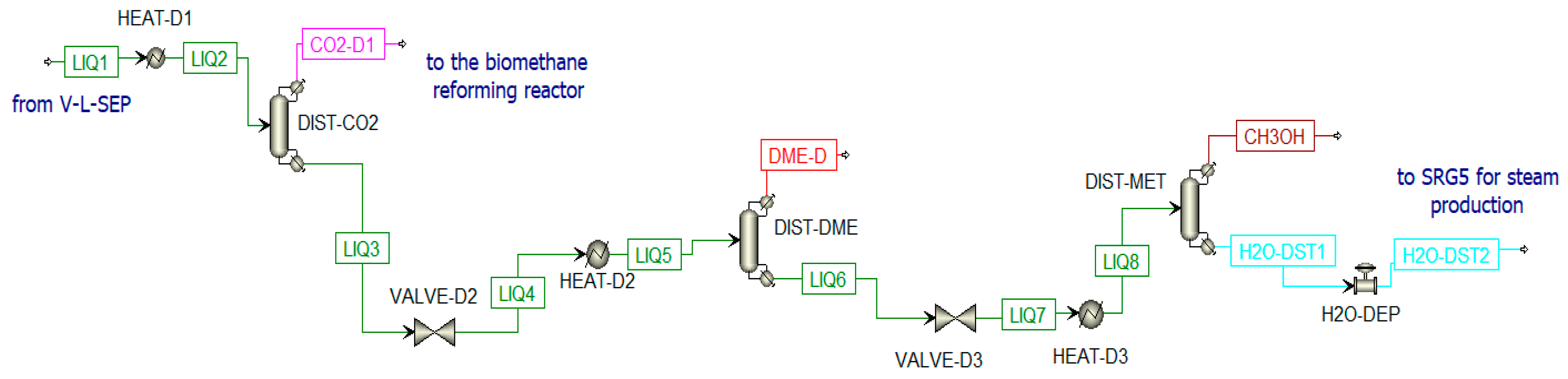
The parameters inserted in Equations (11)–(13) are taken from the literature [53].

Distillation Unit

The DME synthesized in the reactor (PROD-3) is characterized by a high amount of impurities; thus, a separation process and a distillation process are necessary to obtain pure DME. Before the distillation columns, there is a vapor–liquid separation unit (V-L-SEP) at −45 °C and 10 bar, as shown in Figure 12. The output streams of this component are incondensable gases (H2COCO2) and a liquid stream (LIQ1). The first stream (H2COCO2) is pre-heated to 400 °C and expanded. The resulting stream is sent to a post-combustion chamber (POST-COM) (see Figure 12) to produce H2OCO2-1, which is cooled in a heat recovery steam generator (SRG3) to be separated in a flash unit (SEP-RE) (see Figure 13). The obtained water at the bottom of the reactor is used to produce steam in counter-flow with the post-combustion exhausts in the previously mentioned SRG3, while the gaseous stream feeds the biomethane reforming reactor (METH-REF) after being mixed with other streams of CO2. These additional streams come from the portion of the anodic exhausts of the SOFC (CO2-RS-3) stored when the chemical looping is in OFF-state and not used in the oxidation reactor of the CL itself throughout the year. Another stream that enters the reforming reactor is biomethane (METH-2), taken from the pipeline. The aim of the biomethane reforming reactor (METH-REF) is to produce syngas following this reaction:
CH 4   +   CO 2 2 H 2   +   2 CO     Δ H 0   =   247.0   KJ / mol
This reaction is favored at low pressures and high temperatures. In the present study, it takes place at 800 °C and 1 bar. It can be fed by concentrated solar thermal energy in an additional receiver-reactor placed close to the reduction reactor of the CL. The syngas stream obtained from this reactor (SYN1) is cooled in the heat recovery steam generator (SRG5) and split (in SPL-SYN) to be partially recirculated to the DME synthesis reactor (SYN-RE3R) and partially sent to a syngas duct (SYN-DUCT). This last stream is an additional output of the overall system.
The second stream from V-L-SEP is a liquid stream mainly constituted of dissolved CO2, DME, and CH3OH (LIQ1). This stream is further treated in three different distillation columns (Figure 14):
  • Column for CO2 separation (DIST-CO2);
  • Column for DME production (DIST-DME);
  • Column for methanol separation from water (DIST-MET). The water stream (H2O-DST1) is mixed with other water streams for steam production in SRG5.
A valve and a heat exchanger are placed before each column to adjust the pressure to the optimal value and to have 50% of vapor in the column inlet stream [75]. The number of stages used in the distillation columns is estimated by increasing them until a certain change in composition is detected. In Table 3, the data inserted in the distillation columns are listed; while in Table 4 are listed the composition of thermodynamic properties of selected streams when the chemical looping is in ON-State.

Steam Production

In the analyzed plant, there are five heat recovery steam generators (SRG1, SRG2, SRG3, SRG4, and SRG5) with the primary purpose of cooling certain streams of the plant without wasting their high-temperature heat. In certain generators (SRG1 and SRG2), the water needs are completely satisfied through the recirculation of water produced in the system itself from different processes. In the others, the water is re-integrated from external sources. In Table 5, the steam streams produced in these HRSGs are listed.

Solar Tower and Heliostats

The reduction reactor of the chemical looping and the biomethane reforming reactor work simultaneously; they can be supplied by concentrated solar energy. As a result of the high temperatures and the overall thermal requirements (Wth,tot ~ 294 MWt), it is considered to use a solar tower system [77,78]. This system could be installed in Turin, with two receiver-reactors where the reduction and the oxidation take place. These receiver-reactors are similar to the receiver-reactor of the solar dish located on the Energy Center roof, both in terms of irradiance and temperature values. Furthermore, these data are available:
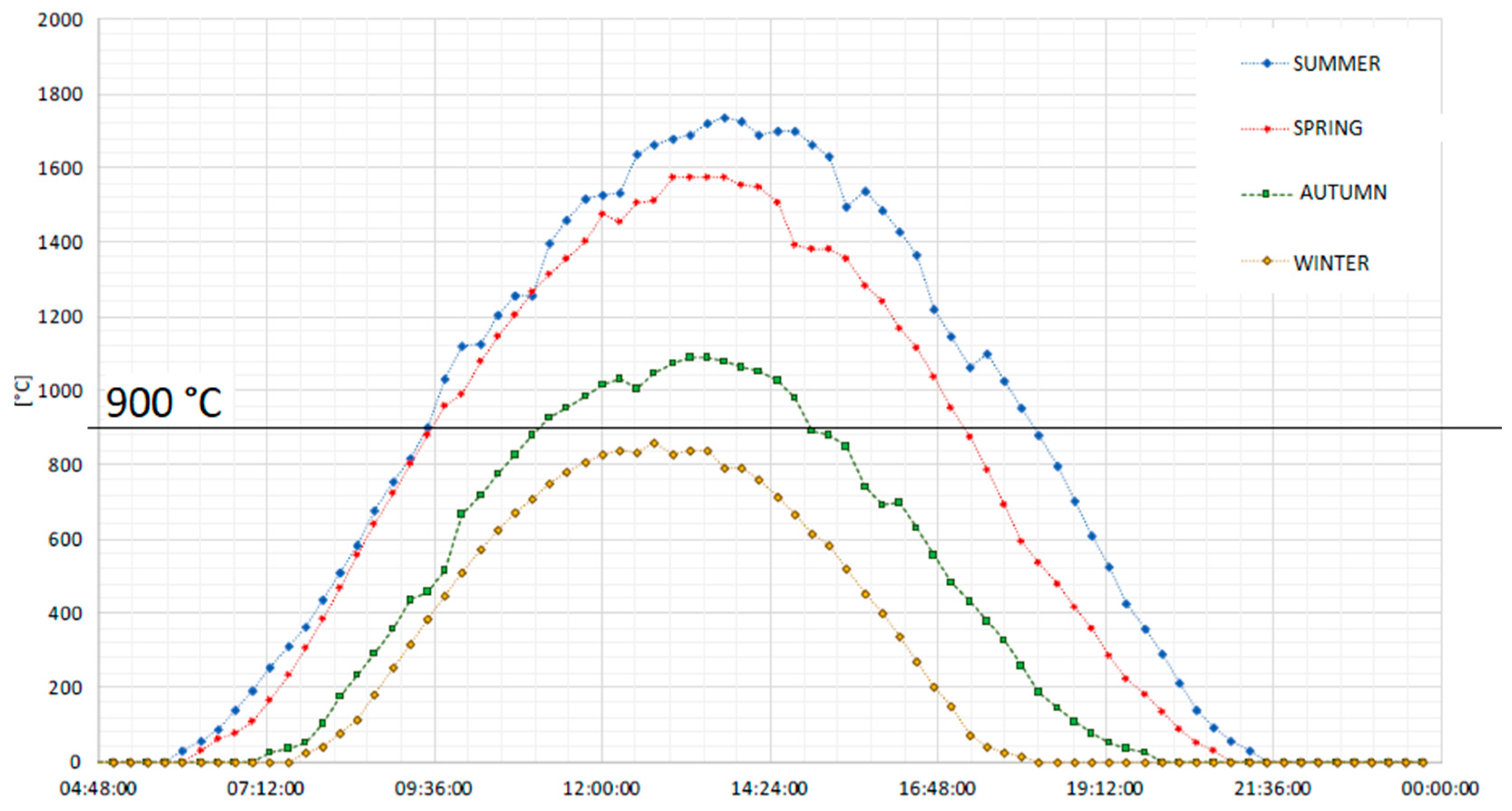
  • The experimental daily values of the direct normal irradiance in the neighborhood of the Energy Center, measured by the Politecnico meteorological station;
  • The experimental seasonal daily average temperatures of the receiver-reactor at the focus of the dish system installed on the Energy Center roof.
The yearly average direct normal irradiance (DNI) hitting the receiver-reactors and making the CL work properly is calculated to be around 828 W m 2 . Consequently, considering the optical efficiency of the solar field equal to 80%, its extension area should be around 44.27 hectares. To cover this area, 3170 heliostats with an aperture area of 140 m2 are necessary. The dimensions of the solar field are in the midpoint between those of the Khi Solar One system by Abengoa in the Northern Cape (South Africa) [79] and the Spanish Gemasolar system [80]. This aspect is highlighted because the electricity production of the polygeneration plant analyzed in this work is equal to the electricity production of the Spanish system (24.19 MWe vs. 20 MWe), underlining the possible competitiveness of this plant with other systems supplied by concentrated solar energy.

2.3. Plant Operating Components in the Absence of a Sufficient Irradiance

When the chemical looping cannot operate properly (Treceiver-reactor < 900 °C), the plant operates as shown in Figure 4.

2.4. Thermal Balance of the Plant

The thermal balance is fundamental for assessing system costs. In the present study, the plant is analyzed at steady-state conditions. The thermal needs of the different units of the plant are evaluated.

2.4.1. Thermal Analysis of the Chemical Looping

Solar energy satisfies the heat duty of the reduction reaction and the streams entering the reactor. On the other hand, the oxidation reaction is exothermic, and a fraction of heat can be used in other plant sections. In Supplementary Table S3, the heat duties of both these reactors are shown. The heating of the inlet flows of the oxidation reaction is executed exploiting a portion of the steam produced in SRG2 and SRG1 (Supplementary Figures S2–S4).

2.4.2. Thermal Analysis of the SOFC

In the SOFC scheme, a large amount of heat is required to bring air to 600 °C. This thermal requirement (in HEAT-AIR) can be satisfied as follows:
  • Air is heated in REG1 from 200 °C to 265 °C through the steam produced in SRG4;
  • After this pre-heating, the air stream can be further heated to 600 °C in two different ways:
    (a)
    If the CL unit operates, air can be heated in REG2;
    (b)
    If the CL does not operate, air can be heated through an electric heater. This drastically lowers the plant efficiency.

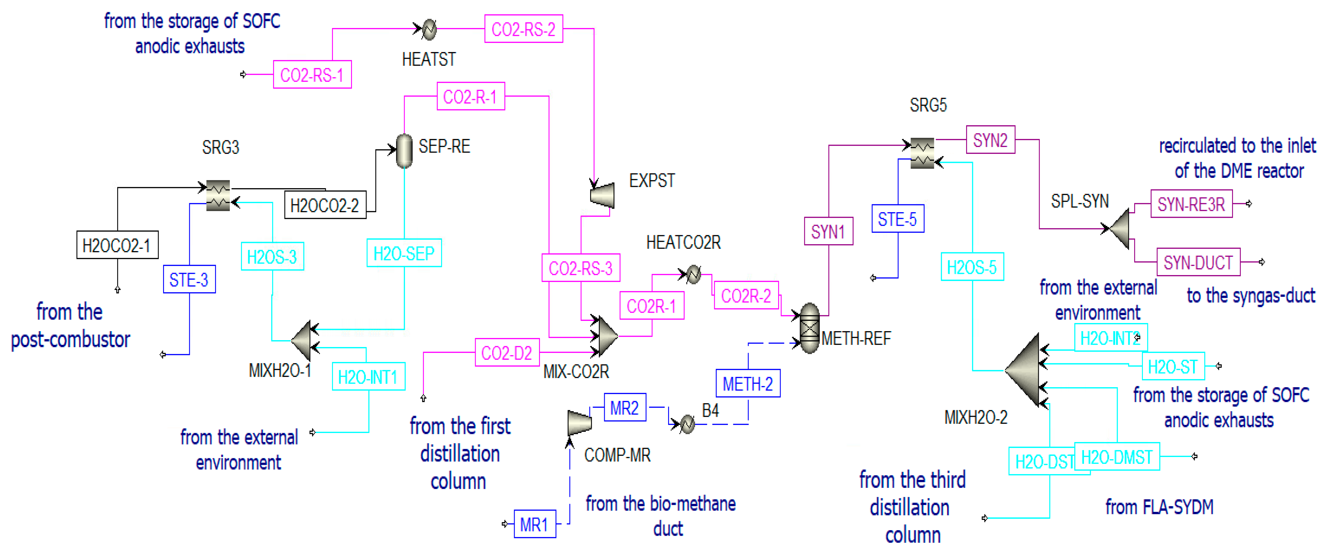
2.4.3. Thermal Analysis of the Reforming Unit

Different thermal flows are required for the biomethane reforming:
  • The vapor–liquid separation in V-L-SEP requires heat, and a steam portion produced in SRG5 is exploited (see Supplementary Figure S5);
  • The stream of CO2 coming from the storage of the anodic exhausts of the SOFC (CO2-RS-1) is heated in HEAT-ST through a steam portion produced in SRG5 (see Supplementary Figure S6);
  • Concentrated solar irradiance supplies the reforming reaction and heats the entering streams in the reactor. The thermal requirements of this section are listed in Supplementary Table S4.

2.4.4. Thermal Analysis of the Distillation Unit

Before the entry into the different distillation columns, the liquid is heated through a portion of steam produced in SRG2 (see Supplementary Figures S7 and S8). Additionally, the reboilers of the distillation columns [81] are supplied by the thermal load produced in the post-combustion reactor.

3. Discussion of the Plant Results

3.1. Plant Efficiencies

In this section, different plant efficiencies are evaluated considering the two operating conditions.

3.1.1. Electric Efficiency of the System

The net electric power produced from the plant is: WEL,NET,CL-ON = 6.17 MWe when the CL is in the ON-state and WEL,NET,CL-OFF = 28.96 MWe when the CL is in the OFF-state. The electric efficiency of the system is evaluated considering, respectively, the operation (15) or not (16) of the chemical looping:
η e l e c t r i c ,   C L   O N   =   W EL , NET , CL ON     Q R E D R E A C T O R ˙ +   m M E T H 1 ˙   ·   L H V M E T H A N E +   m M E T H 2 ˙   ·   L H V M E T H A N E + Q R E F O R M I N G ˙   = 0.6 %
  η e l e c t r i c ,   C L   O F F   =   W EL , NET , CL ON m S Y N ˙ SOFC · LHV SYN SOFC   = 26.41 %
The large difference between these two electric efficiencies is mainly related to the following relation W E L , T O T , C L O F F >> W EL , TOT , CL ON . When the CL is in the OFF-state, steam streams can be exploited, and the following components are in the OFF-state (COMP-SYR, COMPR-1, and COMPR-2).

3.1.2. Thermal Efficiency of the System

The waste steam and hot water streams produced in the five HRSGs could be mixed (see Supplementary Figures S9 and S10) and cooled to their initial temperature (15 °C) to produce thermal power. When the chemical looping is in the ON-state, Wth,tot,CL-ON = 111.97 MWt; otherwise, Wth,tot,CL-OFF = 35.82 MWt. The thermal efficiencies are, respectively, calculated as (17) and (18):
η t h e r m a l ,   C L O N   = W t h , t o t , C L O N   Q R E D R E A C T O R ˙ +   m M E T H 1 ˙   ·   L H V M E T H A N E +   m M E T H 2 ˙   ·   L H V M E T H A N E + Q R E F O R M I N G ˙   =   10.94 %
η t h e r m a l ,   C L O F F   = W t h , t o t , C L O F F   m S Y N S O F C ˙   ·   L H V S Y N S O F C =   32.67 %
This large difference is mainly related to the different fuels required by the system whether the CL is in the ON-state or OFF-state.

3.1.3. Solar/Biomethane-to-Fuel Efficiency of the System

The fuel production only occurs when the CL operates.
η S O L A R / B I O M E T H A N E T O F U E L ,   C L   O N   =       m D M E ˙   ·   L H V D M E +   m M E T H A N O L ˙   ·   L H V M E T H A N O L +   m S Y N D U C T ˙   ·   L H V S Y N D U C T     Q R E D R E A C T O R ˙ +   m M E T H 1 ˙   ·   L H V M E T H A N E +   m M E T H 2 ˙   ·   L H V M E T H A N E + Q R E F O R M I N G ˙   =   51 %
η S O L A R / B I O M E T H A N E T O F U E L ,   C L   O F F   =   0   m S Y N S O F C ˙   ·   L H V S Y N S O F C   =   0

3.1.4. Global Efficiencies of the System

The global efficiencies of the plant in its two different operating conditions are evaluated:
η g l o b a l ,   C L O N   = η e l e c t r i c ,   C L   O N     ×   η t h e r m a l ,   C L O N     ×   η S O L A R / B I O M E T H A N E T O F U E L ,   C L   O N   =   62.56 %
η g l o b a l ,   C L O F F   = η e l e c t r i c ,   C L   O F F     ×   η t h e r m a l ,   C L O F F     ×   η S O L A R / B I O M E T H A N E T O F U E L ,   C L   O F F   =   59.08 %
These results highlight the slight decrease in the global efficiency of the polygeneration plant at low solar irradiances.

3.2. Results Discussion and Comparison with Similar Plant

The results obtained from the polygenerative plant are examined and compared with a similar study, by Farooqui et al. [53]. The main differences are:
  • The unit chosen for electric power production by Farooqui et al. [53] is a gas turbine. The thermal energy generated by the oxyfuel combustion chamber is used to operate continuously the chemical looping cycle; therefore, there is no exploitation of solar energy;
  • The chemical looping executed by Farooqui et al. [53] is not isothermal, the two reactions take place at different temperatures (1312 °C and 900 °C), and it occurs at a higher operating pressure (2 bar).
A comparison between the average yearly outputs and inputs of the two plants is shown in Table 6.
As can be seen in Table 6, the main difference between the present study plant remains in the lower electric power and DME production. This is strictly linked to the solar intermittence, which makes the chemical looping not continuous throughout the year. Consequently, although the size of the two plants is comparable, the chemical looping of this work produces a lower average yearly amount of syngas to be used for electricity and DME production. However, it is important to emphasize the high amount of thermal power produced, methanol and syngas, the lower amount of bio-methane needed, and the higher average global efficiency. In addition, among its outputs, there is no carbon dioxide to be sequestrated, because the plant completely reuses the produced CO2 and executes the CCU.

3.3. Improvement in the Productivity of the Plant

In the attempt to increase the plant productivity, it is thought to decouple the chemical looping operation from the intermittence of solar energy. The reduction reactor of the chemical looping is supplied with the thermal load deriving from the SOFC system. It is necessary to lower the reduction reaction temperature at 800 °C (the SOFC operates at 850 °C) and, consequently, for the complete ceria reduction, it is necessary to increase the amount of biomethane, sent to the reduction reactor (as seen in Figure 6), to 0.95. In this plant, the syngas storage system is eliminated because the SOFC anode can be continuously supplied by the reduction reactor of the CL (continuous working). Thus, the SOFC stacks can produce WEL, SOFC = 243.48 MWe.
To fully eliminate the dependence of the polygeneration plant on the solar energy source, it is necessary to introduce a biomethane oxyfuel combustion unit.
The total biomethane requirement of this new unit is: m ˙ BIO-METH-THERMAL-TOT = 5.57 kg/s. This stream is sent to the oxyfuel combustion, according to reaction (23).
0.95CH4 + 0.05CO2 + 1.9O2 → CO2 + 1.9H2O
Thus, the total amount of O2 required to burn m ˙ BIO-METH-TOT is m ˙ O2-required = 19.48 kg/s. Biomethane oxyfuel combustion, as compared to direct fuel combustion [82,83], leads to combustion exhausts mainly constituted of H2O and CO2. However, to obtain pure O2, an Air Separation Unit is necessary. The specific energy expenditure of the Air Separation Unit, to produce an O2 stream with 98% purity, can be assumed equal to 925 kJ/kgO2 [84,85]. As a result, the total power expenditure of the ASU is 18.02 MWe. The new plant performances on a yearly basis are shown in the first column of Table 7. Comparing the new plant with the solar-aided plant and the plant of Farooqui et al. [53], the new system is the best from the point of view of electricity, DME, methanol, and syngas production. However, there is a much higher amount of biomethane consumption. Additionally, both Farooqui et al.’s plant [53] and the newly studied plant have the non-negligible issue of CO2 sequestration. The biomethane requirement of the new plant could be reduced by eliminating the reforming unit, even if the CO2 produced by the plant increases. This occurs because, beyond the CO2 production from the biomethane oxyfuel combustion, the distillation and the SOFC units contribute to CO2 production. The syngas lacks and CO2 production decreases the plant efficiency (even if the produced electric power is the highest). The performance of this plant is shown in the second column of Table 7.
From a pure planning point of view, there is no absolute optimum solution for the choice of the plant; this choice depends on the main goal:
  • If there is a need for a medium-sized plant (Wel,average requirement < 50 MW) to be installed in a location with a high availability of solar energy and space, the best choice would be the first polygeneration system analyzed with CS integration and no CO2 emissions;
  • If a large-sized plant is required (Wel,average requirement > 100 MW), with a high availability of biomethane, the best system is the new plant analyzed with the integration of the reforming unit, proving that adequate sequestration of the CO2 produced is achieved;
  • If a large-sized plant is required (Wel,average requirement > 100 MW), but no biomethane is available to feed the system, the optimal solution is the new system analyzed without the integration of the reforming unit. However, in the latter case, it is important to have an adequate and much larger storage system for the CO2 sequestering.
Considering the fuel production, the preferred system is the new system without solar energy integration but with the reforming unit; the other two systems are comparable.

4. Evaluation of the Chemical Looping Model Performance

This section focuses on the evaluation of the chemical looping performance comparing the results obtained from the CL model of the present study with other experimental [54] and modeling [41,55] literature studies. The present study simulates the CeO2/Ce2O3 chemical looping using two Gibbs reactors [41]. Thus, only the thermodynamics of the reactions is considered, and the kinetic limitations of the chemical reactions are neglected. The discrepancy between the thermodynamic simulation and the actual chemical reactions can be seen by comparing the model results of this work with the experimental study of the combined reduction of ceria and methane reforming in a particle transport reactor driven by solar energy [54]. However, these experiments [54] are executed at a temperature equal to 1302 °C (Table 8).
The main points of difference between thermodynamic simulation and real experiments are:
  • Absence of carbon deposits in the model. Thermodynamically, the phenomenon is verifiable at methane-to-ceria ratios above 1 and a temperature above 900 °C [41];
  • High methane conversion compared to the ideal case.
It follows that the evaluation of the chemical looping performance is made by considering other similar thermodynamic models, such as Bose et al. [41] and Warren et al. [55]. An agreement between the results is obtained, as shown in Supplementary Tables S5–S7. The operating conditions between Bose and the present study are similar, with an operating temperature of 900 °C and a ratio of 0.8 (CH4/CeO2). The molar concentration of carbon monoxide is similar, while the hydrogen fraction is slightly higher for Bose. This is due to a more uniform temperature distribution.

5. Conclusions

This study aims to evaluate the performance of a polygeneration plant to produce heat, electricity, DME, syngas, and methanol with the integration of a chemical looping CeO2/Ce2O3 driven by solar energy and coupled to the biomethane reforming system. Some advantages of this system can be listed below:
  • The plant using only renewable energy sources contributes to the industrial decarbonization;
  • A carbon capture and utilization unit is implemented. The system is very versatile and environmentally sustainable while still relying on fossil fuel energy production to a small extent. The SOFC unit could be replaced by an existing fossil-fuel power plant, whose effluent can be sent to the CL oxidation reactor and the reforming unit;
  • Production of innovative, green fuels that can help reduce the dependence on liquefied petroleum gases;
  • The use of the SOFC stack for electricity and heat generation. The efficiency of these systems is high, especially considering the electric share;
  • The production of syngas as an energy carrier to store and exploit the solar aleatoriness.
However, the coupling between the chemical looping and a solar energy system produces intermittence in the CL system. The absence of solar exploitation leads to a more complex system with greater production of electricity and green fuels. The following consequences arise:
  • Higher biomethane consumption;
  • CO2 production in the oxyfuel unit. This leads to problems with the CO2 produced.
Considering the decarbonization, the energy transition, and the reduction of greenhouse emissions as the main focus, the best system to install would be a polygeneration plant with the integration of a solar-powered chemical looping. Further studies could be conducted on this system, such as:
    • Evaluation of a kinetic model for chemical looping operation;
    • An economic analysis to assess the net present value and payback time of the investment;
    • An exergetic analysis to identify the components that can be improved in the complex process;
    • A more detailed assessment of the environmental impact and a discussion related to the material recovery of the various components.

Supplementary Materials

The following supporting information can be downloaded at: https://www.mdpi.com/article/10.3390/ma16010315/s1, Figure S1: SOFC scheme in Aspen Plus when the CL is in OFF-state; Figure S2: Thermal balance of HEA-CDS1 and HEA-CDS2 in Aspen Plus; Figure S3: Thermal balance of HEAT-CO2 in Aspen Plus; Figure S4: Thermal balance of HEAT-H2O in Aspen Plus; Figure S5: Thermal balance of HEAT-RE in Aspen Plus; Figure S6: Thermal balance of HEAT-ST in Aspen Plus; Figure S7: Thermal balance HEAT-D2 in Aspen Plus; Figure S8: Thermal balance of HEAT-D3 in Aspen Plus; Figure S9: Mixer of the steam and hot water streams of the plant and simulation of the cooling of the output stream (STE-TOT) to obtain useful thermal power (THE-REQ) when CL is in ON-state; Figure S10: Simulation of the thermal recovery from steam when CL is in OFF-state; Table S1: Particle size distribution of the ceria as a function of the frequency obtained from ELPI measurements [63]; Table S2: Cyclones’ characteristics in Aspen Plus [65]; Table S3: Thermal balance of the chemical looping; Table S4: Thermal balance of the reforming unit; Table S5: Comparison of results of the reduction reactor model of this paper with the results reported by Bose et al. [36] at the chosen operating conditions of the solar aided CL; Table S6: Comparison of the results of the reduction reactor model of this study with the results reported by Warren et al. [54] and by Bose et al. [36] at different operating conditions; Table S7: Comparison of the results of the model of this study with the results reported by Bose et al. [36] for the oxidation of ceria with H2O and CO2.

Author Contributions

Conceptualization, G.M., M.S. and D.P.; methodology, G.M. and D.P.; software, G.M. and D.F.; formal analysis, G.M., D.P. and D.F.; data curation, G.M. and D.P.; writing—original draft preparation, G.M. and D.P.; writing—review and editing, D.P.; supervision, M.S. and D.P. All authors have read and agreed to the published version of the manuscript.

Funding

This research received no external funding.

Data Availability Statement

Original data can be requested to the corresponding author.

Conflicts of Interest

The authors declare no conflict of interest.

Nomenclature

CCUCarbon Capture and Utilization
CLChemical Looping
CSConcentrated Solar energy
CSPConcentrated Solar Panels
DMEDimethyl-ether
DNIDirect Normal Irradiance
HRSGHeat Recovery Steam Generator
SOFCSolid Oxide Fuel Cell
LPGLiquefied Petroleum Gases
TSCsThermochemical Splitting Cycles

Units of measure

m ˙ mass flow rate, kg/s
n ˙ molar flow rate, mol/s
Δ T phase change temperature range, °C
llength, m
p pressure, bar
rreaction rate, kmol/(kgcat·s)
Ttemperature, °C
Welelectric power, We
Wththermal power, Wt
ρ density, kg/m3

References

  1. IPCC-Report—Global Warming of 1.5 °C. 2018. Available online: https://www.ipcc.ch/sr15/download/ (accessed on 15 August 2020).
  2. Stocker, M.; Qin, T.F.; Plattner, D. Climate Change 2013: The Physical Science Basis. Contribution of Working Group I to the Fifth Assessment Report of the Intergovernmental Panel on Climate Change; Cambridge University: Cambridge, UK; New York, NY, USA, 2013. [Google Scholar]
  3. European Commission. Strategic Energy Technology Plan. 2017. Available online: https://doi.org/10.2777/48982 (accessed on 23 October 2021).
  4. US EPA. Sources of Greenhouse Gas Emissions; United States Environmental Protection Agency: Washington, DC, USA, 2017. Available online: https://www.epa.gov/ghgemissions/sources-greenhouse-gas-emissions (accessed on 25 November 2021).
  5. Ampah, J.D.; Jin, C.; Fattah, I.M.R.; Appiah-Otoo, I.; Afrane, S.; Geng, Z.; Yusuf, A.A.; Li, T.; Mahlia, T.I.; Liu, H. Investigating the evolutionary trends and key enablers of hydrogen production technologies: A patent-life cycle and econometric analysis. Int. J. Hydrogen Energy 2022. Available online: https://doi.org/10.1016/j.ijhydene.2022.07.258 (accessed on 26 August 2022).
  6. Lu, Y.; Zhu, L.; Agrafiotis, C.; Vieten, J.; Roeb, M.; Sattler, C. Solar fuels production: Two-step thermochemical cycles with cerium-based oxides. Prog. Energy Combust. Sci. 2019, 75, 100785. [Google Scholar] [CrossRef]
  7. Detz, R.J.; Reek, J.N.H.; Zwaan, B.C.C.v.d. The future of solar fuels: When could they become competitive? Energy Environ. Sci. 2018, 11, 1653–1669. [Google Scholar] [CrossRef]
  8. Montà, E.; Santarelli, M.; Papurello, D. Synthetic-Gas Production through Chemical Looping Process with Concentrating Solar Dish: Temperature-Distribution Evaluation. Processes 2022, 10, 1698. [Google Scholar] [CrossRef]
  9. Qi, Y.; Huang, D. Energy and exergy analysis of supercritical/transcritical CO2 cycles for water injected hydrogen gas turbine. Energy 2022, 260, 124931. [Google Scholar] [CrossRef]
  10. Öberg, S.; Odenberger, M.; Johnsson, F. The value of flexible fuel mixing in hydrogen-fueled gas turbines—A techno-economic study. Int. J. Hydrogen Energy 2022, 47, 31684–31702. [Google Scholar] [CrossRef]
  11. Kalghatgi, G. Is it really the end of internal combustion engines and petroleum in transport? Appl. Energy 2018, 225, 965–974. [Google Scholar] [CrossRef]
  12. Lanzini, A.; Kreutz, T.G.; Martelli, E.; Santarelli, M. Energy and economic performance of novel integrated gasifier fuel cell (IGFC) cycles with carbon capture. Int. J. Greenh. Gas Control 2014, 26, 169–184. [Google Scholar] [CrossRef]
  13. Deka, T.J.; Osman, A.I.; Baruah, D.C.; Rooney, D.W. Methanol fuel production, utilization, and techno-economy: A review. Environ. Chem. Lett. 2022, 20, 3525–3554. [Google Scholar] [CrossRef]
  14. An, Y.; Lin, T.; Yu, F.; Yang, Y.; Zhong, L.; Wu, M.; Sun, Y. Advances in direct production of value-added chemicals via syngas conversion. Sci. China Chem. 2017, 60, 887–903. [Google Scholar] [CrossRef]
  15. Bernardi, A.; Graciano, J.E.A.; Chachuat, B. Production of chemicals from syngas: An enviro-economic model-based investigation. In Computer Aided Chemical Engineering; Kiss, A.A., Zondervan, E., Lakerveld, R., Özkan, L., Eds.; Elsevier: Amsterdam, The Netherlands, 2019; pp. 367–372. [Google Scholar] [CrossRef]
  16. Merkouri, L.-P.; Ahmet, H.; Reina, T.R.; Duyar, M.S. The direct synthesis of dimethyl ether (DME) from landfill gas: A techno-economic investigation. Fuel 2022, 319, 123741. [Google Scholar] [CrossRef]
  17. Semelsberger, T.A.; Borup, R.L.; Greene, H.L. Dimethyl ether (DME) as an alternative fuel. J. Power Sources 2006, 156, 497–511. [Google Scholar] [CrossRef]
  18. The Editors of Encyclopaedia Britannica, Methanol, Britannica. Available online: https://www.britannica.com/science/methanol (accessed on 26 November 2021).
  19. Meier, A.; Steinfeld, A. Solar Energy in Thermochemical Processing. In Solar Thermal Energy: S. alexopoulos; Kalogirou, S.A., Ed.; Springer: New York, NY, USA, 2022; pp. 315–347. [Google Scholar] [CrossRef]
  20. Smestad, G.P.; Steinfeld, A. Review: Photochemical and Thermochemical Production of Solar Fuels from H2O and CO2 Using Metal Oxide Catalysts. Ind. Eng. Chem. Res. 2012, 51, 11828–11840. [Google Scholar] [CrossRef]
  21. Wang, Y.; Liu, T.; Lei, L.; Chen, F. High temperature solid oxide H2O/CO2 co-electrolysis for syngas production. Fuel Process Technol. 2017, 161, 248–258. [Google Scholar] [CrossRef]
  22. Lei, L.; Zhang, J.; Yuan, Z.; Liu, J.; Ni, M.; Chen, F. Progress Report on Proton Conducting Solid Oxide Electrolysis Cells. Adv. Funct. Mater. 2019, 29, 1903805. [Google Scholar] [CrossRef]
  23. Kodama, T.; Bellan, S.; Gokon, N.; Cho, H.S. Particle reactors for solar thermochemical processes. Sol. Energy 2017, 156, 113–132. [Google Scholar] [CrossRef]
  24. Villafán-Vidales, H.; Arancibia-Bulnes, C.; Riveros-Rosas, D.; Romero-Paredes, H.; Estrada, C. An overview of the solar thermochemical processes for hydrogen and syngas production: Reactors, and facilities. Renew. Sustain. Energy Rev. 2017, 75, 894–908. [Google Scholar] [CrossRef]
  25. Yadav, D.; Banerjee, R. A review of solar thermochemical processes. Renew. Sustain. Energy Rev. 2016, 54, 497–532. [Google Scholar] [CrossRef]
  26. Steinfeld, A. Solar thermochemical production of hydrogen––A review. Sol. Energy 2005, 78, 603–615. [Google Scholar] [CrossRef]
  27. Jiang, Q.; Chen, Z.; Tong, J.; Yang, M.; Jiang, Z.; Li, C. Direct thermolysis of CO2 into CO and O2. Chem. Commun. 2017, 53, 1188–1191. [Google Scholar] [CrossRef]
  28. Boretti, A. Which thermochemical water-splitting cycle is more suitable for high-temperature concentrated solar energy? Int. J. Hydrogen Energy 2022, 47, 20462–20474. [Google Scholar] [CrossRef]
  29. Agrafiotis, C.; Roeb, M.; Sattler, C. A review on solar thermal syngas production via redox pair-based water/carbon dioxide splitting thermochemical cycles. Renew. Sustain. Energy Rev. 2015, 42, 254–285. [Google Scholar] [CrossRef]
  30. Pan, H.; Li, Y.; Zhu, L.; Lu, Y. Solar-driven H2O/CO2 conversion to fuels via two-step electro-thermochemical cycle in a solid oxide electrochemical cell. Energy Convers. Manag. 2022, 259, 115578. [Google Scholar] [CrossRef]
  31. Abanades, S. Redox Cycles, Active Materials, and Reactors Applied to Water and Carbon Dioxide Splitting for Solar Thermochemical Fuel Production: A Review. Energies 2022, 15, 7061. [Google Scholar] [CrossRef]
  32. Le Gal, A.; Vallès, M.; Julbe, A.; Abanades, S. Thermochemical Properties of High Entropy Oxides Used as Redox-Active Materials in Two-Step Solar Fuel Production Cycles. Catalysts 2022, 12, 1116. [Google Scholar] [CrossRef]
  33. Gorensek, M.B.; Corgnale, C.; Staser, J.A.; Weidner, J.W. Chapter 3—Thermochemical hydrogen processes. In Electrochemical Power Sources: Fundamentals, Systems, and Applications; Smolinka, T., Garche, J., Eds.; Elsevier: Amsterdam, The Netherlands, 2022; pp. 63–82. [Google Scholar] [CrossRef]
  34. Kodama, T.; Gokon, N. Thermochemical Cycles for High-Temperature Solar Hydrogen Production. Chem. Rev. 2007, 107, 4048–4077. [Google Scholar] [CrossRef] [PubMed]
  35. Carrillo, R.J.; Scheffe, J.R. Advances and trends in redox materials for solar thermochemical fuel production. Sol. Energy 2017, 156, 3–20. [Google Scholar] [CrossRef]
  36. Xiao, l.; Wu, S.-Y.; Li, Y.-R. Advances in solar hydrogen production via two-step water-splitting thermochemical cycles based on metal redox reactions. Renew. Energy 2012, 41, 1–12. [Google Scholar] [CrossRef]
  37. Calle, A.d.l.; Bayon, A. Annual performance of a thermochemical solar syngas production plant based on non-stoichiometric CeO2. Int. J. Hydrogen Energy 2019, 44, 1409–1424. [Google Scholar] [CrossRef]
  38. Abanades, S.; Flamant, G. Thermochemical hydrogen production from a two-step solar-driven water-splitting cycle based on cerium oxides. Sol. Energy 2006, 80, 1611–1623. [Google Scholar] [CrossRef]
  39. Chuayboon, S.; Abanades, S. Solar Carbo-Thermal and Methano-Thermal Reduction of MgO and ZnO for Metallic Powder and Syngas Production by Green Extractive Metallurgy. Processes 2022, 10, 154. [Google Scholar] [CrossRef]
  40. Farooqui, A.; Bose, A.; Boaro, M.; Llorca, J.; Santarelli, M. Assessment of integration of methane-reduced ceria chemical looping CO2/H2O splitting cycle to an oxy-fired power plant. Int. J. Hydrogen Energy 2020, 45, 6184–6206. [Google Scholar] [CrossRef]
  41. Bose, A.; Farooqui, A.; Ferrero, D.; Santarelli, M.; Llorca, J. Thermodynamic assessment of non-catalytic Ceria for syngas production by methane reduction and CO2 + H2O oxidation. Mater. Renew. Sustain. Energy 2019, 8, 5. [Google Scholar] [CrossRef] [Green Version]
  42. Treptow, R.S. Le Châtelier’s principle: A reexamination and method of graphic illustration. J. Chem. Educ. 1980, 57, 417. [Google Scholar] [CrossRef]
  43. Wang, Z.; Gong, Z.; Turap, Y.; Wang, Y.; Zhang, Z.; Wang, W. Renewable hydrogen production from biogas using iron-based chemical looping technology. Chem. Eng. J. 2022, 429, 132192. [Google Scholar] [CrossRef]
  44. Simakov, D.S.A.; Wright, M.M.; Ahmed, S.; Mokheimer, E.M.A.; Román-Leshkov, Y. Solar thermal catalytic reforming of natural gas: A review on chemistry, catalysis and system design. Catal. Sci. Technol. 2015, 5, 1991–2016. [Google Scholar] [CrossRef]
  45. Maitlo, G.; Ali, I.; Mangi, K.H.; Ali, S.; Maitlo, H.A.; Unar, I.N.; Pirzada, A.M. Thermochemical Conversion of Biomass for Syngas Production: Current Status and Future Trends. Sustainability 2022, 14, 2596. [Google Scholar] [CrossRef]
  46. Prussi, M.; Padella, M.; Conton, M.; Postma, E.D.; Lonza, L. Review of technologies for biomethane production and assessment of Eu transport share in 2030. J. Clean. Prod. 2019, 222, 565–572. [Google Scholar] [CrossRef]
  47. Adams, T.A.; Ghouse, J.H. Polygeneration of fuels and chemicals. Curr. Opin. Chem. Eng. 2015, 10, 87–93. [Google Scholar] [CrossRef]
  48. Jana, K.; Ray, A.; Majoumerd, M.M.; Assadi, M.; De, S. Polygeneration as a future sustainable energy solution—A comprehensive review. Appl. Energy 2017, 202, 88–111. [Google Scholar] [CrossRef]
  49. Kaniyal, A.A.; van Eyk, P.J.; Nathan, G.J.; Ashman, P.J.; Pincus, J.J. Polygeneration of Liquid Fuels and Electricity by the Atmospheric Pressure Hybrid Solar Gasification of Coal. Energy Fuels 2013, 27, 3538–3555. [Google Scholar] [CrossRef]
  50. Liu, R.; Liu, M.; Zhao, Y.; Ma, Y.; Yan, J. Thermodynamic study of a novel lignite poly-generation system driven by solar energy. Energy 2021, 214, 119075. [Google Scholar] [CrossRef]
  51. Bai, Z.; Liu, Q.; Lei, J.; Li, H.; Jin, H. A polygeneration system for the methanol production and the power generation with the solarâ—biomass thermal gasification. Energy Convers. Manag. 2015, 102, 190–201. [Google Scholar] [CrossRef]
  52. Chen, W.H. CO2 conversion for syngas production in methane catalytic partial oxidation. J. CO2 Utili. 2014, 5, 1–9. [Google Scholar] [CrossRef]
  53. Farooqui, A.; Tomaso, F.D.; Bose, A.; Ferrero, D.; Llorca, J.; Santarelli, M. Techno-economic and exergy analysis of polygeneration plant for power and DME production with the integration of chemical looping CO2/H2O splitting. Energy Convers. Manag. 2019, 186, 200–219. [Google Scholar] [CrossRef]
  54. Welte, M.; Warren, K.; Scheffe, J.R.; Steinfeld, A. Combined Ceria Reduction and Methane Reforming in a Solar-Driven Particle-Transport Reactor. Ind. Eng. Chem. Res. 2017, 56, 10300–10308. [Google Scholar] [CrossRef] [PubMed]
  55. Warren, K.J.; Reim, J.; Randhir, K.; Greek, B.; Carrillo, R.; Hahn, D.W.; Scheffe, J.R. Theoretical and Experimental Investigation of Solar Methane Reforming through the Nonstoichiometric Ceria Redox Cycle. Energy Technol. 2017, 5, 2138–2149. [Google Scholar] [CrossRef]
  56. co2circlelab—RES. Available online: https://co2circlelab.eu/technologies/res (accessed on 21 November 2022).
  57. Papurello, D.; Bertino, D.; Santarelli, M. CFD Performance Analysis of a Dish-Stirling System for Microgeneration. Processes 2021, 9, 1142. [Google Scholar] [CrossRef]
  58. Graaf, G.H.; Winkelman, J.G.M. Chemical Equilibria in Methanol Synthesis Including the Water–Gas Shift Reaction: A Critical Reassessment. Ind. Eng. Chem. Res. 2016, 55, 5854–5864. [Google Scholar] [CrossRef]
  59. Shim, H.M.; Lee, S.J.; Yoo, Y.D.; Yun, Y.S.; Kim, H.T. Simulation of DME synthesis from coal syngas by kinetics model. Korean J. Chem. Eng. 2009, 26, 641–648. [Google Scholar] [CrossRef]
  60. Li, F.; Zeng, L.; Velazquez-Vargas, L.G.; Yoscovits, Z.; Fan, L.-S. Syngas chemical looping gasification process: Bench-scale studies and reactor simulations. AIChE J. 2010, 56, 2186–2199. [Google Scholar] [CrossRef]
  61. Peng, D.-Y.; Robinson, D.B. A New Two-Constant Equation of State. Ind. Eng. Chem. Fundam. 1976, 15, 59–64. [Google Scholar] [CrossRef]
  62. Eltony, A.M.; Park, H.G.; Wang, S.X.; Kong, J.; Chuang, I.L. Motional Heating in a Graphene-Coated Ion Trap. Nano Lett. 2014, 14, 5712–5716. [Google Scholar] [CrossRef]
  63. Andersson, M.; Yuan, J.; Sundén, B. SOFC modeling considering electrochemical reactions at the active three phase boundaries. Int. J. Heat Mass Transf. 2012, 55, 773–788. [Google Scholar] [CrossRef] [Green Version]
  64. Issa, M.; Petit, C.; Brillard, A.; Brilhac, J.-F. Oxidation of carbon by CeO2: Effect of the contact between carbon and catalyst particles. Fuel 2008, 87, 740–750. [Google Scholar] [CrossRef]
  65. Stainless Steel Type 316/316L, Rolled Metal Products|Stainless, Aluminum & Specialty Alloys. Available online: https://rolledmetalproducts.com/stainless-steel-type-316316l/ (accessed on 21 November 2022).
  66. Montazerinejad, H.; Eicker, U. Recent development of heat and power generation using renewable fuels: A comprehensive review. Renew. Sustain. Energy Rev. 2022, 165, 112578. [Google Scholar] [CrossRef]
  67. Mekhilef, S.; Saidur, R.; Safari, A. Comparative study of different fuel cell technologies. Renew. Sustain. Energy Rev. 2012, 16, 981–989. [Google Scholar] [CrossRef]
  68. Comparison of Fuel Cell Technologies. Available online: https://www.energy.gov/eere/fuelcells/comparison-fuel-cell-technologies (accessed on 21 November 2022).
  69. Somano, V.; Ferrero, D.; Santarelli, M.; Papurello, D. CFD model for tubular SOFC directly fed by biomass. Int. J. Hydrogen Energy 2021, 46, 17421–17434. [Google Scholar] [CrossRef]
  70. Papurello, D.; Silvestri, S.; Modena, S. Biogas trace compounds impact on high-temperature fuel cells short stack performance. Int. J. Hydrogen Energy 2021, 46, 8792–8801. [Google Scholar] [CrossRef]
  71. Patcharavorachot, Y.; Chatrattanawet, N.; Saebea, D.; Arpornwichanop, A. Performance assessment of a 10 kW pressurized solid oxide fuel cell integrated with glycerol supercritical water reforming. Int. J. Energy Res. 2022, 46, 13613–13626. [Google Scholar] [CrossRef]
  72. Bloom Energy Server. Available online: https://www.bloomenergy.com/resource/bloom-energy-server-es5-300kw/ (accessed on 21 November 2022).
  73. Yu, F.; Han, T.; Wang, Z.; Xie, Y.; Wu, Y.; Jin, Y.; Yang, N.; Xiao, J.; Kawi, S. Recent progress in direct carbon solid oxide fuel cell: Advanced anode catalysts, diversified carbon fuels, and heat management. Int. J. Hydrogen Energy 2021, 46, 4283–4300. [Google Scholar] [CrossRef]
  74. Ng, K.L.; Chadwick, D.; Toseland, B.A. Kinetics and modelling of dimethyl ether synthesis from synthesis gas. Chem. Eng. Sci. 1999, 54, 3587–3592. [Google Scholar] [CrossRef]
  75. Pozzo, M.; Lanzini, A.; Santarelli, M. Enhanced biomass-to-liquid (BTL) conversion process through high temperature co-electrolysis in a solid oxide electrolysis cell (SOEC). Fuel 2015, 145, 39–49. [Google Scholar] [CrossRef]
  76. Zaidi, A.A.; Naseer, M.N.; Ratlamwala, T.A.H. Energy Analysis of Methanol Synthesis via Reverse Water-Gas Shift Reactor. In Methanol: A Sustainable Transport Fuel for SI Engines; Agarwal, A.K., Valera, H., Pexa, M., Čedík, J., Eds.; Springer: Singapore, 2021; pp. 85–100. [Google Scholar] [CrossRef]
  77. Hoffschmidt, B.; Alexopoulos, S.; Göttsche, J.; Sauerborn, M.; Kaufhold, O. 3.06-High Concentration Solar Collectors. In Comprehensive Renewable Energy; Sayigh, A., Ed.; Elsevier: Oxford, UK, 2012; pp. 165–209. [Google Scholar] [CrossRef]
  78. Louis, S.; Francesco, S.; Adio, M.; Enzo, M.; Alfredo, F.; Massimo, F.; Thomas, C. Opportunità di applicazione delle tecnologie solari termodinamiche in Italia. Available online: https://www.pubblicazioni.enea.it/le-pubblicazioni-enea/edizioni-enea/anno-2016/opportunita-di-applicazione-delle-tecnologie-solari-termodinamiche-in-italia.html (accessed on 21 November 2022).
  79. Khi Solar One|Concentrating Solar Power Projects|NREL. Available online: https://solarpaces.nrel.gov/project/khi-solar-one (accessed on 21 November 2022).
  80. Burgaleta, J.I.; Arias, S.; Ramirez, D. Gemasolar, the First Tower Thermosolar Commercial Plant with Molten Salt Storage. Solarpaces 2011, 69, 20–23. Available online: https://www.researchgate.net/publication/264855919_Gemasolar_the_first_tower_thermosolar_commercial_plant_with_molten_salt_storage (accessed on 30 August 2022).
  81. Serth, R.W. 10—Reboilers. 2007. Available online: https://www.sciencedirect.com/science/article/pii/B9780123735881500139?via%3Dihub (accessed on 21 November 2022).
  82. Wang, Z. 1.23 Energy and Air Pollution. In Comprehensive Energy Systems; Dincer, I., Ed.; Elsevier: Oxford, UK, 2018; pp. 909–949. [Google Scholar] [CrossRef]
  83. Liu, C.Y.; Chen, G.; Sipöcz, N.; Assadi, M.; Bai, X.S. Characteristics of oxy-fuel combustion in gas turbines. Appl. Energy 2012, 89, 387–394. [Google Scholar] [CrossRef]
  84. Rogalev, A.; Rogalev, N.; Kindra, V.; Komarov, I.; Zlyvko, O. Research and Development of the Oxy-Fuel Combustion Power Cycles with CO2 Recirculation. Energies 2021, 14, 2927. [Google Scholar] [CrossRef]
  85. Koohestanian, E.; Shahraki, F. Review on principles, recent progress, and future challenges for oxy-fuel combustion CO2 capture using compression and purification unit. J. Environ. Chem. Eng. 2021, 9, 105777. [Google Scholar] [CrossRef]
Figure 1. Generic scheme of a thermochemical splitting cycle fed by concentrated solar energy.
Materials 16 00315 g001
Figure 2. Schematic representation of the ceria chemical looping coupled with biomethane reforming.
Materials 16 00315 g002
Figure 3. Prime mover and secondary devices of the polygeneration plant during a high-irradiance clear sky day.
Materials 16 00315 g003
Figure 4. Active components when the system does not receive adequate solar radiation.
Materials 16 00315 g004
Figure 5. Average temperature profile along the year in the solar concentrated dish placed in Turin [57].
Materials 16 00315 g005
Figure 6. Operating conditions of the reduction reactor, syngas production (orange line), and H2/CO molar ratio (blue line) varying the operating temperatures and the CH4/CeO2 molar ratio. (a) The chosen operating conditions are 900 °C and a CH4/CeO2 molar ratio equal to 0.76 to satisfy all three requirements of this reactor; (b) at 850 °C; (c) at 800 °C. CeO2 reduction is complete only with CH4/CeO2 molar ratios higher than 0.912, with a much higher expenditure of biomethane if compared with the other two cases.
Materials 16 00315 g006
Figure 7. DME yield in the DME synthesis reactor varying the H2/CO molar ratio of the inlet streams.
Materials 16 00315 g007
Figure 8. Chemical looping scheme in Aspen Plus.
Materials 16 00315 g008
Figure 9. SOFC scheme in Aspen Plus when the CL is in ON state.
Materials 16 00315 g009
Figure 10. Pre-treatment of the syngas sent to the DME reactor in Aspen Plus.
Materials 16 00315 g010
Figure 11. Simulation of the DME reactor in Aspen Plus.
Materials 16 00315 g011
Figure 12. Post-combustion unit in Aspen Plus.
Materials 16 00315 g012
Figure 13. Treatment of H2OCO2-1 and reforming unit in Aspen Plus.
Materials 16 00315 g013
Figure 14. Distillation unit in Aspen Plus.
Materials 16 00315 g014
Table 1. Main assumptions and hypotheses adopted in the process simulation.
Biomethane95% CH4, 5% CO2
Oxidation and reduction reactorsModel: RGIBBS, no heat losses
Compressors, pumps, and turbines η i s , c o m p = 0.9   η m e c h , c o m p = 0.98
η i s ,   t u r = 0.9   η m e c h , t u r = 0.98 η i s , p u m p   = 0.9
η d r i v e r , p u m p   = 0.9
SOFCSeparator and heat exchanger for the SOFC cathode Model: RGibbs for the SOFC anode
Methane reformingModel: RGibbs, no heat losses
Oxygen carrierCeO2, Ce2O3, a temperature drop of 20 °C from OXY-CL to RED-CL
DME reactorOperation T = 250 °C, p = 50 bar, Model: RPLUG multi-tube reactor
Distillation unitReboiler type: Kettle, Model: RADFRAC
DIST-CO2DIST-DMEDIST-MET
p = 10 barp = 9 barp = 2 bar
Table 2. Parameters of the DME reactor.
N° TubesDiameter (m)Bed VoidageDensity Cu/ZnO/Al2O3 (kg/m3)Density
γ-Al2O3 (kg/m3)
ρaverage (kg/m3)Temperature (°C)Pressure (bar)Length (m)
55000.020.451200147013802505015
Table 3. Distillation columns’ operation parameters.
Pressure
(bar)
TREB (°C)QREB (MW)TCOND (°C)QCOND
(MW)
Number of StagesFeed-in StagePurity of the Product
DIST-CO21049.641.1−40.58−1.52510-
DIST-DME9140.732.745.18−1.7302498%
DIST-MET2113.63182.89−0.8241899%
Table 4. Composition and thermodynamic properties of selected streams when the CL is in ON-STATE. The output material streams of the plant are highlighted.
StreamP
(bar)
T
(°C)
Mole Flow (kmol/s)Molar Fraction
Ce2O3 CeO2CH4 H2OCO2CO H2N2CH3OHDME
CER-OXY19000.590100000000
CER-RED1.199000.271000000000
SYN-SOF11.199001.140.0300.11000.300.56000
CO2-OXY219000.190000.010.790.070.13000
H2O-OXY219000.1800.0700.93000000
SYN-DME11.189000.4200.1300.090.060.340.38000
SYN-DME6502501.180000.040.060.460.430.0100
PROD-3502500.58000.010.010.420.110.160.020.040.23
CO2R-215000.71000.060.010.770.050.070.0400
METH-217000.42000.9500.0500000
SYN-DUCT1301.15000.010.030.040.480.44000
DME-D9450.1300000.010000.010.98
CH3OH2830.020000000010
Table 5. Cold sides of the HRSGs.
HRSGWater Requirements
Mole   Flows   ( k m o l m i n ) Outlet Temperature (°C) Additional   Water   from   the   External   Environment   ( kmol min )
SRG122.161326.50
SRG213.58546.50
SRG34.32381.43.5
SRG441.55475.2 when CL does not work41.5
463.9 when CL works
SRG540.40748.235
Total additional water requirement ( kmol min ) 80.1
Table 6. Comparison between the yearly average outputs of the polygeneration plant of this paper and Farooqui et al.’s study [53].
Farooqui et al. [53]Present Study
Biomethane feed (kton/year)220.7102.3
Wel,net,average (MWe)102.924.2
Wth,average (MWt)051.8
m ˙ DME (kton/year)67.840.8
m ˙ MeOH (ton/year)946.14686.4
Captured CO2 to be sequestrated (kton/year)271.80
Syngas (kton/year)0129.9
η t o t , a v e (%)50.259.8
Table 7. Performances of the new non-solar plants on yearly basis.
Farooqui et al. [53]New Plant without CSNew Plant without CS and Reforming
Biomethane feed (kton/year)220.75729.5425.2
W solar   field , ave (MWt) 00
Wel,net,average (Mwe)102.9119.7144.4
Wth,average (MWt)000
m ˙ DME (kton/year)67.8189.382.7
MeOH (ton/year)946.0841510.89703.6
Captured CO2 to be sequestrated (kton/year)271.84444.7797.6
Syngas (kton/year)0739.00
η t o t , a v e (%)50.2166.135.6
Table 8. Comparison between the results of the reduction reactor model of this paper and the experimental data in the literature [54].
Reduction Reaction Set-Up
Temperature (°C)1302
n C e O 2 ˙ . ( mmol min ) 44.2
n C H 4 , 0 ˙   ( mmol min ) 9
Products composition at the steady-state
ComponentPresent studyWelte, Warren, and Scheffe [54]
n H 2 ˙   ( mmol min ) 10.8514
n C O ˙   ( mmol min ) 7.496
n C O 2 ˙   ( mmol min ) 1.510.24
n H 2 O ˙   ( mmol min ) 6.250.75
n C H 4 ˙   ( mmol min ) 01.4
n C ˙   ( mmol min ) 01.2
Methane conversion
x C H 4 = 1 − n C H 4 ˙ n C H 4 , 0 ˙ 10.85
Disclaimer/Publisher’s Note: The statements, opinions and data contained in all publications are solely those of the individual author(s) and contributor(s) and not of MDPI and/or the editor(s). MDPI and/or the editor(s) disclaim responsibility for any injury to people or property resulting from any ideas, methods, instructions or products referred to in the content.

