
Competition between Sliding and Peeling of Graphene Nanoribbons under Horizontal Drag


Abstract
:1. Introduction
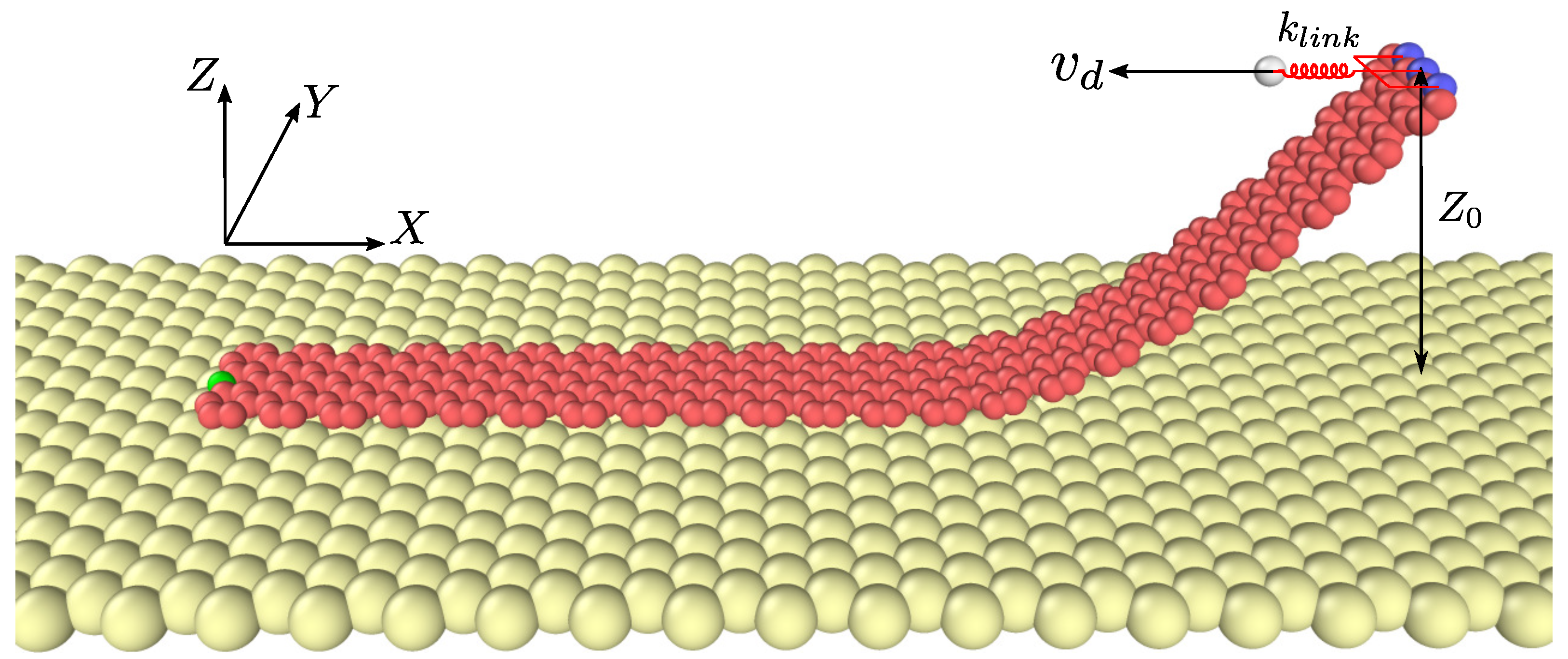
2. Model and Method
3. Results and Discussion
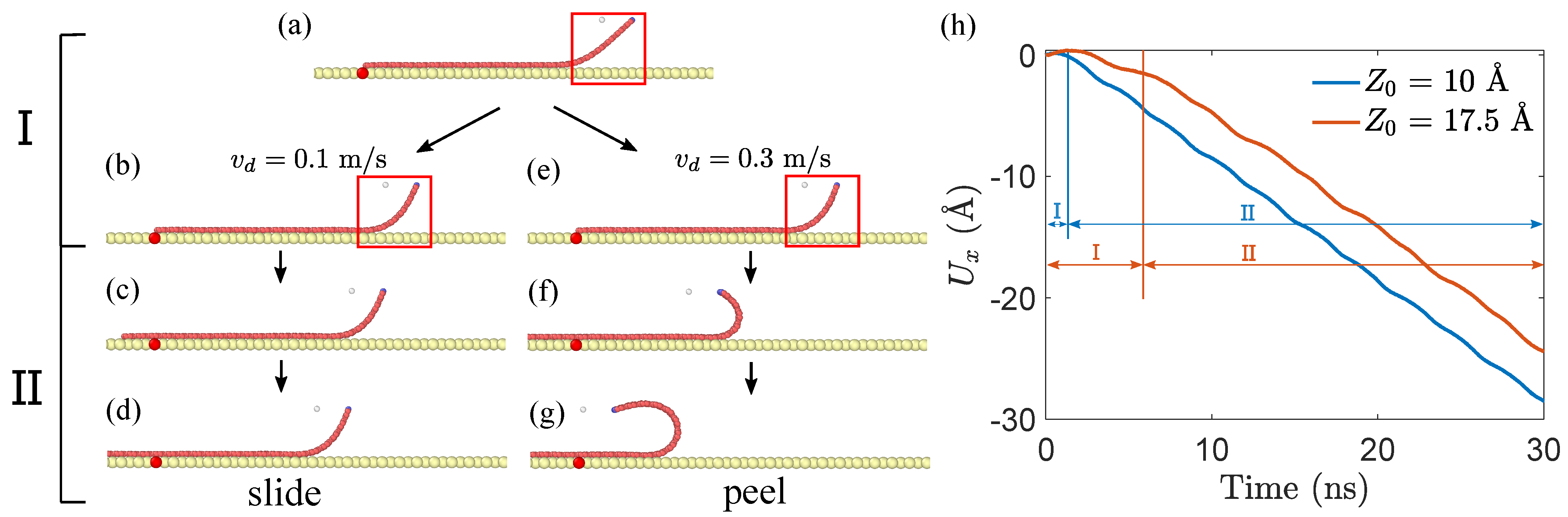
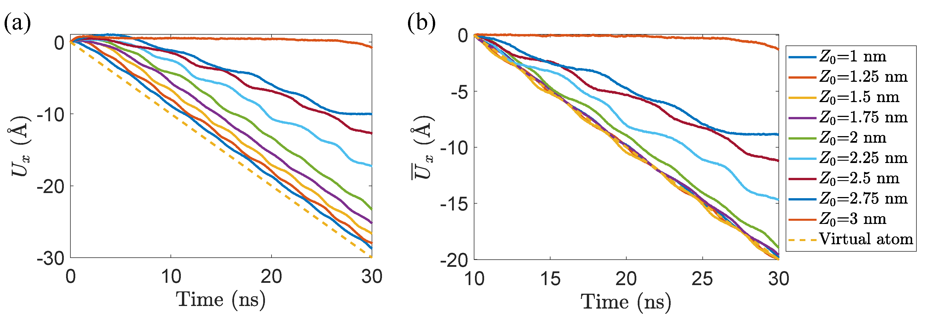
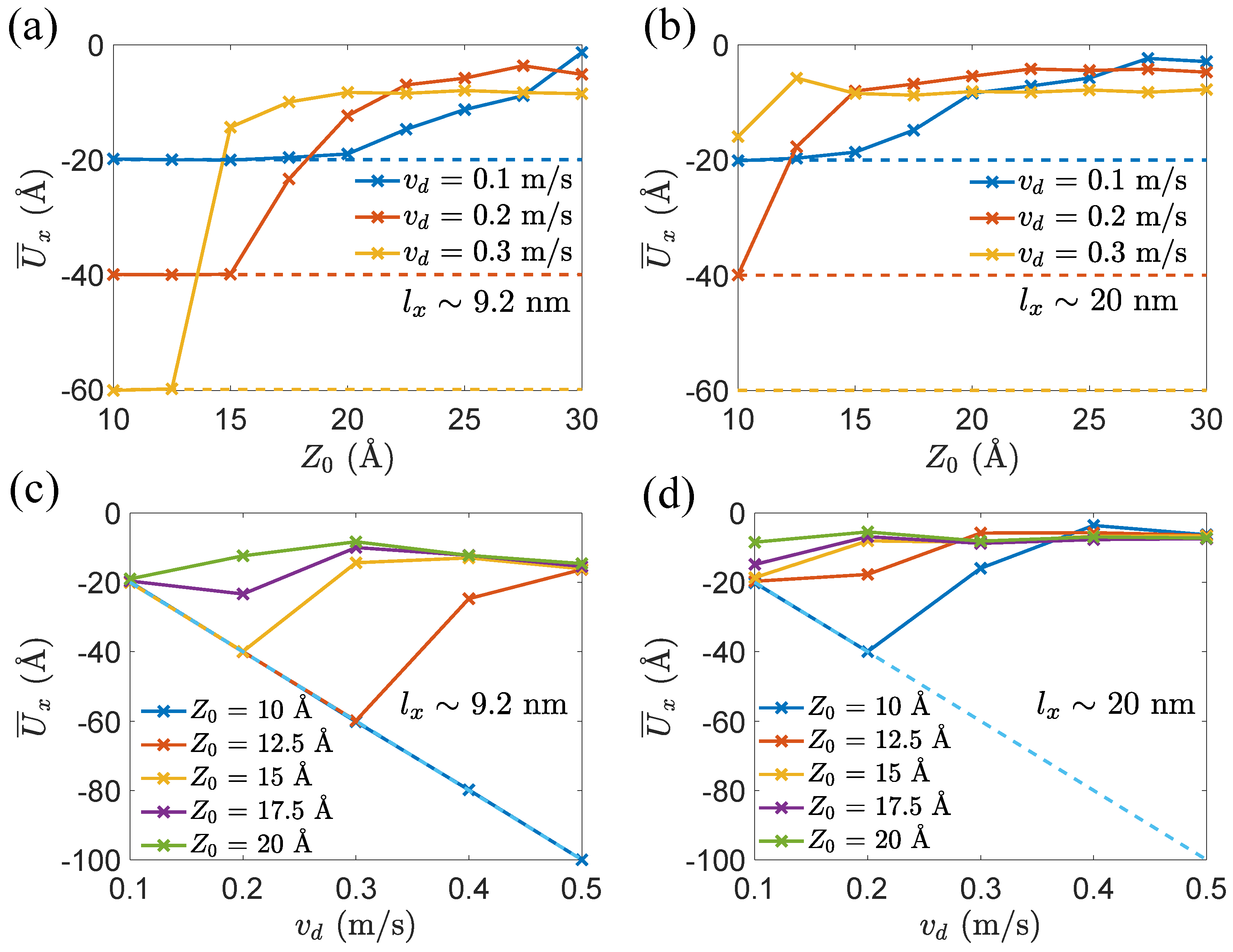
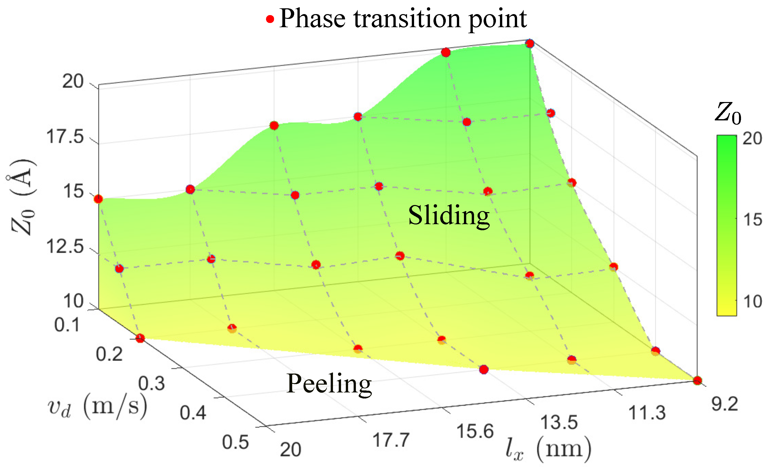
3.1. Competition between Peeling and Sliding Behaviors under Horizontal Drag
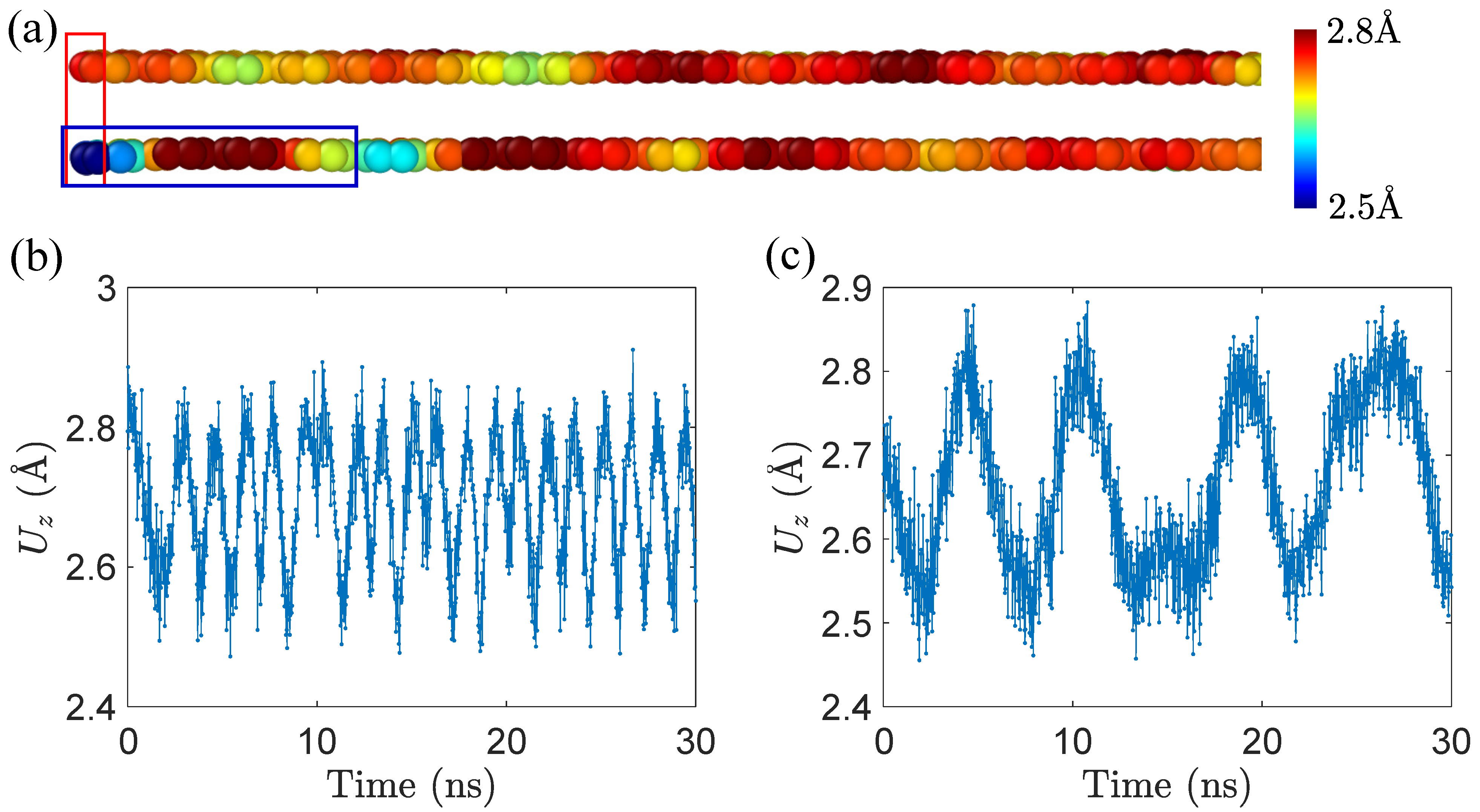
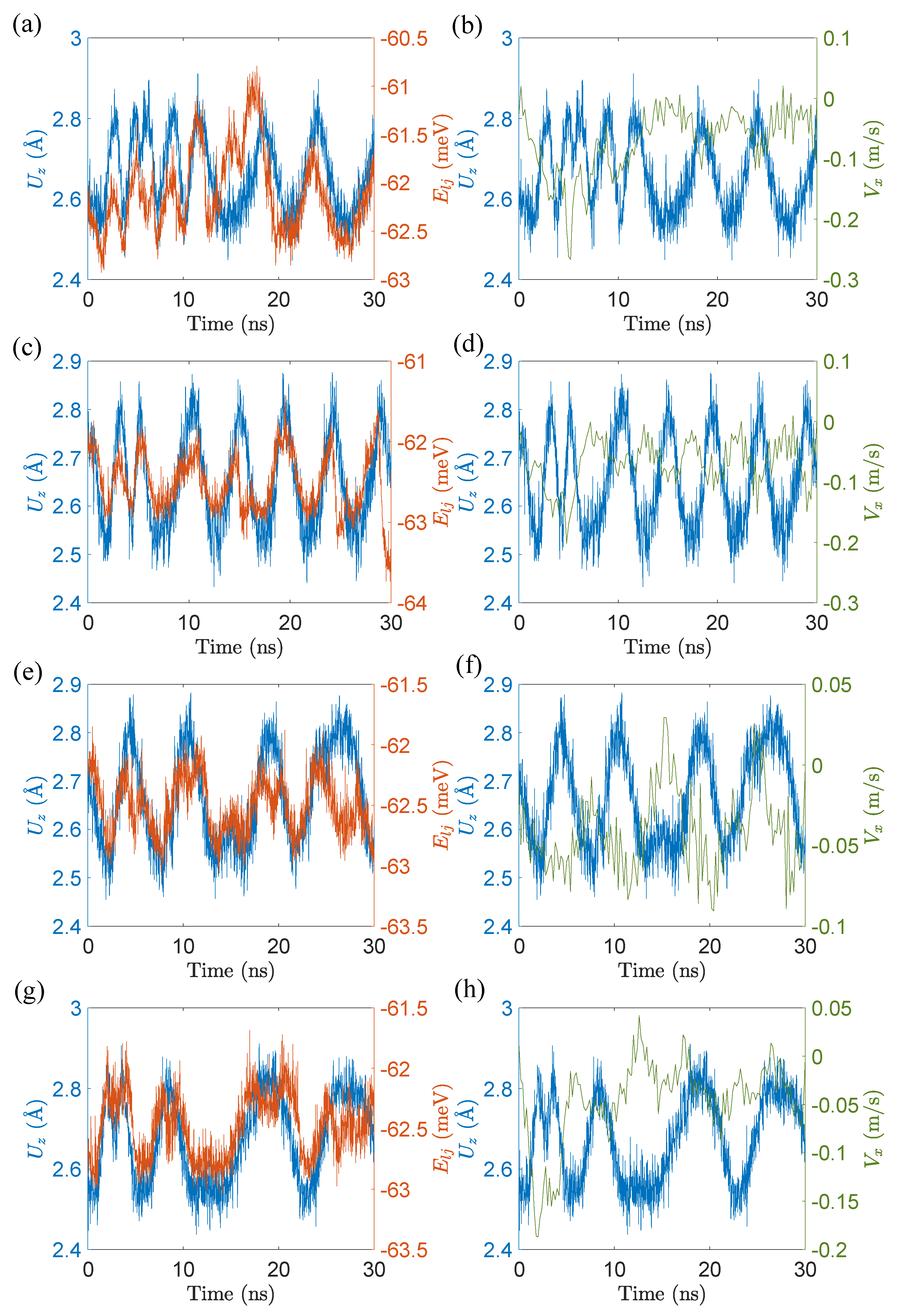
3.2. The Origination of Peeling Response
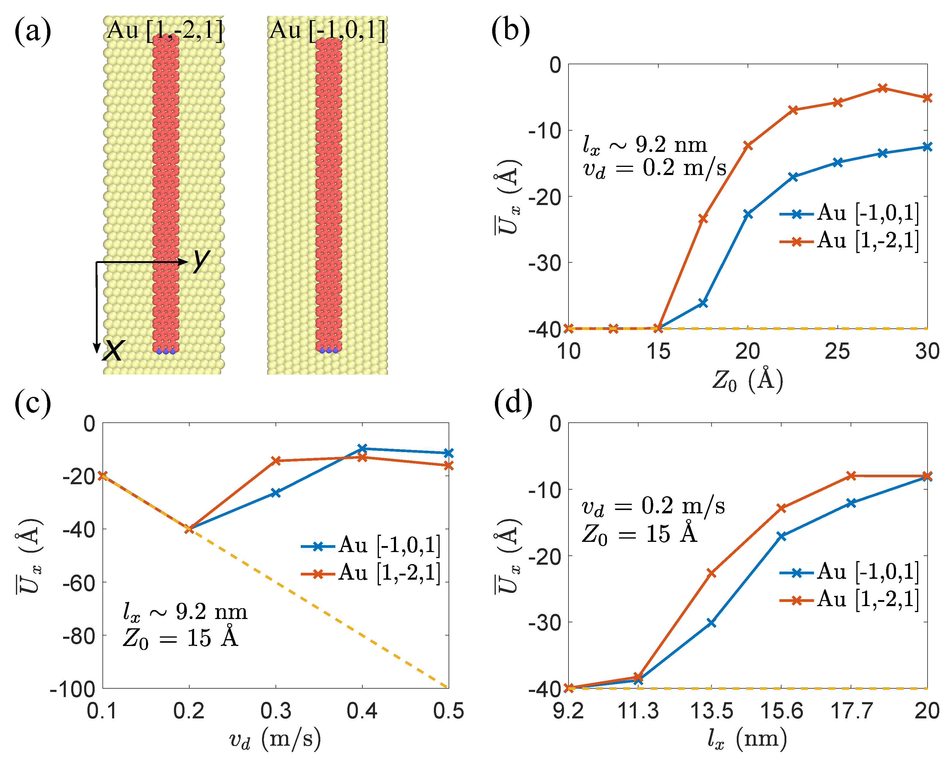
3.3. The Influence of Orientation
4. Conclusions
Supplementary Materials
Author Contributions
Funding
Institutional Review Board Statement
Informed Consent Statement
Data Availability Statement
Conflicts of Interest
Abbreviations
| GNR | Graphene nanoribbon |
| AFM | Atomic force microscope |
| hBN | Hexagonal boron nitride |
| REBO | Reactive empirical bond order |
References
- Zhao, H.; Min, K.; Aluru, N.R. Size and chirality dependent elastic properties of graphene nanoribbons under uniaxial tension. Nano Lett. 2009, 9, 3012–3015. [Google Scholar] [CrossRef] [PubMed]
- Apell, S.P.; Hanson, G.; Hägglund, C. High optical absorption in graphene. arXiv 2012, arXiv:1201.3071. [Google Scholar]
- Novoselov, K.S.; Jiang, Z.; Zhang, Y.; Morozov, S.; Stormer, H.L.; Zeitler, U.; Maan, J.; Boebinger, G.; Kim, P.; Geim, A.K. Room-temperature quantum hall effect in graphene. Science 2007, 315, 1379. [Google Scholar] [CrossRef] [PubMed] [Green Version]
- Geim, A.K.; Novoselov, K.S. The rise of graphene. Nat. Mater. 2007, 6, 183–191. [Google Scholar] [CrossRef]
- Lee, C.; Wei, X.; Kysar, J.W.; Hone, J. Measurement of the elastic properties and intrinsic strength of monolayer graphene. Science 2008, 321, 385–388. [Google Scholar] [CrossRef]
- Celis, A.; Nair, M.N.; Taleb-Ibrahimi, A.; Conrad, E.; Berger, C.; Heer, W.D.; Tejeda, A. Graphene nanoribbons: Fabrication, properties and devices. J. Phys. D Appl. Phys. 2016, 49, 143001. [Google Scholar] [CrossRef]
- Wei, D.; Liu, Y.; Zhang, H.; Huang, L.; Wu, B.; Chen, J.; Yu, G. Scalable synthesis of few-layer graphene ribbons with controlled morphologies by a template method and their applications in nanoelectromechanical switches. J. Am. Chem. Soc. 2009, 131, 11147–11154. [Google Scholar] [CrossRef]
- Sazonova, V.; Yaish, Y.; Üstünel, H.; Roundy, D.; Arias, T.A.; McEuen, P.L. A tunable carbon nanotube electromechanical oscillator. Nature 2004, 431, 284–287. [Google Scholar] [CrossRef] [Green Version]
- Min, S.K.; Kim, W.Y.; Cho, Y.; Kim, K.S. Fast DNA sequencing with a graphene-based nanochannel device. Nat. Nanotechnol. 2011, 6, 162–165. [Google Scholar] [CrossRef]
- Lin, J.; Peng, Z.; Xiang, C.; Ruan, G.; Yan, Z.; Natelson, D.; Tour, J.M. Graphene nanoribbon and nanostructured SnO2 composite anodes for lithium ion batteries. ACS Nano 2013, 7, 6001–6006. [Google Scholar] [CrossRef]
- Kawai, S.; Benassi, A.; Gnecco, E.; Söde, H.; Pawlak, R.; Feng, X.; Müllen, K.; Passerone, D.; Pignedoli, C.A.; Ruffieux, P.; et al. Superlubricity of graphene nanoribbons on gold surfaces. Science 2016, 351, 957–961. [Google Scholar] [CrossRef] [Green Version]
- Gigli, L.; Kawai, S.; Guerra, R.; Manini, N.; Pawlak, R.; Feng, X.; Müllen, K.; Ruffieux, P.; Fasel, R.; Tosatti, E.; et al. Detachment dynamics of graphene nanoribbons on gold. ACS Nano 2018, 13, 689–697. [Google Scholar] [CrossRef] [PubMed]
- Chang, J.S.; Kim, S.; Sung, H.-J.; Yeon, J.; Chang, K.J.; Li, X.; Kim, S. Graphene nanoribbons with atomically sharp edges produced by AFM induced self-folding. Small 2018, 14, 1803386. [Google Scholar] [CrossRef] [PubMed]
- Ouyang, W.; Mandelli, D.; Urbakh, M.; Hod, O. Nanoserpents: Graphene nanoribbon motion on two-dimensional hexagonal materials. Nano Lett. 2018, 18, 6009–6016. [Google Scholar] [CrossRef] [PubMed] [Green Version]
- Savin, A.; Korznikova, E.; Dmitriev, S. Twistons in graphene nanoribbons on a substrate. Phys. Rev. B 2020, 102, 245432. [Google Scholar] [CrossRef]
- Xue, Z.; Chen, G.; Wang, C.; Huang, R. Peeling and sliding of graphene nanoribbons with periodic van der Waals interactions. J. Mech. Phys. Solids 2022, 158, 104698. [Google Scholar] [CrossRef]
- Hu, G.; Zheng, C.; Ni, J.; Qiu, C.; Alù, A. Enhanced light-matter interactions at photonic magic-angle topological transitions. Appl. Phys. Lett. 2021, 118, 211101. [Google Scholar] [CrossRef]
- Sarsen, A.; Valagiannopoulos, C. Robust polarization twist by pairs of multilayers with tilted optical axes. Phys. Rev. B 2019, 99, 115304. [Google Scholar] [CrossRef]
- Zhumabek, T.; Valagiannopoulos, C. Light trapping by arbitrarily thin cavities. Phys. Rev. Res. 2020, 2, 043349. [Google Scholar] [CrossRef]
- Harten, U.; Lahee, A.; Toennies, J.P.; Wöll, C. Observation of a soliton reconstruction of Au (111) by high-resolution helium-atom diffraction. Phys. Rev. Lett. 1985, 54, 2619. [Google Scholar] [CrossRef]
- Brenner, D.W.; Shenderova, O.A.; Harrison, J.A.; Stuart, S.J.; Ni, B.; Sinnott, S.B. A second-generation reactive empirical bond order (REBO) potential energy expression for hydrocarbons. J. Phys. Condens. Matter 2002, 14, 783. [Google Scholar] [CrossRef]
- Jorgensen, W.L.; Chandrasekhar, J.; Madura, J.D.; Impey, R.W.; Klein, M.L. Comparison of simple potential functions for simulating liquid water. J. Chem. Phys. 1983, 79, 926–935. [Google Scholar] [CrossRef]
- Plimpton, S. Fast parallel algorithms for short-range molecular dynamics. J. Comput. Phys. 1995, 117, 1–19. [Google Scholar] [CrossRef] [Green Version]
- Yortanlı, M.; Mete, E. Common surface structures of graphene and Au (111): The effect of rotational angle on adsorption and electronic properties. J. Chem. Phys. 2019, 151, 214701. [Google Scholar] [CrossRef] [PubMed] [Green Version]

Publisher’s Note: MDPI stays neutral with regard to jurisdictional claims in published maps and institutional affiliations. |
© 2022 by the authors. Licensee MDPI, Basel, Switzerland. This article is an open access article distributed under the terms and conditions of the Creative Commons Attribution (CC BY) license (https://creativecommons.org/licenses/by/4.0/).
Share and Cite
Li, R.; Xu, F. Competition between Sliding and Peeling of Graphene Nanoribbons under Horizontal Drag. Materials 2022, 15, 3284. https://doi.org/10.3390/ma15093284
Li R, Xu F. Competition between Sliding and Peeling of Graphene Nanoribbons under Horizontal Drag. Materials. 2022; 15(9):3284. https://doi.org/10.3390/ma15093284
Chicago/Turabian StyleLi, Ruiyang, and Fan Xu. 2022. "Competition between Sliding and Peeling of Graphene Nanoribbons under Horizontal Drag" Materials 15, no. 9: 3284. https://doi.org/10.3390/ma15093284
APA StyleLi, R., & Xu, F. (2022). Competition between Sliding and Peeling of Graphene Nanoribbons under Horizontal Drag. Materials, 15(9), 3284. https://doi.org/10.3390/ma15093284