
Explosive Spalling Mechanism and Modeling of Concrete Lining Exposed to Fire

Abstract
:1. Introduction
2. Experimental Procedure
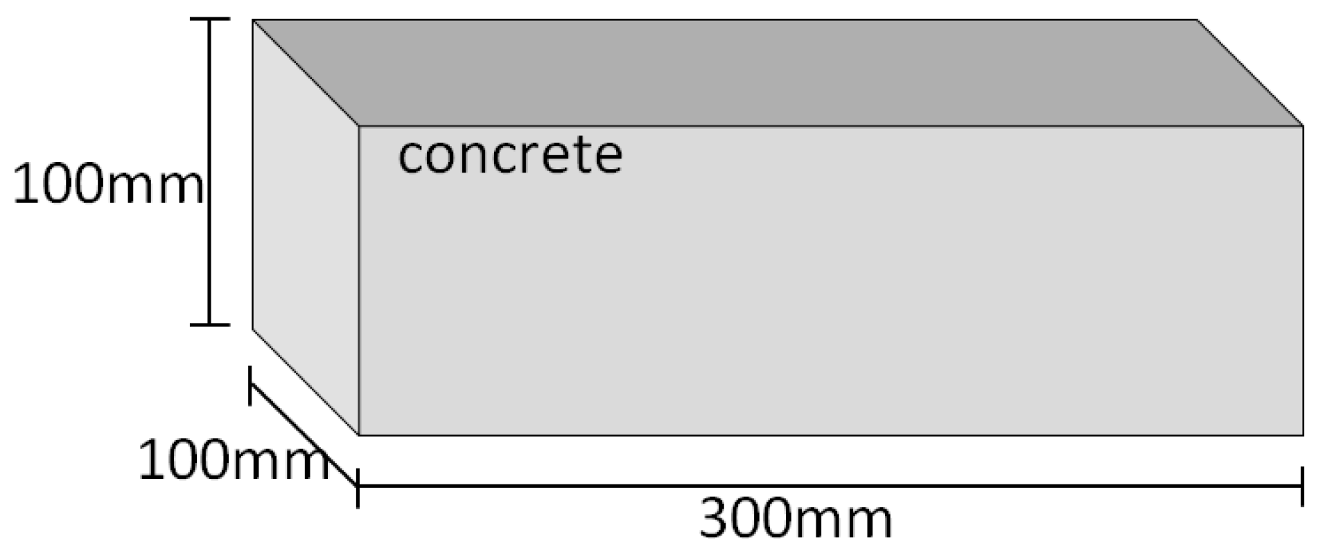
2.1. Preparation of Concrete Samples
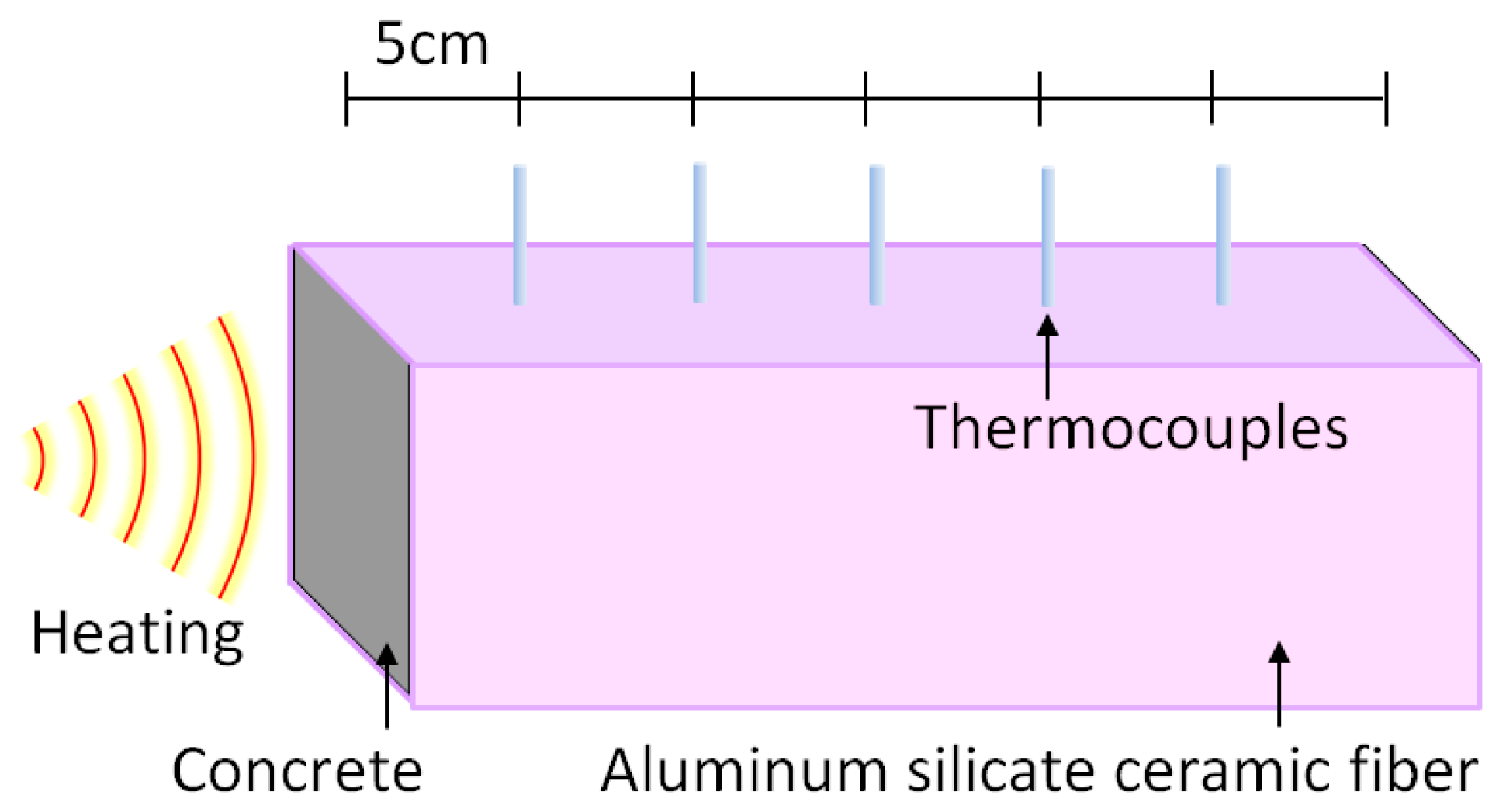
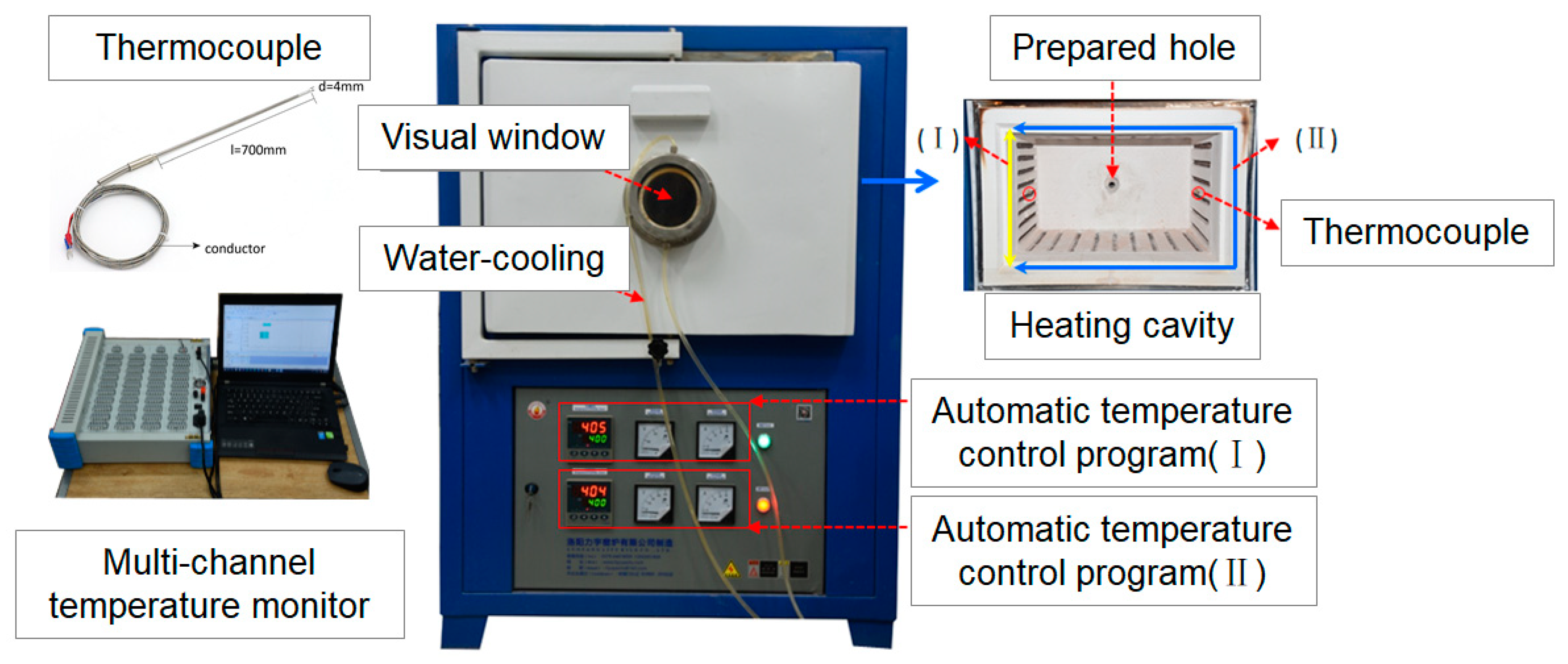
2.2. Fire Test
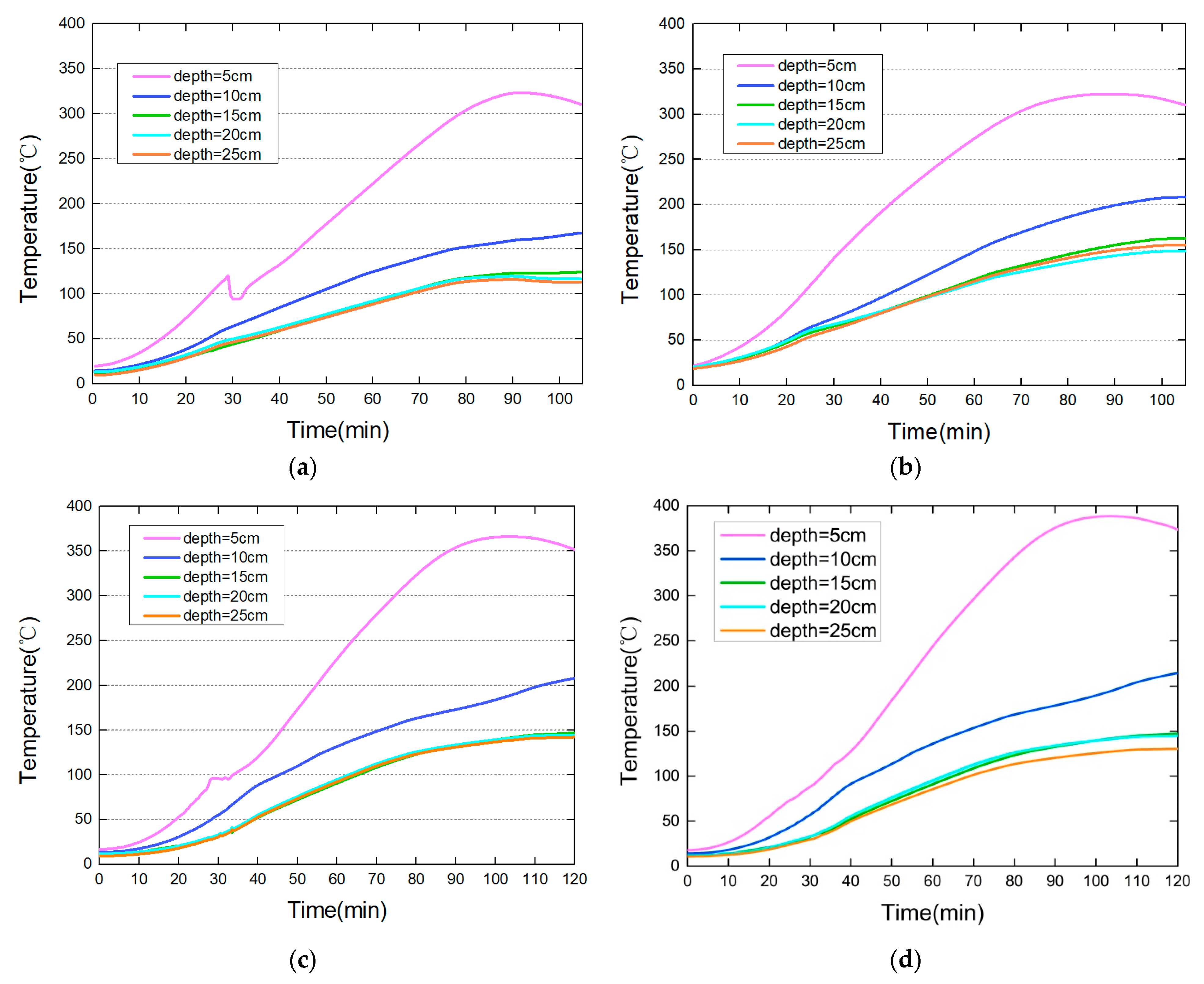
3. Experimental Results
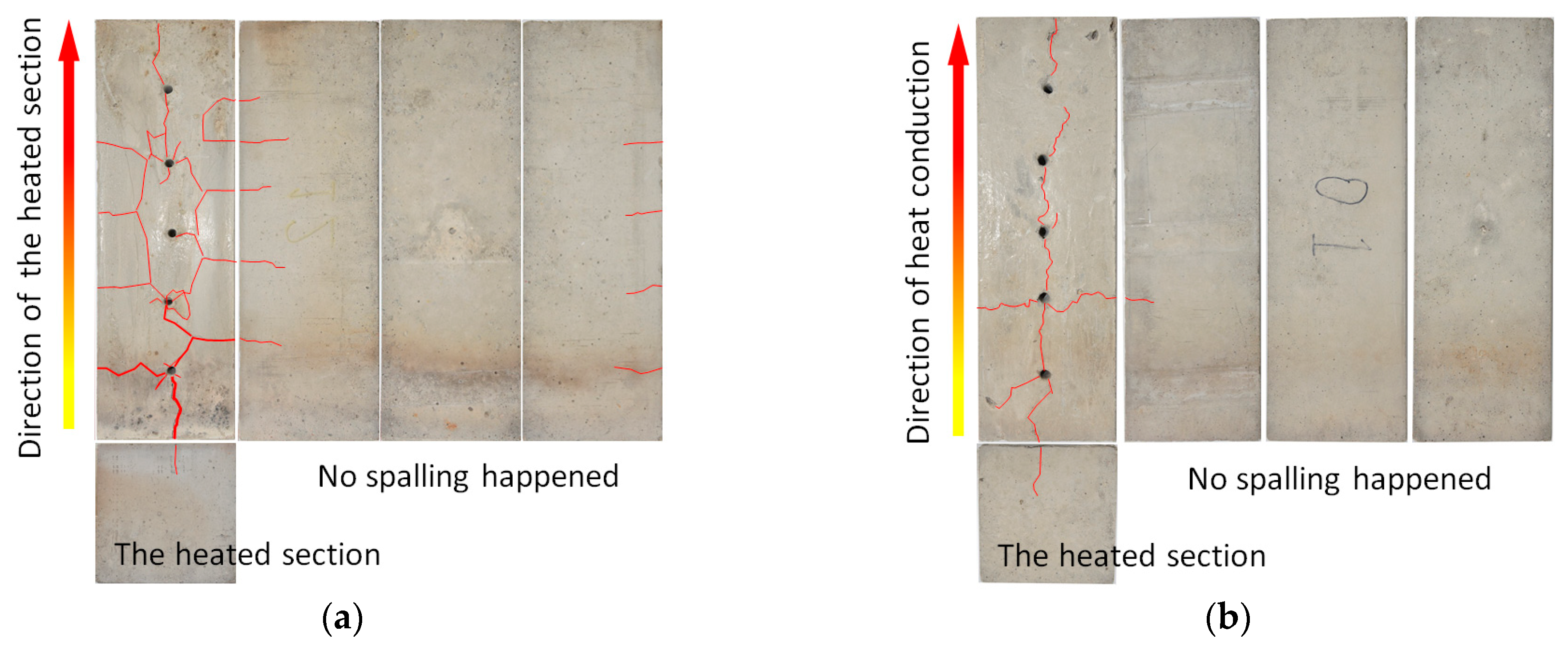
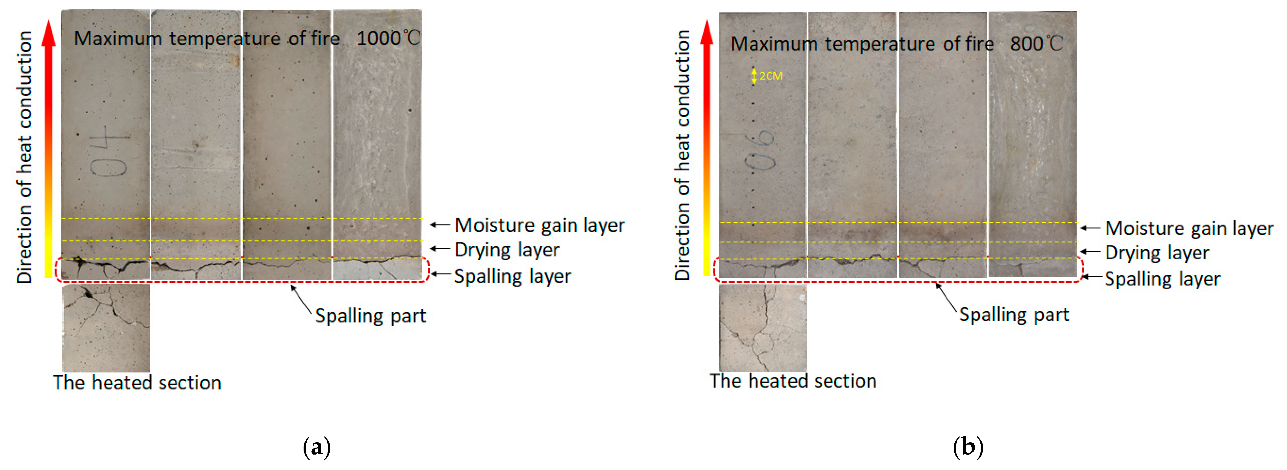
3.1. Spalling Phenomenon
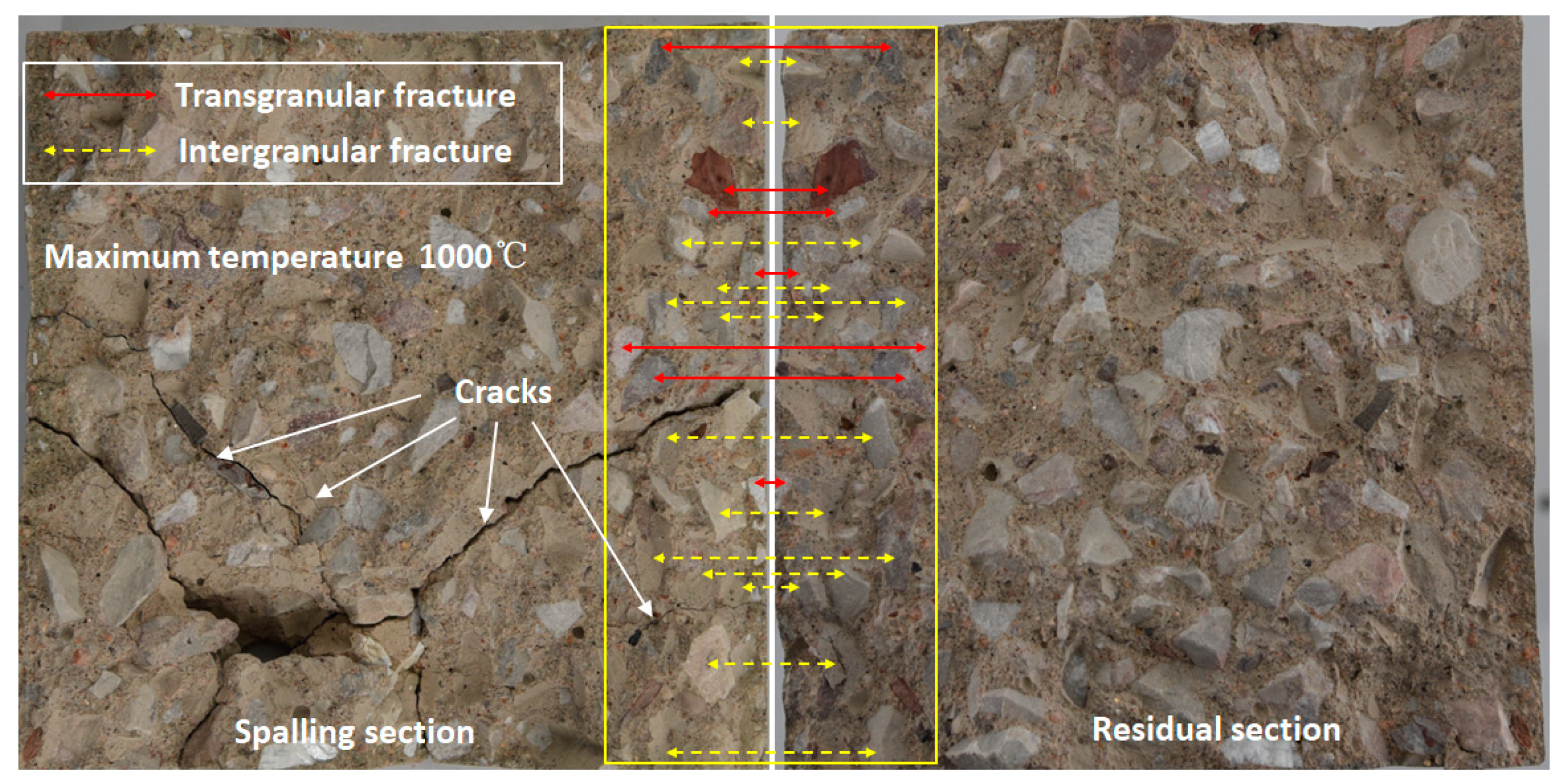
3.2. Spalling Mechanism
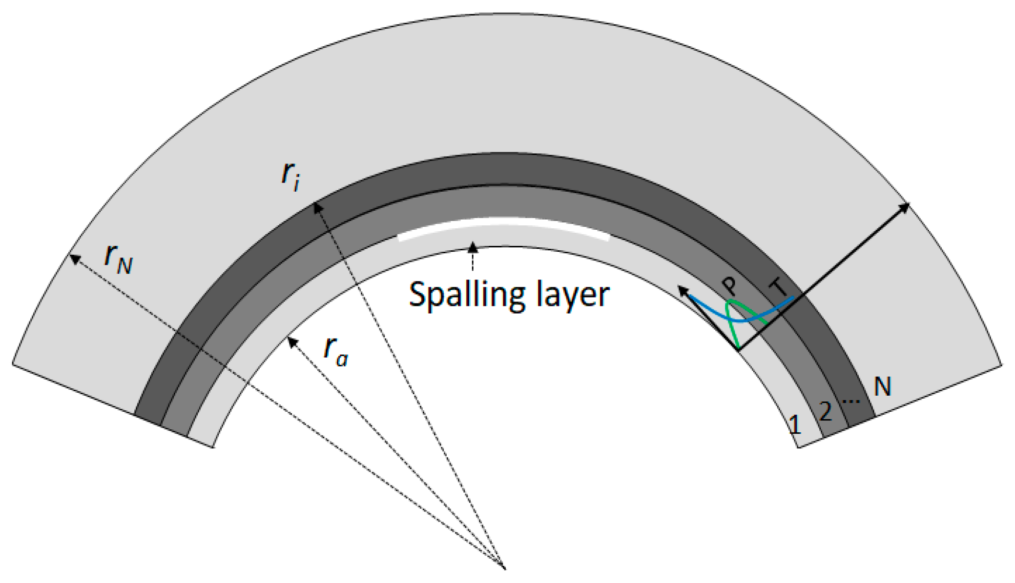
4. Analytical Prediction of Layered Spalling of Tunnel Lining
- (1)
- Governing equation of heat condition and boundary condition
- (2)
- Equilibrium equation and stress boundary conditions:
- (3)
- Laplace Transformation and series solution
5. Discussions
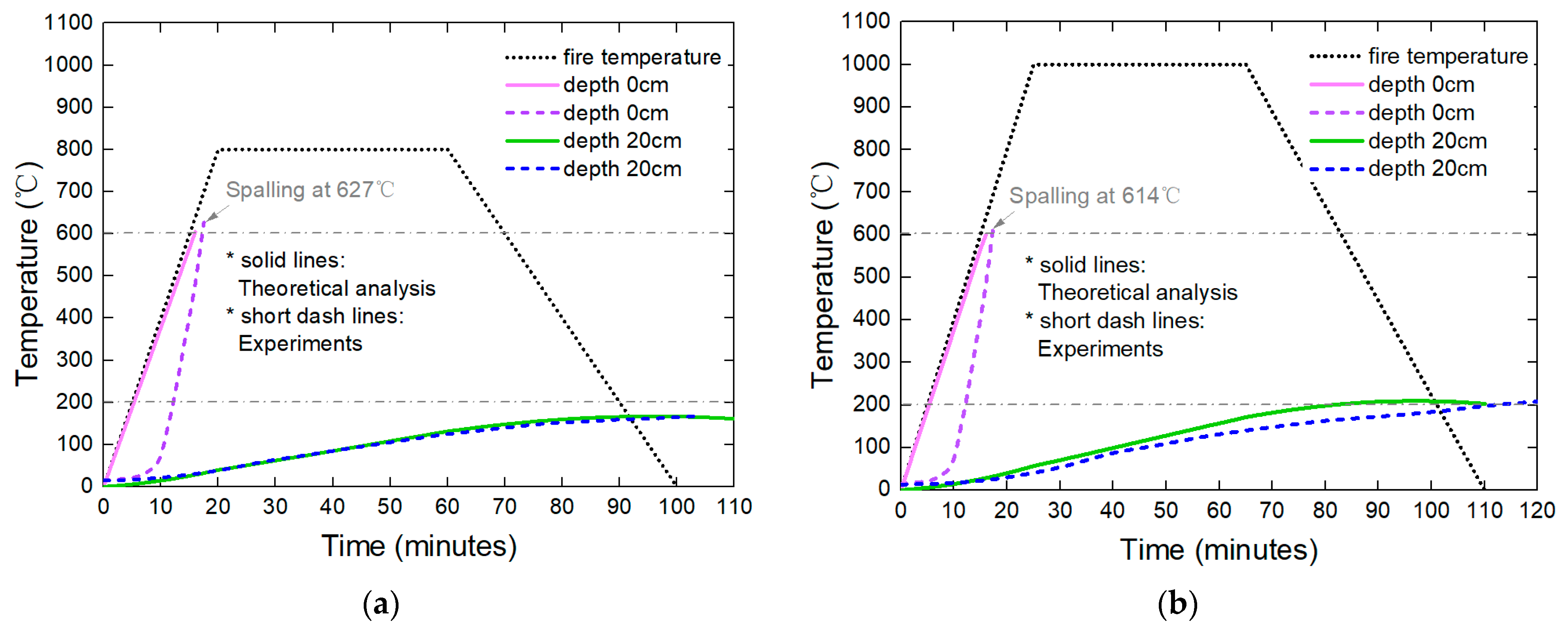
5.1. Model Validation
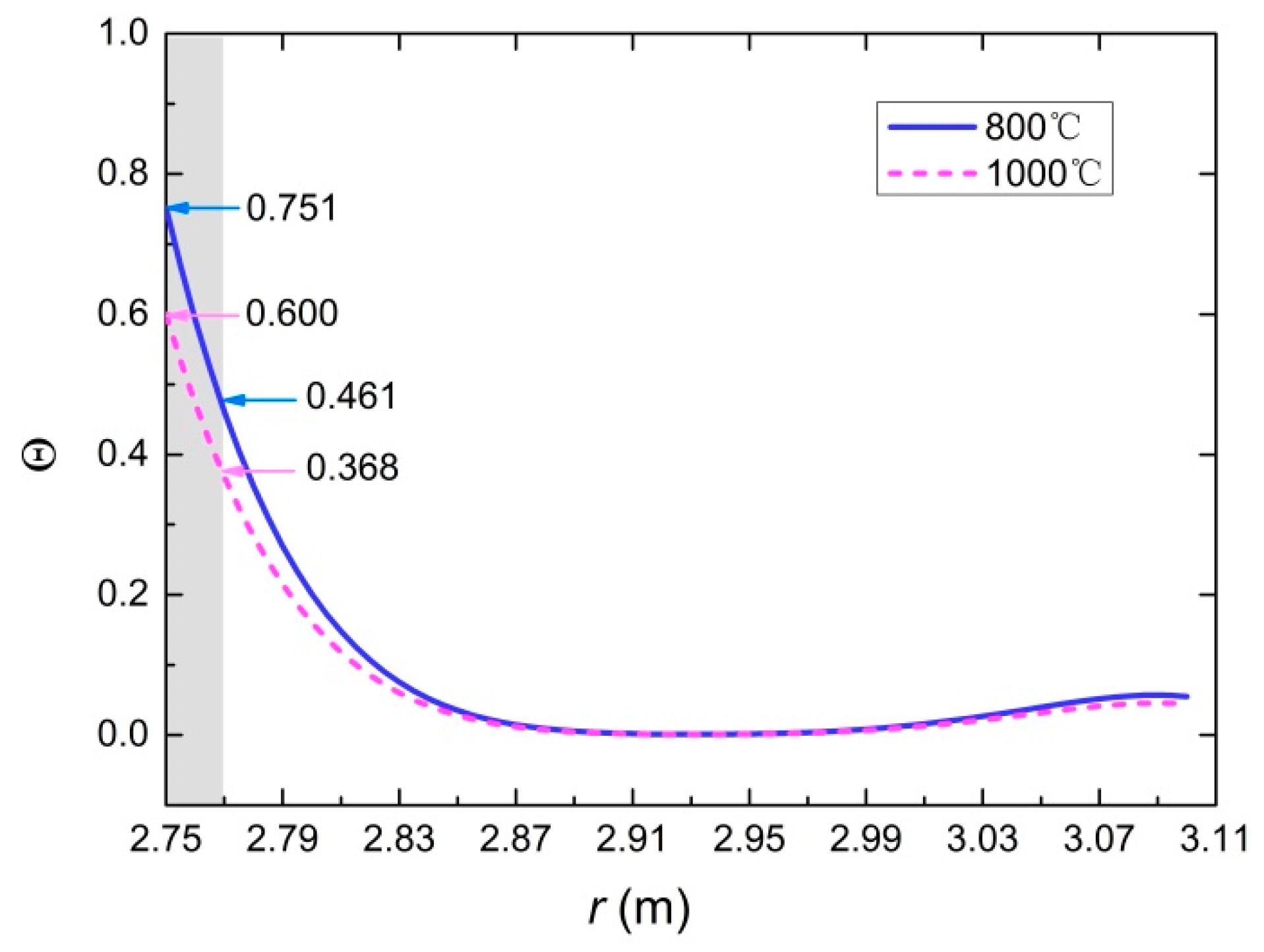
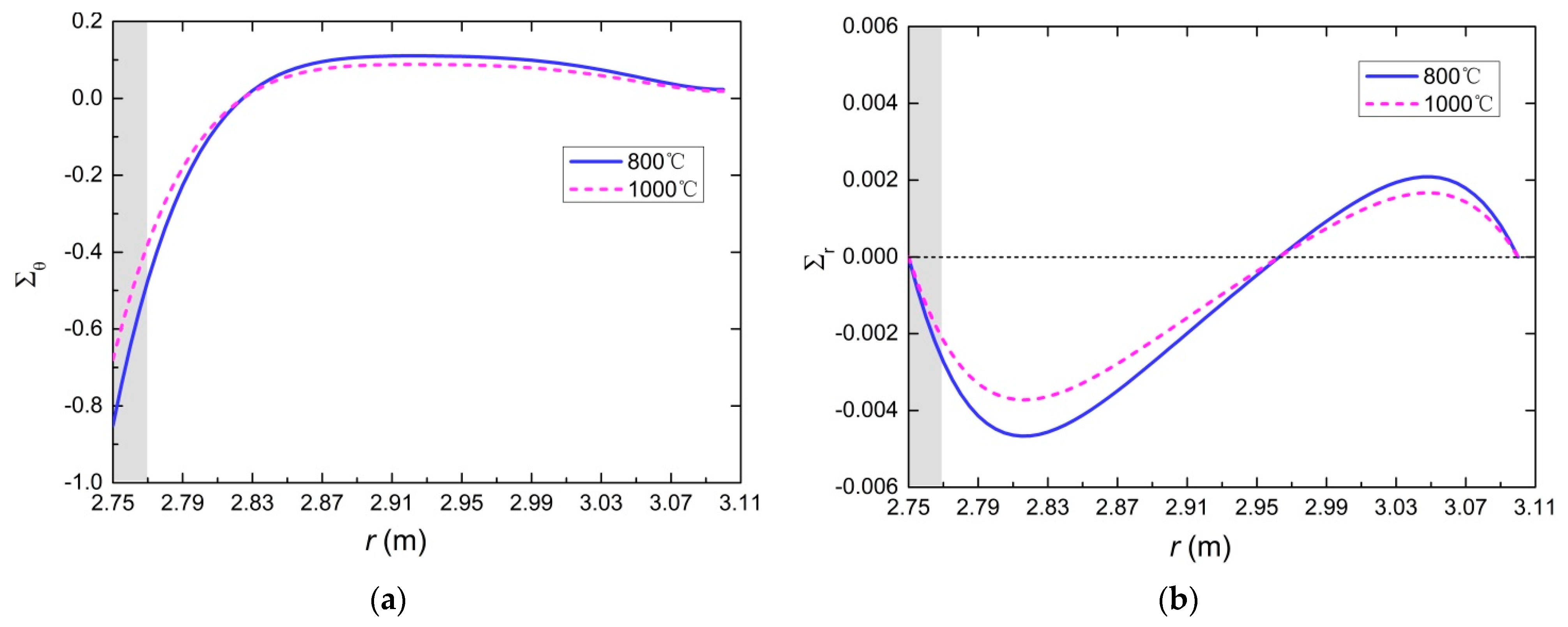
5.2. Temperature Field and Stress Field
5.3. Spalling Depth
6. Conclusions
- (1)
- The spalling characteristics of concrete under tunnel fire are summarized from the heating tests. Based on the experimental test results, the moisture content of concrete is one of the key factors of spalling. Obvious layered spalling characteristics of concrete samples without drying could be observed under the unidirectional heat conduction system. The critical temperature of spalling is 600 °C, and the thickness of the spalling layer is 2 cm~2.5 cm.
- (2)
- Based on the spalling characteristics, a multilayer model considering the spalling of concrete lining under tunnel fire is established. Time-dependent temperature, stresses, and spalling depth of tunnel lining relating to the fire temperature could be obtained by using the model proposed. This is the basis of the damage assessment of tunnel lining after fire.
- (3)
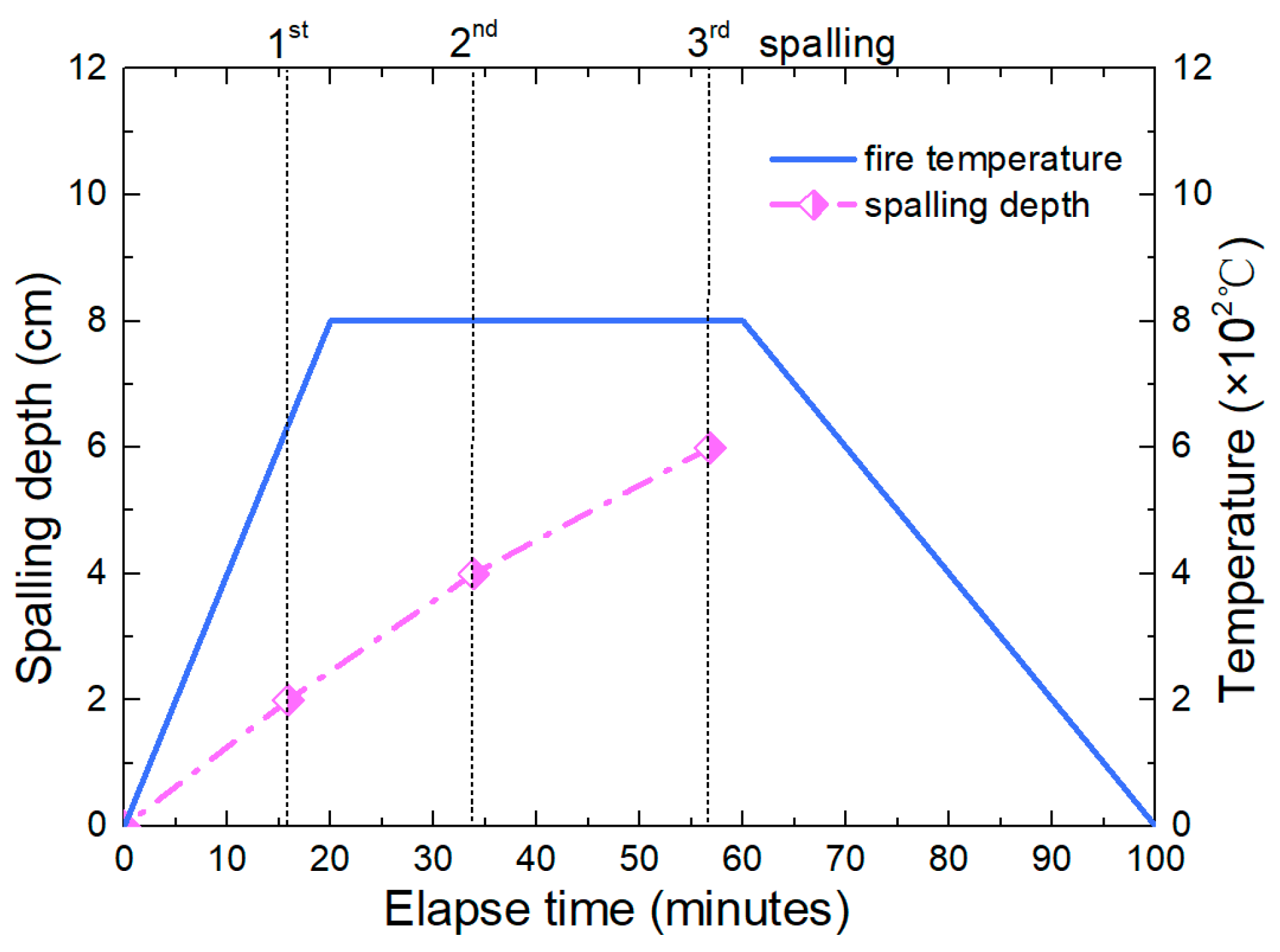
- The spalling depth increases nonlinearly with time. Before entering the cooling stage, a total of three spalling failures occurred. The temperature and the stresses induced by fire could be obtained at every time based on the model proposed in this paper.
- (4)
- It is thus clear that heat transfer analysis without considering the effects of spalling can be erroneous at high temperatures. It is therefore imperative that the estimation of the fire resistance of a secondary concrete lining at high temperatures needs to consider its spalling and cross-sectional loss.
Author Contributions
Funding
Conflicts of Interest
Appendix A
Appendix B
References
- Rui, R.; Hui, Z.; Zhao, H.; He, S.; Wang, X. Statistical analysis of fire accidents in Chinese highway tunnels 2000–2016. Tunn. Undergr. Sp. Technol. 2019, 83, 452–460. [Google Scholar]
- Beard, A.N. Fire safety in tunnels. Fire Saf. J. 2009, 44, 276–278. [Google Scholar] [CrossRef]
- Gehandler, J. Road tunnel fire safety and risk: A review. Fire Sci. Rev. 2015, 4, 2. [Google Scholar] [CrossRef] [Green Version]
- Wei, W.; Shao, Z.S.; Zhang, Y.Y.; Qiao, R.J.; Gao, J.P. Fundamentals and applications of microwave energy in rock and concrete processing-A review. Appl. Therm. Eng. 2019, 157, 113751. [Google Scholar] [CrossRef]
- Bastami, M.; Aslani, F.; Omran, M.E. High-temperature mechanical properties of concrete. Mat. Sci. Eng. A-Struct. 2010, 8, 337–351. [Google Scholar]
- Chen, B.; Liu, J. Residual strength of hybrid-fiber-reinforced high-strength concrete after exposure to high temperatures. Cem. Concr. Res. 2004, 34, 1065–1069. [Google Scholar] [CrossRef]
- Xu, S.S.; Ma, E.L.; Lai, J.X.; Yang, Y.T.; Liu, H.T.; Yang, C.P.; Hu, Q. Diseases failures characteristics and countermeasures of expressway tunnel of water-rich strata: A case study. Eng. Fail. Anal. 2022, 134, 106056. [Google Scholar] [CrossRef]
- Pichler, C.; Lackner, R.; Mang, H.A. Safety assessment of concrete tunnel linings under fire load. J. Struct. Eng. 2006, 132, 961–969. [Google Scholar] [CrossRef]
- Hua, N.; Khorasani, N.E.; Tessari, A.; Ranade, R. Experimental study of fire damage to reinforced concrete tunnel slabs. Fire Saf. J. 2022, 127, 103504. [Google Scholar] [CrossRef]
- Feist, C.; Aschaber, M.; Hofstetter, G. Numerical simulation of the load-carrying behavior of RC tunnel structures exposed to fire. Finite Elem. Anal. Des. 2009, 45, 958–965. [Google Scholar] [CrossRef]
- Ma, Q.M.; Guo, R.X.; Zhao, Z.M.; Lin, Z.W.; He, K.C. Mechanical properties of concrete at high temperature—A review. Constr. Build. Mater. 2015, 93, 371–383. [Google Scholar] [CrossRef]
- Khoury, G.A. Effect of fire on concrete and concrete structures. Prog. Struct. Eng. Mater. 2000, 2, 429–447. [Google Scholar] [CrossRef]
- Boström, L.; Larsen, C.K. Concrete for tunnel linings exposed to severe fire exposure. Fire Technol. 2006, 42, 351–362. [Google Scholar] [CrossRef]
- Choi, S.W.; Lee, J.; Chang, S.H. A holistic numerical approach to simulating the thermal and mechanical behaviour of a tunnel lining subject to fire. Tunn. Undergr. Sp. Technol. 2013, 35, 122–134. [Google Scholar] [CrossRef]
- Harmathy, T.Z. Effect of moisture on the fire endurance of building elements. ASTM Spec. Tech. Publ. 1965, 385, 74–95. [Google Scholar]
- Ali, A.Z.M.; Sanjayan, J.; Guerrieri, M. Specimens size, aggregate size, and aggregate type effect on spalling of concrete in fire. Fire Mater. 2018, 42, 59–68. [Google Scholar]
- Erdem, T.K. Specimen size effect on the residual properties of engineered cementitious composites subjected to high temperatures. Cem. Concr. Comp. 2014, 45, 1–8. [Google Scholar] [CrossRef] [Green Version]
- Maier, M.; Saxer, A.; Bergmeister, K.; Lackner, R. An experimental fire-spalling assessment procedure for concrete mixtures. Constr. Build. Mater. 2020, 232, 117172. [Google Scholar] [CrossRef]
- Gawin, D.; Pesavento, F.; Castells, A.G. On reliable predicting risk and nature of thermal spalling in heated concrete. Arch. Civ. Mech. Eng. 2018, 18, 1219–1227. [Google Scholar] [CrossRef]
- Ju, Y.; Liu, J.H.; Liu, H.B.; Tian, K.P.; Ge, Z.S. On the thermal spalling mechanism of reactive powder concrete exposed to high temperature: Numerical and experimental studies. Int. J. Heat Mass. Transf. 2016, 98, 493–507. [Google Scholar] [CrossRef]
- Zhao, J.; Zheng, J.J.; Peng, G.F.; Breugel, K.V. A meso-level investigation into the explosive spalling mechanism of high-performance concrete under fire exposure. Cem. Concr. Res. 2014, 65, 64–75. [Google Scholar] [CrossRef]
- Wei, W.; Shao, Z.; Zhang, P.; Zhang, H.L.; Cheng, J.X.; Yuan, Y. Thermally assisted liberation of concrete and aggregate recycling: A comparison between microwave and conventional heating. J. Mater. Civ. Eng. 2021, 33, 4021370. [Google Scholar] [CrossRef]
- Peng, G.F.; Yang, W.W.; Zhao, J.; Liu, Y.F.; Bian, S.H.; Zhao, L.H. Explosive spalling and residual mechanical properties of fiber-toughened high-performance concrete subjected to high temperatures. Cem. Concr. Res. 2006, 36, 723–727. [Google Scholar] [CrossRef]
- Choe, G.; Kim, G.; Yoon, M.; Hwang, E.; Nam, J.; Guncunski, N. Effect of moisture migration and water vapor pressure build-up with the heating rate on concrete spalling type. Cem. Concr. Res. 2019, 116, 1–10. [Google Scholar] [CrossRef]
- Liu, J.C.; Tan, K.H.; Yao, Y. A new perspective on nature of fire-induced spalling in concrete. Constr. Build. Mater. 2018, 184, 581–590. [Google Scholar] [CrossRef]
- Wu, K.; Shao, Z.S.; Sharifzadeh, M.; Hong, S.Y.; Qin, S. Analytical computation of support characteristic curve for circumferential yielding lining in tunnel design. J. Rock Mech. Geotech. Eng. 2022, 14, 144–152. [Google Scholar] [CrossRef]
- Fang, J.Y.; Pan, Y.; Dang, F.N.; Zhang, X.Y.; Ren, J.; Li, N. Numerical Reconstruction Model and Simulation Study of Concrete Based on Damaged Partition Theory and CT Number. Materials 2019, 12, 4070. [Google Scholar] [CrossRef] [Green Version]
- Zhang, H.L.; Davie, C.T. A numerical investigation of the influence of pore pressures and thermally induced stresses for spalling of concrete exposed to elevated temperatures. Fire Saf. J. 2013, 59, 102–110. [Google Scholar] [CrossRef] [Green Version]
- Tenchev, R.; Purnell, P. An application of a damage constitutive model to concrete at high temperature and prediction of spalling. Int. J. Solids Struct. 2005, 42, 6550–6565. [Google Scholar] [CrossRef] [Green Version]
- Ding, Z.; Li, J. A physically motivated model for fatigue damage of concrete. Int. J. Damage Mech. 2017, 27, 1192–1212. [Google Scholar]
- Hu, W.L.; Cheng, W.C.; Wen, S.J.; Rahman, M. Effects of chemical contamination on microscale structural characteristics of intact loess and resultant macroscale mechanical properties. Catena 2021, 203, 105361. [Google Scholar] [CrossRef]
- Yan, Z.G.; Zhang, Y.; Shen, Y.; Zhu, H.H.; Lu, Y. A multilayer thermo-elastic damage model for the bending deflection of the tunnel lining segment exposed to high temperatures. Tunn. Undergr. Sp. Technol. 2020, 95, 103142. [Google Scholar] [CrossRef]
- Savov, K.; Lackner, R.; Mang, H.A. Stability assessment of shallow tunnels subjected to fire load. Fire Saf. J. 2005, 40, 745–763. [Google Scholar] [CrossRef]
- Cheng, P.; Zhu, H.; Zhang, Y.; Jiao, Y.; Fish, J. Coupled thermo-hydro-mechanical-phase field modeling for fire-induced spalling in concrete. Comput. Method. Appl. Mech. Eng. 2022, 389, 114327. [Google Scholar] [CrossRef]
- Chang, S.H.; Choi, S.W.; Lee, J. Determination of the combined heat transfer coefficient to simulate the fire-induced damage of a concrete tunnel lining under a severe fire condition. Tunn. Undergr. Sp. Technol. 2016, 54, 1–12. [Google Scholar] [CrossRef]
- Hager, I. Colour Change in Heated Concrete. Fire Technol. 2014, 50, 945–958. [Google Scholar] [CrossRef] [Green Version]
- Du, S.; Zhang, Y.C.; Sun, Q.; Guo, W.Y.; Geng, J.S.; Zhang, K.J. Experimental study on color change and compression strength of concrete tunnel lining in a fire. Tunn. Undergr. Sp. Technol. 2018, 71, 106–114. [Google Scholar] [CrossRef]
- Qiao, R.J.; Shao, Z.S.; Yuan, Y.; Zhou, H.; Guo, Y.B. An analysis model for the temperature and residual stress of tunnel liner exposed to fire. Arch. Civ. Mech. Eng. 2021, 21, 158. [Google Scholar] [CrossRef]
- Qiao, R.J.; Shao, Z.S.; Liu, F.Y.; Wei, W. Damage evolution and safety assessment of tunnel lining subjected to long-duration Fire. Tunn. Undergr. Sp. Technol. 2019, 83, 354–363. [Google Scholar] [CrossRef]
- Yan, Z.G. A Study on Mechanical Behaviors and Fire Proof Methods of Tunnel Lining Structure during and after Fire Scenarios. Doctoral Dissertation, Tongji University, Shanghai, China, 2007. [Google Scholar]


| Concrete | w/c Ratio | Mass (kg/m3) | ||||||
|---|---|---|---|---|---|---|---|---|
| Cement | Water | Sand | Aggregate | Fly Ash | Expansive Agent | Admixture | ||
| C40P8 | 0.427 | 331 | 183 | 734 | 1057 | 83 | 22 | 7.8 |
| Number | ||||
|---|---|---|---|---|
| Specimen | Maximum Temperature of 800 °C | Maximum Temperature of 1000 °C | ||
| Without Drying | With Drying | Without Drying | With Drying | |
| 5 monitoring holes in specimen | 3 | 3 | 3 | 3 |
| 0 monitoring hole in specimen | 3 | 3 | 3 | 3 |
| 1 monitoring hole in specimen | 3 | 0 | 3 | 0 |
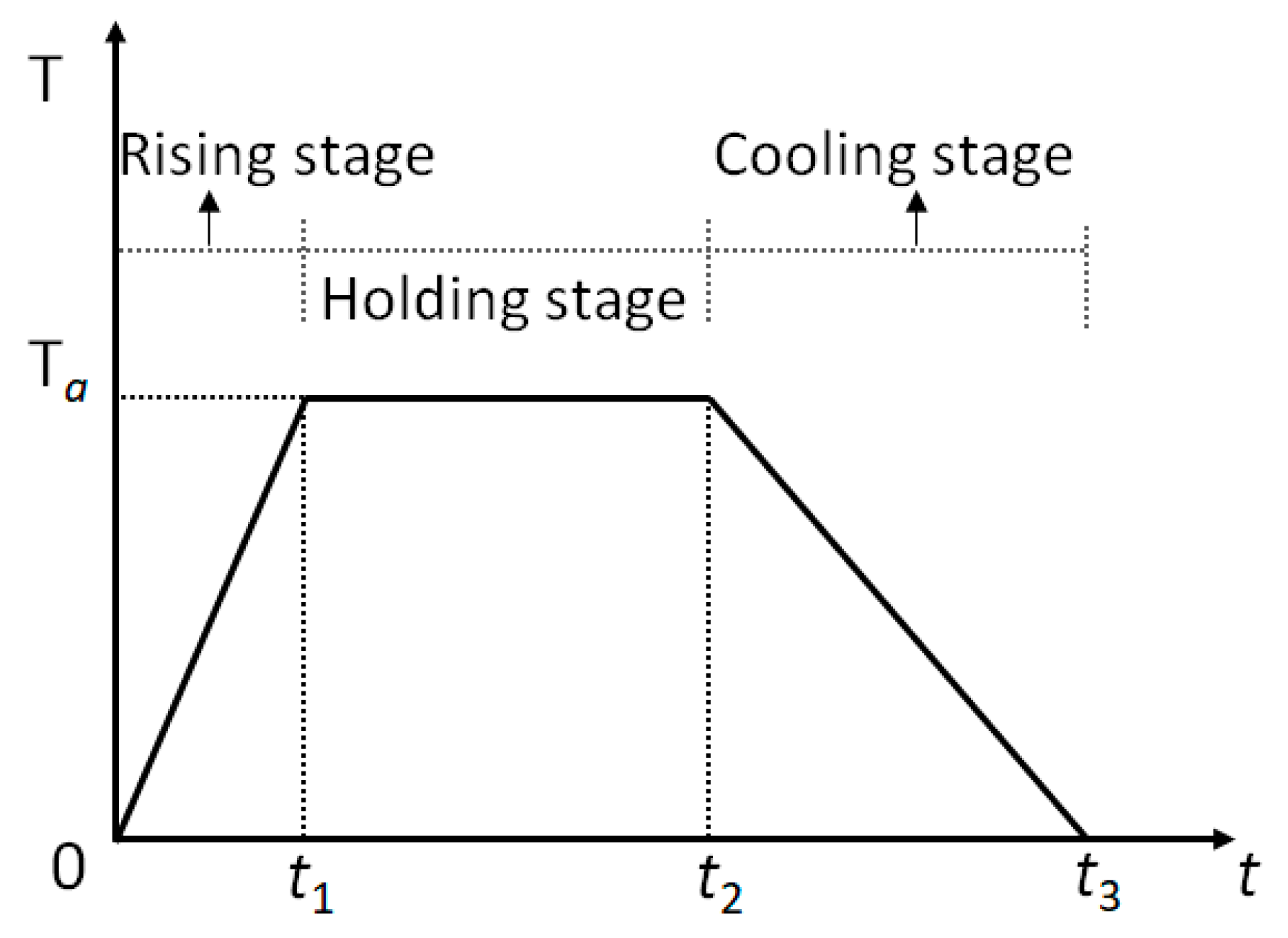
| Heating Rate | Maximum Temperature | Holding Time | Cooling Mode | |
|---|---|---|---|---|
| Case 1 | 40 °C/min | 800 °C | 30 min | Natural cooling |
| Case 2 | 40 °C/min | 1000 °C | 30 min | Natural cooling |
| Parameter | Temperature Dependence | In Put (at 20 °C) |
|---|---|---|
| Elastic modulus, E (GPa) | / | 30 |
| Poisson’s ratio, μ | / | 0.2 |
| Thermal expansion coefficient, α (/K) | / | 1 × 10⁻⁵ |
| Density, ρ (Kg/m3) | / | 2400 |
| Thermal conductivity coefficient, λ (W/(m·K)) | 1.883 [40] | |
| Specific heat capacity, c (J/(kg·K)) | 836.8 + 0.4922 T | 913 [40] |
Publisher’s Note: MDPI stays neutral with regard to jurisdictional claims in published maps and institutional affiliations. |
© 2022 by the authors. Licensee MDPI, Basel, Switzerland. This article is an open access article distributed under the terms and conditions of the Creative Commons Attribution (CC BY) license (https://creativecommons.org/licenses/by/4.0/).
Share and Cite
Qiao, R.; Guo, Y.; Zhou, H.; Xi, H. Explosive Spalling Mechanism and Modeling of Concrete Lining Exposed to Fire. Materials 2022, 15, 3131. https://doi.org/10.3390/ma15093131
Qiao R, Guo Y, Zhou H, Xi H. Explosive Spalling Mechanism and Modeling of Concrete Lining Exposed to Fire. Materials. 2022; 15(9):3131. https://doi.org/10.3390/ma15093131
Chicago/Turabian StyleQiao, Rujia, Yinbo Guo, Hang Zhou, and Huihui Xi. 2022. "Explosive Spalling Mechanism and Modeling of Concrete Lining Exposed to Fire" Materials 15, no. 9: 3131. https://doi.org/10.3390/ma15093131
APA StyleQiao, R., Guo, Y., Zhou, H., & Xi, H. (2022). Explosive Spalling Mechanism and Modeling of Concrete Lining Exposed to Fire. Materials, 15(9), 3131. https://doi.org/10.3390/ma15093131