Article

Lithium-Rich Rock Salt Type Sulfides-Selenides (Li2TiSexS3−x): High Energy Cathode Materials for Lithium-Ion Batteries

CEA, LITEN, University Grenoble Alpes, F-38054 Grenoble, France
*
Author to whom correspondence should be addressed.
Materials 2022, 15(9), 3037; https://doi.org/10.3390/ma15093037
Submission received: 9 March 2022 / Revised: 15 April 2022 / Accepted: 19 April 2022 / Published: 22 April 2022
(This article belongs to the Special Issue Development of Sustainable Battery Materials)

Abstract

:
Lithium-rich disordered rocksalt Li2TiS3 offers large discharge capacities (>350 mAh·g−1) and can be considered a promising cathode material for high-energy lithium-ion battery applications. However, the quick fading of the specific capacity results in a poor cycle life of the system, especially when liquid electrolyte-based batteries are used. Our efforts to solve the cycling stability problem resulted in the discovery of new high-energy selenium-substituted materials (Li2TiSexS3−x), which were prepared using a wet mechanochemistry process. X-ray diffraction analysis confirmed that all compositions were obtained in cation-disordered rocksalt phase and that the lattice parameters were expanded by selenium substitution. Substituted materials delivered large reversible capacities, with smaller average potentials, and their cycling stability was superior compared to Li2TiS3 upon cycling at a rate of C/10 between 3.0–1.6 V vs. Li+/Li.

1. Introduction

The rapid growth in electric vehicle market requires high performance, safe, and low-cost battery packs that should enable driving ranges exceeding 500 km. Current Li-Ion battery positive electrode materials can realize this objective by providing specific energies that exceed 250 Wh·kg−1 at cell level [1,2,3,4]. These materials still contain a small percentage of cobalt, and the concerns related to this critical element have increased, due to its price and availability. Recent research efforts have focused on the discovery of Co-poor or even Co-less positive electrode materials and the development of alternative high-energy materials, such as lithium sulfide and cation-disordered rocksalts [5,6,7,8,9,10,11,12,13,14,15,16,17,18,19,20]. Among them, cation-disordered rocksalts have recently received great interest, as a new generation of positive electrode materials for lithium ion batteries [16,17,21,22]. For instance, disordered rocksalt sulfides deliver high specific capacities (>400 mAh·g−1) at relatively low operating potentials (~2.2 V vs. Li+/Li), and their energy density is competitive with conventional layered materials [19]. This low operating potential may be considered an advantage of sulfide-type batteries, since they do not experience the serious electrolyte degradation problems occurring at higher voltages [23]. In addition, these materials allow the exchange of more than one Li per metal cation (multi-electrons redox reactions); thus, greater capacities could be produced [19,24,25]. Such a property was already noticed and reported in earlier studies, as TiS3 was able to host three Li+ ions during discharge [26,27]. However, only one lithium ion was reversibly intercalated [26].
More recently, new studies have paved the way for the discovery of novel Li-rich disordered rocksalt sulfides. Sakuda et al. highlighted that Li2TiS3 and Li3NbS4 materials with a disordered rocksalt cubic structure can provide capacities above 400 mAh·g−1 upon cycling between 3–1.5 V vs. Li+/Li [19,24]. Despite their promising reversible capacities, the retention performances of Li2TiS3 and Li3NbS4 were rather poor in conventional cells; on the contrary, superior retention performances were achieved in solid-state cells [16]. For industrial applications, materials should have both a long shelf life and a high capacity. The retention performance of Li2TiS3 is a major bottleneck, and new approaches are necessary to improve this. Partial substitution mechanisms may be promising solutions for this issue. For instance, sulfur anions could be replaced with an alternative anion. Studies show that selenium substitution can improve the cycling stability of Li2S cells [28,29]; therefore, such results motivated us to substitute sulfur with selenium in Li2TiS3. Thanks to an optimized wet milling process, two new lithium-rich rock salt type sulfides–selenides compounds (Li2TiSexS3−x) are reported in this study, for the first time. Structural investigations, as well as electrochemical tests have been performed, to compare the mechanism of lithium insertion/extraction between these new compounds and the previously published Li2TiS3 cathode material [19].

2. Materials and Methods

2.1. Wet Mechanochemical Synthesis of Li2TiSexS3−x

According to the synthesis procedure; 1.5 g of precursors composed of lithium sulfide (Li2S, Sigma Aldrich, St. Louis, MO, USA, 98%), titanium powder (Alfa Aesar, Havrier, MA, USA, 99.98%), sulfur powder (Sigma Aldrich, 99.99%), and selenium powder (Alfa Aesar, 99.9%) precursors were placed into a 50-mL zirconia jar that contained 285 zirconia balls (5 mm in diameter). Then, an appropriate amount of anhydrous hexane (99.9%, Sigma Aldrich) was added, until covering the entire ball surface. Afterwards, the jar was closed tightly and transferred from an argon-filled glovebox to the planetary ball milling machine (Retsch PM 100). Milling was operated at 510 rpm for 20 hours. Powder was recovered in an argon-filled glovebox, to limit air contamination in the powders. Zirconia impurities due to high-energy milling were checked using inductively coupled plasma atomic emission spectroscopy measurements and were considered low (0.018 mole of ZrO2 for 1 mole of Li2TiS3).

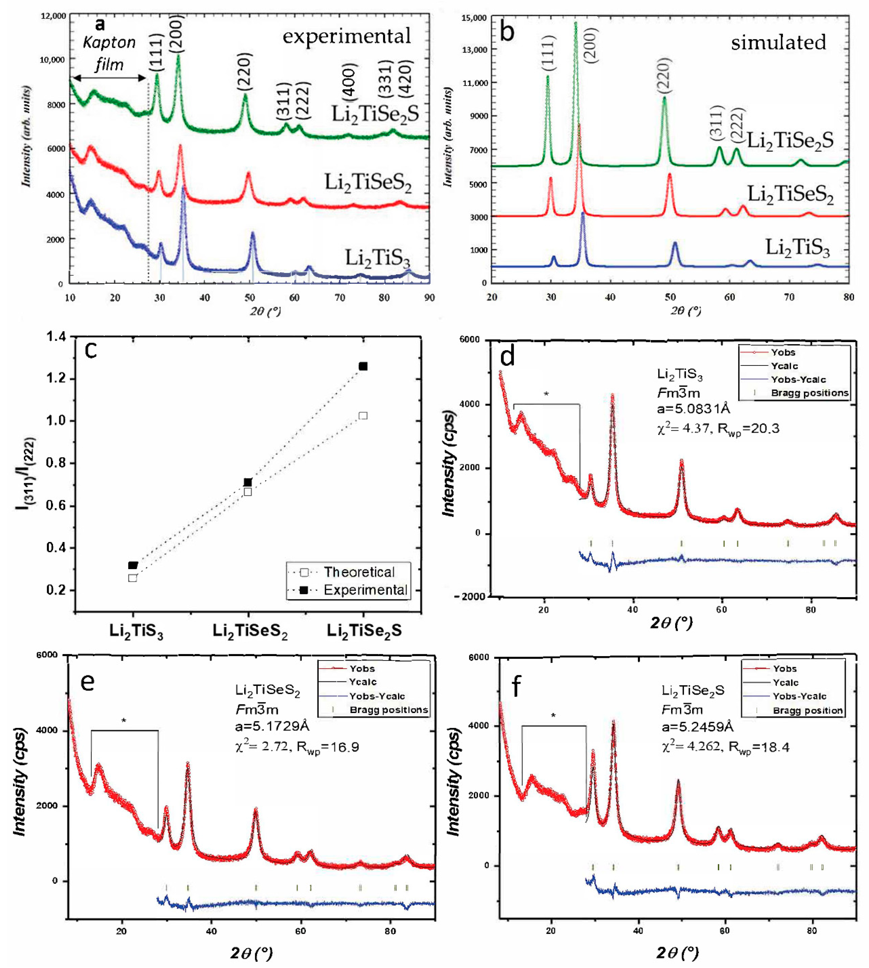
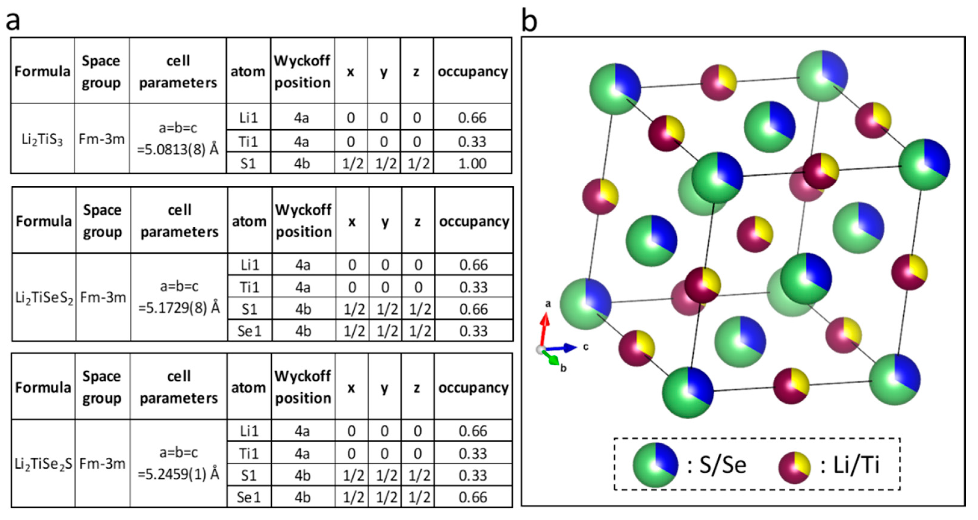
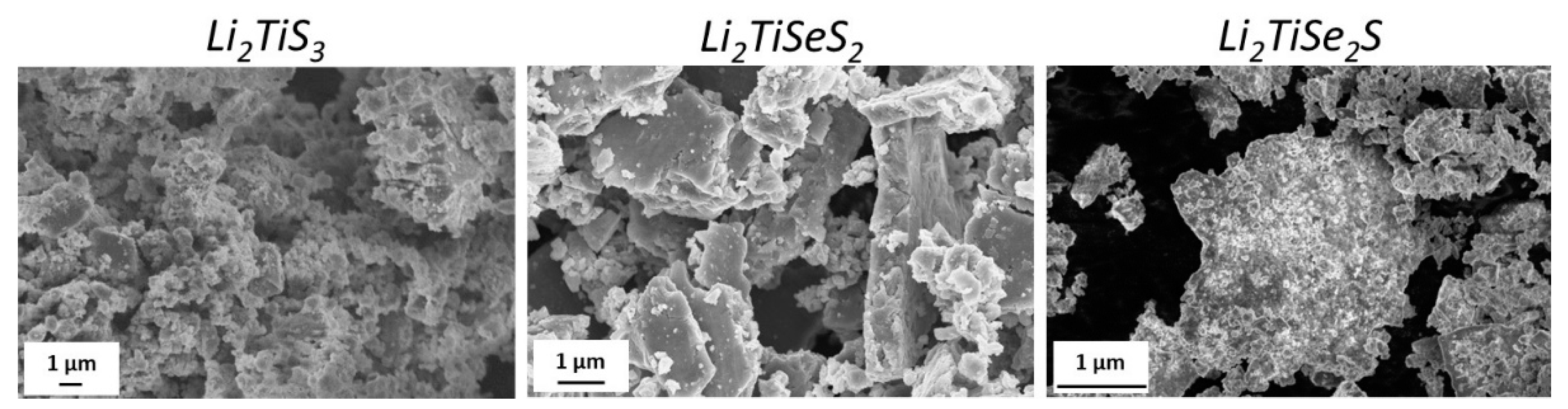
2.2. Structural Characterizations

X-ray diffraction (XRD) analyses were carried out on a BRUKER AXS D8 diffractometer, using Cu Kα (λ = 1.5406 Å) anticathode, where the sample was scanned in the range of 8–80° using a step size of 0.02°. As the sulfide materials are air sensitive, all of the samples were prepared in a glovebox, and the sample surface was protected with Kapton®. A signal due to Kapton® film could be detected at small 2θ angles (0–28°) in the diffraction patterns of the powders.
Scanning electron microscopy (SEM) and energy-dispersive X-ray spectroscopy (EDX) were performed with a microscope, Zeiss brand MEB LEO 1530 Gemini.
Chemical characterization by X-ray photoelectron spectroscopy (XPS) was carried out using a Versaprobe II ULVAC-PHI spectrometer. A monochromatic beam (X-ray source Al Kα 1486.6 eV) of 100 μm diameter and 25 W of power was focused on the surface of the samples. Survey spectra were measured over a spectral range of 0−1200 eV, to identify the elements present in the material using a pass energy of 117 eV, which corresponds to a resolution of 1.6 eV. High resolution spectral analyses were performed using a pass energy of 23 eV, which corresponds to a resolution of 0.5 eV. All XPS measurements were carried out in an ultrahigh vacuum chamber (7 × 10⁻¹⁰ mbar). All XPS spectra binding energies were corrected using the C1s line of alkyl groups in the C-C at 285.0 eV. Curve fitting and background subtraction were accomplished using Casa XPS software. The spectra curve fitting was performed using the pseudo-Voigt function, product of Gaussian (80%), and Lorentzian (20%) distributions.

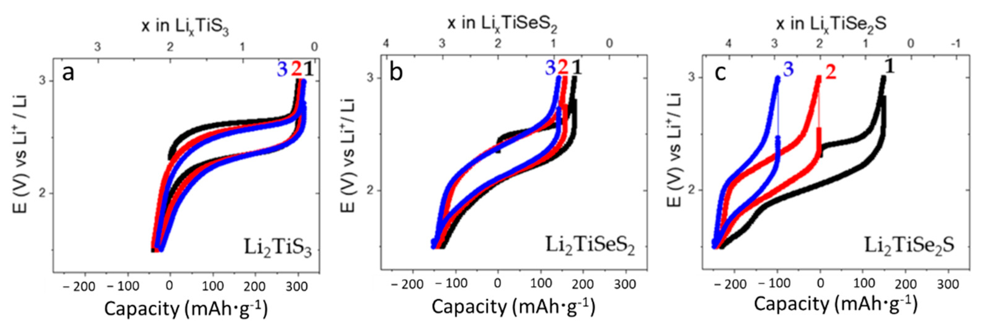
2.3. Electrochemical Characterizations

Electrode preparation: In an Ar-filled glove box, positive electrodes were prepared using 80 wt.% of the active material, 10 wt.% Carbon SuperP (Timcal, Willebroek, Belgium), 10 wt.% of PVdF (Solvay, Brussels, Belgium). An adequate amount of NMP (Sigma Aldrich) was added, to form a uniform slurry, then it was coated on an aluminum foil (20 μm) using a 100 µm doctor blade and left to dry in the glovebox for three days. The electrodes were cut (14 mm diameter), pressed (10 t), weighed (loaded > 2 mg) in the glovebox, and dried in a Buchi® oven at 60 °C for 12 h under vacuum.
Electrochemical testing: Coin cells were prepared using 14-mm diameter positive electrodes, 16-mm diameter Li foil as a negative electrode, and 150 μL electrolyte containing 1 M LiPF6 in EC:PC:DMC, where EC: ethylene carbonate; PC: propylene carbonate; DMC: dimethyl carbonate, in a volumetric ratio of 1:1:3, respectively. A propylene separator (Celgard® 2400, 16.5 mm diameter) and polyolefin separator (Viledon®, 16.5 mm diameter) were used in the coin cells. Three-coin cells were cycled at 22 °C, at a rate of C/10 between 3 V and 1.5 V, using ARBIN cycling instrumentation.

3. Results

To prepare selenium substituted Li2TiS3 compositions (Li2TiSexS3−x), we developed a flexible and easy process utilizing ball-milling, in which precursors are used in their neutral form, as neither Li2Se nor TiSe2 precursors were commercially available [30]. Our synthesis process does not require applying multiple steps to prepare the ceramic powders [28]. The powder diffraction patterns of the three resulting powders (Li2TiSexS3−x) are presented in Figure 1a.
With our original synthesis process (wet mechanochemistry), Li2TiS3 was successfully prepared as a disordered rocksalt phase. Selenium substituted samples showed a similar peak profile as Li2TiS3, indicating that Li2TiSexS3−x compositions were also prepared in disordered rocksalt phase.
At first observation, the diffraction peaks of Li2TiSeS2 and Li2TiSe2S patterns shifted to small 2θ angles, indicating that the lattice parameters expanded with selenium substitution. This behavior was expected, as Se2− is bigger than S2−. The lattice parameters of Li2TiSexS3−x powders were refined with Rietveld refinement in the Fullprof program [31]. All of the peak profiles are illustrated in Figure 1d–f, and the refined parameters and the resulting structure is shown in Figure 2. The lattice parameters of Li2TiS3 (5.0831(8) Å) were found to be slightly bigger than those previously reported (5.05 Å) [16]. Second, lattice parameters of Li2TiSeS2 and Li2TiSe2S were found (5.1729(8) Å) and (5.2459(1) Å), respectively.
In addition, the peak intensity ratios of Li2TiSeS2 and Li2TiSe2S differed from the peak intensity ratio of Li2TiS3 powder, as can be clearly seen on the intensity of the (311) and (222) reflections around 60°. We, thus, simulated the diffraction patterns of Li2TiSeS2 and Li2TiSe2S using the refined cell parameters and a similar structure as for Li2TiS3 (Figure 1b). The same evolution in peak intensity ratios was observed with selenium substitution, confirming the Se substitution. For the Rietveld refinements, owing to the poor crystallinity of the material and the presence of a broad signal coming from the Kapton® protective film, it was decided to not refine the atomic occupancies and keep the model structures. However, without further refining, the agreement between the observed and calculated pattern was already quite good and confirmed that Se substitution had occurred in these samples.
The Figure 3 shows SEM images of Li2TiSexS3−x powders.
All powders were composed of agglomerates of primary nanoparticles, and, curiously, the Li2TiSeS2 agglomerates tended to have a plate-like morphology.
The electrochemical performances of Li2TiS3 and selenium-substituted samples (Li2TiSeS2 and Li2TiSe2S) were investigated and compared in half-cells (Figure 4).
The open circuit potential of Li2TiS3 was measured as 2.31 V at the beginning of the cycling. When the Li2TiS3 was charged with a C-rate of C/10 until 3 V, the 1.77 Li+ ions were extracted from Li2TiS3 and a capacity of 300 mAh·g−1 was delivered. During discharge, 2.0 Li+ ions were inserted into the structure, the composition changed into Li2.23TiS3, and a capacity of 339 mAh·g−1 was delivered. The average charge and discharge potentials were measured at 2.46 V and 2.23 V, respectively, and a summary of the results is shown in Table 1.
The Li2TiS3 material prepared using our original synthesis process delivered greater charge capacities, but slightly smaller discharge capacities, than the Li2TiS3 material previously reported [16]. Moreover, we observed that Li2TiS3 provided a greater discharge capacity at the initial cycle, but the charge–discharge curve was fully reversible at the end of the second and third cycles.
Charge: Li2Ti4+S32− → Li0.23Ti4+(S2−)1.23(S22−)0.885 + 1.77 Li+ + 1.77 e
Discharge: Li0.23Ti4+(S2−)1.23(S22−)0.885 + 2 Li+ + 2 e→ Li2.23(Ti4+)x(Ti3+)1−x(S2−)3−y(S22−)y
with 2·(0.885 − y) + x = 2.
Such greater discharge capacity at the initial cycle was previously reported for both Li2TiS3 and other compositions (Li3NbS4 and Li3SnS4) [16,24,25]. We have to keep in mind that this phenomenon will require the addition of “lithium sacrificial salt” inside Li-ion cells if this material is used in front of a graphite anode instead of metal lithium. Another way to overcome this phenomenon could be to use the material in all solid-state batteries, with metal lithium as anode. In all cases, the origin of the extra capacity remains unknown, and further structural analyses are needed to explain it.
We explain the possible redox mechanism in Li2TiS3 with a hypothesis whereby all the atoms are stabilized at their valence states (Ti4+ and S2−) in the pristine electrode, and there is no loss of sulfur atoms during the charge–discharge process. Based on this hypothesis, only sulfur redox should be active during charging, since Ti is already at its maximum valence of Ti4+. Therefore, charge capacity may have been produced by anionic (sulfur) redox, with some part of the S2− atoms oxidized into S22 (Equation (1)). Moreover, the discharge capacity could have been provided by either anionic redox (S2−/S22−) or both anionic and cationic (Ti4+/Ti3+) redox processes. A reversible sulfur redox process was previously mentioned in the literature [32]. Reversible formation and dissociation of covalent S-S bonds in an Li2TiS3 electrode were detected in both pair distribution function analyses and ab initio molecular dynamics calculations, and this was later attributed to reversible sulfur redox processes.
Li2TiSeS2 and Li2TiSe2S cells were also tested with the same cycling schedule applied to Li2TiS3 cells, and 179 mAh·g−1 charge and 310 mAh·g−1 discharge capacities were delivered between 3 and 1.5 V vs. Li+/Li. The average charge and discharge potentials were measured to be 2.34 V and 2.06 V, respectively, indicating that the average potentials are reduced by selenium substitution. At the end of the first cycle, we again detected a large discharge capacity. More than 2.0 Li+ ions were inserted into the structure, and the composition changed into Li3.08TiSeS2, which can be regarded as the average (theoretical) composition. Such capacity was even greater than the theoretical capacity of Li2TiSeS2 cells (261 mAh·g−1 based on two electron exchange processes). At the subsequent cycles, a reversible cycling curve was observed. If we keep the same hypothesis that we previously used to explain the redox process of Li2TiS3 cells, the charge capacity should be produced by either sulfur (S2/S22) or selenium (Se2/Se22) redox processes, which is active between 3 and 1.5 V [29,30]. Here, again, the discharge capacity should be provided by either anionic (S2/S22 or Se2/Se22) or both anionic and cationic (Ti4+/Ti3+) redox processes.
Li2TiSe2S cells delivered charge and discharge capacities of 149 mAh·g−1 and 379 mAh·g−1, respectively. Much lower average charge and discharge potentials (2.24 V and 1.98 V) were detected. At the end of the initial discharge, 3.44 Li+ ions were inserted into the cubic rocksalt structure of Li2TiSe2S, and the theoretical composition became equivalent to Li4.17TiSe2S. We again detected extra discharge capacity, and this was even greater than the theoretical capacity of Li2TiSe2S (213 mAh·g−1 based on two electron exchange processes). Now, we cannot explain more than a three Li+ uptake with the same hypothesis; a combination of anionic and Ti3+/Ti4+ redox processes. In the cycling curve of Li2TiSe2S cells, we observed that the second and third cycles were reversible; however, smaller charge and discharge capacities, as well as a rapid capacity fading, were detected.
To describe the possible redox processes taking place in Li2TiSexS3−x cells, we conducted cyclic voltammetry measurements (Figure 5).
Li2TiS3 cells showed one oxidative and one reductive peak that resulted from sulfur redox reaction (S2−/S22− and S22−/S2−) at 2.69 V and 2.28 V. Moreover, 2.51 V charge and 2.20 V discharge potentials were detected in Li2TiSeS2 cells, and 2.43 V charge and 2.12 V discharge potentials were detected in Li2TiSe2S cells, in accordance with previous results showing a reduced working potential for Se-substituted materials. During discharge, the apparition of a second reduction peak could be observed as a shoulder of the main peak, only for the Se-substituted materials. This peak is reversible and can be observed in the second cycle of Li2TiSexS3−x cells. Therefore, we can assume that the substitution of S by Se in the Li2TiSexS3−x materials leads to the activation of a new redox process, which is the origin of the extra capacity.
To investigate the effect of this supplementary process on the cycling stability of the materials, we carried out galvanostatic cyclings with two different low voltage cut-offs: one with a cut-off at 1.5 V, allowing the cycling on the supplementary process; and one at 2 V, to avoid the major part of this process. The results presented in Figure 6 show that the two substituted samples clearly benefited from the reduced voltage window. The improvement is more important for Li2TiSe2S, for which the low potential process represents a bigger part of the redox processes, with the capacity retention at the 14th cycle improving from 12% to 76%. It is, thus, reasonable to assume that the supplementary process is a major factor in the performance degradation of these materials. The stability of the non-substituted material was not significantly modified; this was expected, as no major redox process occurs in the 1.5–2 V region for this material.
To investigate why Se-containing material cells failed upon cycling, and to get some hint of the nature of the low-potential process, we conducted ex situ structural analyses of the electrodes at different states of charge. The results of Li2TiS3, Li2TiSeS2, and Li2TiSe2S are shown in Figure 7. For both samples, we observed a reversible structural change in the diffraction patterns of the electrodes: the cubic structure became amorphous at the end of the charge, then it recrystallized to a disordered rocksalt form at the end of the discharge. Such flexible structural change in electrodes was previously reported for Li2TiS3 [19]. Differently from Li2TiS3, metallic selenium was detected in selenium substituted electrodes at the end of the charge, and disappeared at the end of the discharge (Figure 7).
Moreover, the morphologies of electrodes at the different states of charge were observed with scanning electron microscopy (SEM). In Figure 8, we can see similar electrode morphologies after charge and discharge of the Li2TiS3 electrodes. In both Li2TiSeS2 and Li2TiSe2S electrodes, a columnar phase was observed at charged electrodes, whereas only one phase was observed in the discharged electrodes. Such a result is in accordance with the ex situ XRD result; metallic selenium (Se0) was formed at the end of the charge and no longer detectable at the discharged state. This disappearing could be due to the dissolution of the Se in the form of lithium polyselenides, which would explain the low potential process. To confirm the nature of this extra phase, a Li2TiSe2S electrode was maintained for 24 h at 3.0 V in a potentiostatic mode, to favor the hypothetical formation of Se, and then observed by microscopy. Large agglomerates were observed, which had different habitus from the starting phase (Figure 9). Their analysis by EDX confirmed that these particles were solely composed of Se.
To rule out the possible presence of Se in the pristine material, which would have stayed unnoticed due to the nano-size or to an amorphous nature, and would then follow an Ostwald ripening process or an agglomeration of particles in the electrolyte to form bigger particles [33], we performed high-resolution X-ray photoelectron spectroscopy (XPS) on the pristine powders.
Figure 10 shows the Se3d core peak of Li2TiS3, Li2TiSeS2, and Li2TiSe2S powders and selenium precursor. The four spectra were calibrated based on C 1s core peak at 284.8 eV.
First, it is possible to notice that the Ti3s signals in the Se-substituted samples are very weak. We suggest the hypothesis that this phenomenon is due to the Se3d cross-section, which is higher than the Ti3S one (respectively, 0.934 vs. 0.473). As seen in the figure, the binding energy of Se3d (Se2−) was rather lower than Se0, and, unfortunately, Li1s and Se3d binding energies were quite close to each other (detected between 52 eV and 55 eV, respectively). Even if the Li1s peak overlaps with that of Se3d, the cross section (sensitivity factor) of Se3d (0.821) is much higher than Li1s (0.028). Therefore, even if it is difficult to attribute the Li1S/Se3d peaks, due to possible polarization when S atoms are substituted by Se atoms (environment modification), the peak is mainly related to Se3d.
The core peak of Se0 was detected at 56 eV. A similar binding energy of Se0 was reported previously [34]. Overall, no signature of selenium precursors was detected in the XPS spectra, and, consequently, we conclude that there was no metallic selenium remaining in the powders after the synthesis.
The origin of metallic selenium seen at the end of the charge could result from the selenium redox activity; therefore, further XPS analyses on selenium-sulfide electrodes at different states of charge are required to investigate this fact.

4. Conclusions

In summary, selenium-substituted samples (Li2TiSeS2 and Li2TiSe2S) were synthesized in disordered rocksalt phase, with a flexible and versatile synthesis process. Unlike Li2TiS3 cells, Li2TiSeS2 and Li2TiSe2S provided larger discharge capacities than the theoretical capacities. In cyclic voltammetry tests, Li2TiSeS2 and Li2TiSe2S showed different oxidative and reductive potentials from Li2TiS3, indicating a different redox activity. We also detected a second phenomenon that leads to extra discharge capacities. XPS and SEM and XRD ex situ studies showed that this extra capacity was coming from the activity of metallic Se that was formed during the first charge in these substituted samples and led to the formation of soluble polyselenides during the next discharge. The possible shuttle mechanism known for these species can be the origin of the low cycle life of these samples when cycled at low potential. Further structural studies are needed to elucidate the redox activities of Li2TiSexS3−x.

Author Contributions

Investigation, Y.C., J.-F.C., S.M., A.B. and D.P.; Writing—original draft, Y.C.; Writing—review & editing, J.-F.C., S.M., A.B. and D.P. All authors have read and agreed to the published version of the manuscript.

Funding

This work was entirely supported by the CEA-LITEN.

Institutional Review Board Statement

Not applicable.

Data Availability Statement

No Supporting Information. Figures and tables are taken from the dissertation of the author, Yagmur Celasun.

Conflicts of Interest

The authors declare no conflict of interest.

References

  1. Larcher, D.; Tarascon, J.-M. Towards greener and more sustainable batteries for electrical energy storage. Nat. Chem. 2015, 7, 19–29. [Google Scholar] [CrossRef] [PubMed]
  2. Rozier, P.; Tarascon, J.M. Review—Li-rich layered oxide cathodes for next-generation li-ion batteries: Chances and challenges. J. Electrochem. Soc. 2015, 162, A2490–A2499. [Google Scholar] [CrossRef]
  3. Schmuch, R.; Wagner, R.; Hörpel, G.; Placke, T.; Winter, M. Performance and cost of materials for lithium-based rechargeable automotive batteries. Nat. Energy 2018, 3, 267–278. [Google Scholar] [CrossRef]
  4. Wang, J.; Liu, C.; Xu, G.; Miao, C.; Wen, M.; Xu, M.; Wang, C.; Xiao, W. Strengthened the structural stability of in-situ F doping Ni-rich LiNi0.8Co0.15Al0.05O2 cathode materials for lithium-ion batteries. Chem. Eng. J. 2022, 438, 135537. [Google Scholar] [CrossRef]
  5. Yabuuchi, N. Material design concept of lithium-excess electrode materials with rocksalt-related structures for rechargeable non-aqueous batteries. Chem. Rec. 2018, 19, 690–707. [Google Scholar] [CrossRef]
  6. Li, W.; Lee, S.; Manthiram, A. High-nickel NMA: A cobalt-free alternative to NMC and NCA cathodes for lithium-ion batteries. Adv. Mater. 2020, 32, 2002718. [Google Scholar] [CrossRef]
  7. Zhang, L.; Wu, B.; Ning, L.; Feng, W. Hierarchically porous micro-rod lithium-rich cathode material Li1.2Ni0.13Mn0.54Co0.13O2 for high performance lithium-ion batteries. Electrochim. Acta 2014, 118, 67–74. [Google Scholar] [CrossRef]
  8. He, X.; Wang, J.; Kloepsch, R.; Krueger, S.; Jia, H.; Liu, H.; Vortmann, B.; Li, J. Enhanced electrochemical performance in lithium ion batteries of a hollow spherical lithium-rich cathode material synthesized by a molten salt method. Nano Res. 2014, 7, 110–118. [Google Scholar] [CrossRef]
  9. Song, B.; Liu, Z.; On Lai, M.; Lu, L. Structural evolution and the capacity fade mechanism upon long-term cycling in li-rich cathode material. Phys. Chem. Chem. Phys. 2012, 14, 12875–12883. [Google Scholar] [CrossRef]
  10. Muralidharan, N.; Essehli, R.; Hermann, R.P.; Parejiya, A.; Amin, R.; Bai, Y.; Du, Z.; Belharouak, I. LiNixFeyAlzO2, a new cobalt-free layered cathode material for advanced Li-ion batteries. J. Power Sour. 2020, 471, 228389. [Google Scholar] [CrossRef]
  11. Xiao, J.; Chen, X.; Sushko, P.V.; Sushko, M.L.; Kovarik, L.; Feng, J.; Deng, Z.; Zheng, J.; Graff, G.L.; Nie, Z.; et al. High-Performance LiNi0.5Mn1.5O4 spinel controlled by Mn3+ concentration and site disorder. Adv. Mater. 2012, 24, 2109–2116. [Google Scholar] [CrossRef] [PubMed]
  12. Kim, J.-H.; Myung, S.-T.; Yoon, C.S.; Kang, S.G.; Sun, Y.-K. Comparative study of LiNi0.5Mn1.5O4−δ and LiNi0.5Mn1.5O4 cathodes having two crystallographic structures:  Fd3-m and P4332. Chem. Mater. 2004, 16, 906–914. [Google Scholar] [CrossRef]
  13. Pang, Q.; Liang, X.; Kwok, C.Y.; Nazar, L.F. Advances in lithium–sulfur batteries based on multifunctional cathodes and electrolytes. Nat. Energy 2016, 1, 16132. [Google Scholar] [CrossRef]
  14. Zhuang, Z.; Kang, Q.; Wang, D.; Li, Y. Single-atom catalysis enables long-life, high-energy lithium-sulfur batteries. Nano Res. 2020, 13, 1856–1866. [Google Scholar] [CrossRef]
  15. Xu, Z.-L.; Kim, S.J.; Chang, D.; Park, K.-Y.; Dae, K.S.; Dao, K.P.; Yuk, J.M.; Kang, K. Visualization of regulated nucleation and growth of lithium sulfides for high energy lithium sulfur batteries. Energy Environ. Sci. 2019, 12, 3144–3155. [Google Scholar] [CrossRef]
  16. Lee, J.; Urban, A.; Li, X.; Su, D.; Hautier, G.; Ceder, G. Unlocking the potential of cation-disordered oxides for rechargeable lithium batteries. Science 2014, 343, 519–522. [Google Scholar] [CrossRef]
  17. Yabuuchi, N.; Takeuchi, M.; Nakayama, M.; Shiiba, H.; Ogawa, M.; Nakayama, K.; Ohta, T.; Endo, D.; Ozaki, T.; Inamasu, T.; et al. High-capacity electrode materials for rechargeable lithium batteries: Li3NbO4-based system with cation-disordered rocksalt structure. Proc. Natl. Acad. Sci. USA 2015, 112, 7650–7655. [Google Scholar] [CrossRef] [Green Version]
  18. Wang, R.; Li, X.; Liu, L.; Lee, J.; Seo, D.-H.; Bo, S.-H.; Urban, A.; Ceder, G. A disordered rock-salt Li-excess cathode material with high capacity and substantial oxygen redox activity: Li1.25Nb0.25Mn0.5O2. Electrochem. Commun. 2015, 60, 70–73. [Google Scholar] [CrossRef]
  19. Sakuda, A.; Takeuchi, T.; Okamura, K.; Kobayashi, H.; Sakaebe, H.; Tatsumi, K.; Ogumi, Z. Rock-Salt-Type Lithium Metal Sulphides as Novel Positive-Electrode Materials. Sci. Rep. 2015, 4, 4883. [Google Scholar] [CrossRef] [Green Version]
  20. Sakuda, A.; Takeuchi, T.; Shikano, M.; Ohara, K.; Fukuda, K.; Uchimoto, Y.; Ogumi, Z.; Kobayashi, H.; Sakaebe, H. Development of Li2TiS3–Li3NbS4 by a mechanochemical process. J. Ceram. Soc. Jpn. 2017, 125, 268–271. [Google Scholar] [CrossRef] [Green Version]
  21. Grimaud, A.; Hong, W.T.; Shao-Horn, Y.; Tarascon, J.-M. Anionic redox processes for electrochemical devices. Nat. Mater. 2016, 15, 121. [Google Scholar] [CrossRef] [PubMed]
  22. Li, B.; Xia, D. Anionic redox in rechargeable lithium batteries. Adv. Mater. 2017, 29, 1701054. [Google Scholar] [CrossRef] [PubMed]
  23. Choi, S.S.; Lim, H.S. Factors that affect cycle-life and possible degradation mechanisms of a Li-Ion cell based on LiCoO2. J. Power Sour. 2002, 111, 130–136. [Google Scholar] [CrossRef]
  24. Sakuda, A.; Takeuchi, T.; Kobayashi, H.; Sakaebe, H.; Tatsumi, K.; Ogumi, Z. Preparation of novel electrode materials based on Lithium Niobium Sulfides. Electrochemistry 2014, 82, 880–883. [Google Scholar] [CrossRef] [Green Version]
  25. Sakuda, A.; Kuratani, K.; Takeuchi, T.; Kiuchi, H.; Kawaguchi, T.; Shikano, M.; Sakaebe, H.; Kobayashi, H. Cubic Rocksalt Li2SnS3 and a solid solution with Li3NbS4 prepared by mechanochemical synthesis. Electrochemistry 2017, 85, 580–584. [Google Scholar] [CrossRef] [Green Version]
  26. Whittingham, M.S. Lithium incorporation in crystalline and amorphous chalcogenides: Thermodynamics, mechanism and structure. J. Electroanal. Chem. Interfacial Electrochem. 1981, 118, 229–239. [Google Scholar] [CrossRef]
  27. Chianelli, R.R.; Dines, M.B. Reaction of butyllithium with transition metal trichalcogenides. Inorg. Chem. 1975, 14, 2417–2421. [Google Scholar] [CrossRef]
  28. Eftekhari, A. The Rise of Lithium–Selenium Batteries. Sustain. Energy Fuels 2017, 1, 14–29. [Google Scholar] [CrossRef]
  29. Hu, J.; Zhong, H.; Yan, X.; Zhang, L. Confining selenium disulfide in 3D sulfur-doped mesoporous carbon for rechargeable lithium batteries. Appl. Surf. Sci. 2018, 457, 705–711. [Google Scholar] [CrossRef]
  30. Celasun, Y.; Colin, J.-F.; Martinet, S.; Peralta, D. Synthesis Method. EP 3626681, 19 March 2020. [Google Scholar]
  31. Rodriguez-Carvajal, J. Recent Developments of the Program FULLPROF, Commission on Powder Diffraction. IUCr Newsl. 2001, 26, 12–19. [Google Scholar]
  32. Sakuda, A.; Ohara, K.; Kawaguchi, T.; Fukuda, K.; Nakanishi, K.; Arai, H.; Uchimoto, Y.; Ohta, T.; Matsubara, E.; Ogumi, Z.; et al. A reversible rocksalt to amorphous phase transition involving anion redox. Sci. Rep. 2018, 8, 15086. [Google Scholar] [CrossRef] [PubMed]
  33. Huo, S.H.; Qian, M.; Schaffer, G.B.; Crossin, E. 21—Aluminium powder metallurgy. In Fundamentals of Aluminium Metallurgy; Lumley, R., Ed.; Woodhead Publishing Series in Metals and Surface Engineering; Woodhead Publishing: Cambridge, UK, 2011; pp. 655–701. [Google Scholar] [CrossRef]
  34. Cui, Y.; Abouimrane, A.; Lu, J.; Bolin, T.; Ren, Y.; Weng, W.; Sun, C.; Maroni, V.A.; Heald, S.M.; Amine, K. (De)Lithiation mechanism of Li/SeSx (x = 0–7) batteries determined by in situ synchrotron X-ray diffraction and X-ray absorption spectroscopy. J. Am. Chem. Soc. 2013, 135, 8047–8056. [Google Scholar] [CrossRef] [PubMed]
Figure 1. (a)/XRD patterns of Li2TiSexS3−x (0 ≤ x ≤ 2) materials—(b)/Simulated XRD patterns of Li2TiSexS3−x powders and (c)/experimental and simulated peak intensity ratio of (311) and (222) planes, I(311)/I(222) for Li2TiS3, Li2TiSeS2, and Li2TiSe2S powders—(df)/XRD pattern of Li2TiSexS3−x (0 ≤ x ≤ 2) Rietveld refinement in the Fullprof program. Brackets with asterisk indicate the zone where the protective Kapton® foil signal prevented the refinement from being carried out.
Materials 15 03037 g001
Figure 2. (a) Refined parameters of Li2TiSexS3−x (0 ≤ x ≤ 2) materials and (b) Li2TiSeS2 structure.
Materials 15 03037 g002
Figure 3. SEM images of Li2TiSexS3−x (0 ≤ x ≤ 2) materials.
Materials 15 03037 g003
Figure 4. Galvanostatic curves of (a) LixTiS3, (b) LixTiSeS2, and (c) LixTiSe2S cathode materials in half-cell at a rate of C/10 between 3 and 1.5 V vs. Li+/Li, the first three cycles were represented in the figures.
Materials 15 03037 g004
Figure 5. Redox potentials comparison of Li2TiS3, Li2TiSeS2, and Li2TiSe2S electrodes at the first (5 µV·s−1) (a), and second (10 µV·s−1) (b) cycles between 3 and 1.5 V vs. Li+/Li.
Materials 15 03037 g005
Figure 6. Capacity retention (%) of Li2TiS3, Li2TiSeS2, and Li2TiSe2S cells cycled at a rate of C/10 in different cycling windows: (a) 3–1.5 V and (b) 3–2.0 V vs. Li+/Li.
Materials 15 03037 g006
Figure 7. Ex situ X-ray diffractograms of (a) Li2TiS3, (b) Li2TiSeS2, and (c) Li2TiSe2S electrodes at different states of charge: pristine, at the end of charge (3 V), and at the end of discharge (1.6 V).
Materials 15 03037 g007
Figure 8. SEM images of Li2TiS3, Li2TiSeS2, and Li2TiSe2S electrodes at different states of charge: pristine, at the end of charge (3 V) and at the end of discharge (1.6 V).
Materials 15 03037 g008
Figure 9. (a) SEM images and (b) EDX images of Li2TiSe2S electrodes charged to 3 V and kept for 24 h.
Materials 15 03037 g009
Figure 10. XPS spectra of powders: Li2TiS3, Li2TiSeS2, and Li2TiSe2S and selenium precursor at Se3d core.
Materials 15 03037 g010
Table 1. Summary of electrochemical performances of Li2TiSexS3−x (0 ≤ x ≤ 2) materials.
CompositionLattice Parameter a (Å)1st Charge Capacity (mAh·g−1)1st Discharge Capacity (mAh·g−1)Average Charge Potential
(V vs. Li+/Li)
Average Discharge Potential
(V vs. Li+/Li)
Li2TiS35.08313003392.462.23
Li2TiSeS25.17291793102.342.06
Li2TiSe2S5.24591493792.241.98
Publisher’s Note: MDPI stays neutral with regard to jurisdictional claims in published maps and institutional affiliations.

