Review

A Review of X-ray Photoelectron Spectroscopy Technique to Analyze the Stability and Degradation Mechanism of Solid Oxide Fuel Cell Cathode Materials

by
Mustafa Anwar
1,
Muhammed Ali Shaikh Abdul
2,*,
Uneeb Masood Khan
1,
Muhammad Hassan
1,
Asif Hussain Khoja
1 and
Andanastuti Muchtar
2,3
1
U.S.-Pakistan Center for Advanced Studies in Energy, National University of Sciences and Technology, H-12, Islamabad 44000, Pakistan
2
Fuel Cell Institute, Universiti Kebangsaan Malaysia, Bangi 43600, Malaysia
3
Department of Materials and Manufacturing Engineering, Faculty of Engineering and Built Environment, Universiti Kebangsaan Malaysia, Bangi 43600, Malaysia
*
Author to whom correspondence should be addressed.
Materials 2022, 15(7), 2540; https://doi.org/10.3390/ma15072540
Submission received: 23 November 2021 / Revised: 11 March 2022 / Accepted: 24 March 2022 / Published: 30 March 2022
(This article belongs to the Special Issue Advanced Functional Materials for Solid Oxide Electrochemical Cells)

Abstract

:
Nondestructive characterization of solid oxide fuel cell (SOFC) materials has drawn attention owing to the advances in instrumentation that enable in situ characterization during high-temperature cell operation. X-ray photoelectron spectroscopy (XPS) is widely used to investigate the surface of SOFC cathode materials because of its excellent chemical specificity and surface sensitivity. The XPS can be used to analyze the elemental composition and oxidation state of cathode layers from the surface to a depth of approximately 5–10 nm. Any change in the chemical state of the SOFC cathode at the surface affects the migration of oxygen ions to the cathode/electrolyte interface via the cathode layer and causes performance degradation. The objective of this article is to provide a comprehensive review of the adoption of XPS for the characterization of SOFC cathode materials to understand its degradation mechanism in absolute terms. The use of XPS to confirm the chemical stability at the interface and the enrichment of cations on the surface is reviewed. Finally, the strategies adopted to improve the structural stability and electrochemical performance of the LSCF cathode are also discussed.

1. Introduction

Solid oxide fuel cells (SOFCs) are attractive and promising energy conversion devices for electricity production because of their high efficiency, fuel flexibility, and absence of precious noble metal catalyst [1,2,3]. A basic SOFC consists of a dense electrolyte, which is in contact with two porous and electro-catalytically active electrodes on either side (Figure 1) [4,5]. SOFCs operate at high temperatures (400–800 °C) and have numerous applications including residential, industrial, and transportation [5,6]. Currently, efforts are being made to reduce the operating temperature of SOFCs from 600 °C to 350 °C. Low temperature systems can save manufacturing cost by reducing the costs of insulation, materials, startup, and degradation. However, reduction of the operating temperature below 600 °C results in high electrolyte ohmic resistance and electrode polarization resistance, resulting in power loss [7,8,9]. These phenomena can be attributed to the physicochemical processes of the SOFC system, such as electrochemical reaction, heat conduction, transport of ions, electrons, and fuel, and convection [10]. Therefore, the reaction kinetics of individual components in SOFC contributes to the overall cell performance. The total cell electrical resistance of a single cell should be minimized to less than 0.25 Ω cm2 within the operating temperature range [11].
Identifying and understanding the influencing factors of these polarization losses is important to improve the overall SOFC cathode performance. These polarization losses can be minimized using the following methods: (1) identifying new promising cathode materials, (2) increasing the surface area of the cathode to enlarge the triple-phase boundary (TPB) connectivity, (3) increasing the reactant flow rate or pressure, and (4) adopting a tortuosity or a porous structure for the cathode to facilitate gas diffusion [12].

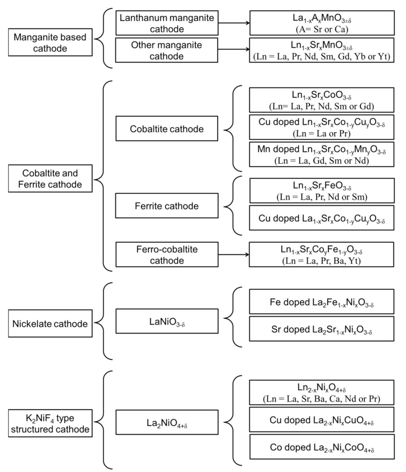
1.1. Different Classes of Perovskite-Based Cathode Materials for SOFC

Considering the high operating temperature and activation energy associated with the ORR on the cathode side of an SOFC, the choice of cathode is limited to platinum, gold, and silver [13]. However, noble materials are unsuitable for practical applications because of their high cost, poor compatibility with the electrolyte, and generation of a volatile oxide (POx) during high-temperature oxidation [14]. Therefore, perovskite-structured materials have been widely used as cathode materials in SOFCs. A list of various cathode materials used in SOFCs is presented in Figure 2. The most promising cathode for high-temperature SOFC is strontium-doped lanthanum manganite (LSM) [15]. However, the LSM cathode shows high polarization resistance at a reduced temperature because of its high activation energy for ORR, making it unsuitable for intermediate-temperature (IT) SOFCs below 800 °C [16]. Thus, alternative cathode materials for SOFCs operating at reduced temperatures have recently attracted considerable research attention.
Lanthanum strontium cobalt ferrite or La1−xSrxCo1.yFeyO3−δ (LSCF) perovskite has received a lot of attention due to its excellent chemical stability, high electrical conductivity, and high catalytic activity toward ORR [17]. LSCF cathodes have remarkably high oxygen diffusivities and oxygen surface exchange coefficients of 7.32 × 10⁻⁶ cm2/s and 1.5 × 10⁻³ cm/s, respectively, at 800 °C [18]. La0.6Sr0.4Co0.2Fe0.8O3−δ (LSCF6428) exhibits an excellent electronic conductivity of 330 S/cm and ionic conductivity of 0.008 S/cm at 600 °C [19]. LSCF is also an excellent electrocatalyst for ORR in various applications, including electrodes for solid-state electrochemical devices, oxygen sensors, and dense membranes for oxygen separation from air in coal gasification and oxy-fuel power plants [20]. Thus, LSCF can be used as a cathode for IT-SOFC applications.

1.2. Surface Composition-Performance Relationship of SOFC Cathodes

Compositional changes on the surface of the cathode plays an important role in accelerating the ORR rate at a reduced operating temperature [21]. Considering that the ORR rate is related to the cathode surface composition. It typically determines the cell efficiency at low temperatures [22], because at the cathode, the O2− ions must be transported to the cathode/electrolyte interface through the sufficiently porous structure (≈30%) to complete the first half of the electrochemical reaction [23]. This transport of O2− ions through the porous cathode must be continuous. However, any physical resistance to the transport of O2− ions through the cathode results in a voltage loss.
The change in the surface composition and its detrimental effect on the performance and stability of the SOFC cathode can be elucidated by in situ characterization during high-temperature cell operation. The composition and the structural, morphological, mechanical, optical, and electrical properties of an SOFC cathode can be analyzed using various techniques. Each technique can analyze the intrinsic and extrinsic properties of SOFC cathode materials. Mechanical analyses of the SOFC cathode are generally limited and not critical because of the porous structure of the cathode materials utilized, which are not used as freestanding support. Many new advanced techniques have been adopted, and researchers have extensively studied the microstructural distortion and gradual degradation of the electrochemical performance of energy materials [24].

1.3. Advanced Characterization of SOFC Cathdoe by Using Electron Spectroscopic Techniques

The use of an important analytical method on critically significant SOFC technology is certainly timely. Appropriate in situ measurements of elemental composition and chemical state of the SOFC cathode materials will be highly valuable towards improving its life expectancy and SOFC technology performance and stability. Therefore, to understand the complexity of the SOFC cathode degradation, researchers have developed new in situ and non-destructive experimental techniques to further explore the stability and degradation mechanism of SOFC cathode during fuel cell operation [25]. X-ray photoelectron spectroscopy (XPS) is one of the best tools for understanding compositional changes on the surface and at the interface of the SOFC cathode [26]. This technique can reveal the submicron-sized elements formed on the surface and at the cathode/electrolyte interface of the SOFC cathode [27]. Therefore, this paper reviews the use of XPS for studying the compositional changes on the surface and at the cathode/electrolyte interface of LSCF cathode materials because LSCF is one of the most commonly used cathode materials [28].
However, the low surface electrocatalytic activity for the ORR at reduced operating temperature and microstructural instability of the LSCF cathode are among the major concerns during SOFC operations. The segregation of Sr cation and subsequent reaction with CO2 and YSZ to form insulating-phase SrCO3 at the surface and SrZrO3 at the LSCF/YSZ interface can considerably affect the electrochemical performance of LSCF cathode materials [29,30]. Therefore, the microstructural changes and structural stability of the LSCF cathode should be determined. LSCF cathode degradation and XPS technique has been increasingly studied in the indexed literature [31,32,33,34]. This review paper aims to address how XPS is applied to SOFC cathode for understanding its degradation mechanism in absolute terms. The working principle, application, and limitations of XPS are also presented. To understand the fundamental behavior of the LSCF cathode under real fuel cell conditions, we determined its ORR mechanism and the microstructural degradation of the LSCF cathode. Finally, the strategies adopted to improve the structural stability and electrochemical performance of the LSCF cathode are discussed.

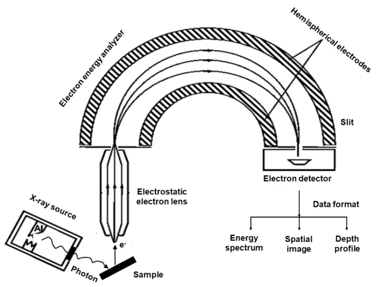
2. X-ray Photoelectron Spectroscopy (XPS)

XPS Principle and Experimental Details

XPS is a well-established and widely used surface-sensitive spectroscopic technique for studying the elemental composition of the surface of SOFC cathode layers within the first few nanometers [2]. This photoelectron spectroscopic technique is used to quantitatively analyze the surface electronic structure of crystalline solid through the photoelectron spectra. The basic principle of the photoelectron effect was explained by Albert Einstein in 1905. Kai Siegbahn constructed an XPS instrument that can analyze photoelectron emissions and allow the speciation analysis of the sample surface. In XPS, the sample is irradiated by a soft X-ray (typically 1–3 keV) source (AlKα or MgKα) with an energy of to ionize electrons from the surface, as shown in Figure 3. The photoelectron penetrates the samples between 1 nm and 10 nm, where the photon is absorbed by an atom in the solid, leading to ionization and emission of the core electron in different directions. The atom then releases energy by the emission of an Auger electron, in which the L electron falls to fill the core-level vacancy. The KLL Auger electron is then emitted to conserve energy released during initial emission. The photoelectric effect generates free electrons with certain kinetic energy ( E k i n ) and is measured by a detector.
The number of photoelectrons emitted as a function of their kinetic energy ( E k i n ) can be measured using an electron energy analyzer, and the corresponding photoelectron spectrum can be recorded. The XPS instrument measures the kinetic energy of all collected electrons. The photoelectron spectrum includes the photoelectron and Auger electron lines. Each element produces a characteristic set of peaks in the photoelectron spectrum at particular binding energy (EB) values that directly identify the element on the surface of the sample analyzed. The XPS records the core-level values of the elements in electronvolt (eV). The XPS spectral lines are identified by the shell (e.g., 1s, 2s, and 2p), from which the electrons are emitted.
Typical XPS spectra represent intensity versus EB, where the intensity area reveals the concentration and binding energy reveals the speciation. The spectrum reveals the electron energy distribution in the material. The position and height (intensity) of each peak in the photoelectron spectrum provide the desired information on the chemical state, elemental composition, empirical formula determination, electronic state, and oxidation state of the sample surface. These data are used to determine the binding energy of the ejected electron to obtain information about the electronic structure using the equation:
E B = h v E k i n Φ
where h is the Planck constant (6.63 × 10⁻³⁴ J s), ν is the frequency (Hz) of radiation, EB is the electron binding energy, Ekin is the kinetic energy of freed electrons, and Φ is the work function. Binding energy is an important parameter in the XPS analysis to obtain information about the electronic structure. The work function of the material is the difference between the Fermi level ( E F ) and the vacuum level ( E v a c ). For an electron to be ejected or emitted from the solid, the energy of the photoelectron must be sufficient to overcome its attraction to the material or Φ of the material. Table 1 represents the binding energy levels from the ejected electron and their corresponding orbital from which the electrons are ejected for selected elements.

3. Characterization of LSCF Cathodes by Using XPS

3.1. XPS for Surface Segregation or Enrichment of Sr on the Surface

XPS provides details on the chemical composition near the surface region and the oxidation state of each element from the binding energy of particular core levels. Therefore, a highly surface-sensitive technique such as in situ synchrotron-based XPS can be used to understand how Sr segregation accelerates the degradation mechanism of the LSCF cathode, and this method often limits the surface catalytic activity for the ORR [2]. Figure 4 shows the typical XPS spectra of the LSCF cathode in the region with La 3d, Sr 3d, Co 2p, Fe 2p, and O 1s peaks. Liu et al. investigated the performance degradation mechanism of LSCF and LSCF/GDC composite cathodes under different cathodic current polarizations by using XPS (Thermo VG Scientific Multilab 2000, East Grinstead, UK) [35]. The XPS spectra indicate that the La/Sr ratio increased to 1.36 from 0.61 (under open-circuit voltage) after being polarized at the cathodic current of 100 mA cm−2 at 750 °C for 120 h. Therefore, the surface segregation or enrichment of Sr is favorable under the cathodic current polarization of 100 mA cm−2, but the concentration decreased to 0.76 after the current polarization of 200 mA cm−2 for 120 h. This decrease in the concentration of Sr on the surface implies the incorporation of Sr into the LSCF lattice under high cathodic polarization treatment. However, the La/Sr ratio after current polarization treatment remains smaller than the stoichiometric ratio of 1.5 for LSCF.
Table 2 summarizes the binding energy levels for LSCF cathode under different cathodic polarization treatments. The values of binding energies agree well with the values of La, Sr, Fe, and Co in LSCF (Table 1). No preferential change was observed in the binding energy for La 3d and Fe 2p peaks [35]. Hence, the valence state does not change under cathodic polarization treatment. However, the binding energy of Sr increased to 132.45 eV after current polarization at 200 mA cm−2 for 120 h, indicating the existence of Sr on the surface [Figure 4 (Sr 3d)] [35].
Pan et al. [36] studied the effect of Sr surface segregation of LSCF electrode on its electrochemical performance by using XPS. Peak fitting on XPS spectra of Sr was conducted to confirm the surface segregation of Sr based second phase other than that of LSCF perovskite and compared the XPS spectra of raw LSCF powder, freshly pre-pared LSCF electrode, LSCF electrode after annealing for 24 h, and nitric acid-treated LSCF electrode after annealing (Figure 5). The 3d spectrum of Sr shows the coupling of 3d3/2 and 3d5/2 spin orbits, resulting in a doublet state. Peak fitting of Sr 3d spectrum resulted in the extraction of two pairs of Sr 3d3/2 and Sr 3d5/2 spin orbits. The pair with lower binding energy was denoted by SrB, which is located in bulk bound Sr, while Sr denotes the pair with higher binding energy present on the surface of the LSCF electrode.

3.2. XPS for Element Migration of Sr and Co

The XPS analysis shows that the atomic concentration of Co cation on the surface of LSCF increased from 6.91 (under OCV) to 9.93 after current polarization at 200 mA cm−2 for 120 h (Figure 4 [Co 2p])). This result indicates that cathodic current polarization promotes the migration of Co to the LSCF surface. This finding is consistent with the considerable decrease in the binding energy for the Co 2p peak for LSCF after cathode polarization resistance (Table 2). This phenomenon indicates the change in the oxidation state of Co from Co2+ to Co3+. Moreover, the performance degradation rate of the LSCF is higher in the high current density of 500 mA cm−2 at 750 °C than that in the lower current density. This result could be attributed to the accelerated migration of Sr and Co cations to the LSCF surface under high cathodic current polarization conditions, leading to the formation of the insulating SrCoOx phase [37].
Ha et al. [38] performed XPS of LSCF and 3DOM-LSCF (three-dimensionally ordered microporous LSCF) and found that both Co and Fe show two coexisting oxidation states (Figure 6). The B-site in the perovskite is occupied by Fe or Co in either 2+ or 3+ oxidation states. Furthermore, peak fitting for Fe 2p orbital was conducted within Fe2+ and Fe3+ component constraints and their respective satellites. The higher binding energy of iron denotes Fe3+ (Figure 6b). In addition, Co2+, Co3+, and their respective satellites were used to fit the Co 2p region. However, in this case, the higher binding energy is attributed to Co2+. The oxygen XPS spectra are shown in Figure 6c, which depict the lattice, surface, and adsorbed oxygen with increasing binding energy, respectively.
Bucher et al. [39] examined the degradation behavior of the LSCF cathode as a function of water vapor and found the segregation and migration of Sr to a depth of greater than 150 nm and the formation of SrCrO4 and Cr2O3 species via the reaction with SrO on the cathode surface. Pan et al. [36] also studied the relationship between the performance degradation and compositional changes on the surface of the LSCF cathode by using electrochemical impedance spectroscopy (EIS) and XPS, respectively. The XPS analysis showed that the aged LSCF cathode exhibited significant segregation of Sr concentration and formation of SrO layer on the surface after the LSCF cathode was treated at elevated temperature (750 °C) for 24 h, thus remarkably decreasing the performance degradation as shown (Figure 7a) [36]. Figure 7a shows that the polarization resistance (RP) increases gradually, indicating the performance degradation of the LSCF cathode. Therefore, the degradation of the LSCF cathode is caused by the segregated Sr and the formation of the SrO layer on the surface, thus remarkably changing the composition at the surface.
Vovk et al. [32] employed in situ XPS and reported a 5% increase in the Sr/(La + Co) ratio on the surface of the LSC thin-film after cathodic polarization. Mutoro et al. [40] also observed a threefold increase in the Sr 3d intensity and a decrease in the La 4d and Co 3p intensities upon heating the surface of the LSC thin film from 25 °C to 650 °C by using in situ synchrotron-based XPS. Therefore, Sr segregation or migration is favored during high-temperature treatment (Figure 8). Yu et al. examined the effect of Sr content on the Sr segregation and diffusion phenomena by using hard X-ray photoelectron spectroscopy and observed rich SrCO3 phase on the LSCF surface when the Sr content is increased [41].
The relationship between the extent of Sr surface segregation and the Sr content was successfully identified using surface-sensitive XPS analysis. Wang et al. [42] studied the LSCF symmetrical cell by using XPS (Thermo Scientific ESCALAB 205Xi, East Grinstead, UK) and observed a slight increase in the low-energy satellite peak of Sr 3d at 131.8 eV after heat treatment at 800 °C. Liu et al. [43] used XPS (Thermo VG Scientific Multilab 2000, East Grinstead, UK) and found that the Co concentration on the surface of the LSCF–Gd-doped ceria composite cathode increased from 10.66% to 19.65% (atomic percentage of cobalt) after cathodic polarization for 500 h at 750 °C. The XPS results reveal a correlation between the segregation and structural instability of LSCF cathodes.
XPS sputter depth profiling is also widely used to obtain elemental and composition information as a function of depth within layer and layer interfaces. DiGiuseppe et al. [31] used the depth profile capability of XPS to study the interfaces of the LSCF cathode up to a depth of approximately 50 µm after electrochemical testing [Figure 4iv] and detected Sr migration into the ceria barrier layer via surface diffusion. However, the Sr 3d peak does not change or shift with increasing depth. Therefore, no change occurred in the Sr chemical state and lack of formation of new compounds. Liu et al. [44] also investigated the migration of Sr and Co in LSCF after different cathodic polarization treatments at different depths by using XPS (Thermo VG Scientific Multilab 2000, East Grinstead, UK) and found that cathode polarization at 200 mA cm−2 promotes the migration of Sr and Co from the top surface to the bulk of the LSCF. This migration is responsible for suppressing the Sr surface segregation and performance activation of the LSCF cathode. The profile depth was set to 5–15 nm by eroding the LSCF surface through ion etching by using an argon beam with a diameter of 50 μm. Table 3 shows the Sr/La and Co/Fe ratio at different depths, and these values were calculated using the element ratios of the XPS pattern.
All Sr/La ratios after current polarization treatment (Sr/La = 0.67) are larger than the stoichiometric value of the LSCF, indicating the migration of Sr from the surface to the bulk of the LSCF cathode. After the current polarization treatment of 100 mA cm−2, the Sr/La ratio was four times higher than that of the LSCF before treatment, demonstrating the severe surface segregation of Sr. At high cathodic polarization (200 mA cm−2), the Sr/La ratios are lower than those of LSCF after 100 mA cm−2 treatment, demonstrating the diffusion of Sr from the surface into the bulk LSCF lattice. Hence, high cathodic polarization suppresses the formation of SrO on the surface of the LSCF cathode, resulting in improved ORR rate or low cathode polarization resistance. After cathodic polarization treatment, the Co/Fe ratios of the LSCF are lower than those of the untreated LSCF cathode, indicating the migration of Co from the surface to the bulk of the LSCF cathode. However, the migration of Sr and Co from the surface to the bulk of the LSCF cathode may weaken the mechanical stability by accommodating a substantial amount of oxygen vacancies in the LSCF structure [44].
Knöfel et al. [34] employed X-ray powder diffraction (XRD) and XPS to investigate the surface chemistry and phase stability of LSM/YSZ composite cathode under different fuel cell conditions. They observed that the degradation of LSM/YSZ composite cathode strongly depends on humidity, oxygen partial pressure, and heat treatment. The XRD results indicate the formation of secondary phases, such as strontium zirconate and lanthanum zirconate, at the LSM/YSZ interface caused by the surface diffusion and interaction of Sr and La with YSZ. This phenomenon is related to the increased concentration of Sr on the surface of the perovskite cathode, as confirmed by XPS analysis. Based on the ex-situ XPS analysis, the concentration of Sr cation on the surface increased, and this metal exists in the form of strontium carbonate or strontium hydroxide, which corresponds to high binding energy (133.3 eV). Monoclinic zirconia oxide (m-ZrO2) formed at the LSM/YSZ interface, indicating the activated inter-diffusion of Mn into YSZ at high temperatures.
These microstructural and compositional changes in the LSCF cathode could remarkably alter the electrochemical performance of the single cells. This phenomenon is possible because the electrochemical reactions for symmetrical cells with LSCF cathode consist of three physicochemical processes as follows: (1) electrolyte ohmic resistance, (2) charge transfer process associated with incorporation of O2− ion at the cathode/electrolyte interface and electronic transfer at the interconnect/cathode interface, and (3) oxygen dissociation/adsorption on the cathode surface [45]. These processes occur at different times during charge transportation. The response time for electrolyte ohmic resistance is approximately zero [46]. EIS can be employed to analyze the above-mentioned rate-limiting steps in the cathode material. EIS can effectively characterize various electrochemical steps and simultaneously monitor electric and dielectric phenomena in the cathode material. The interfacial polarization resistance in the LSCF cathode was measured by applying constant-amplitude AC voltage over a predefined frequency on the symmetrical cell being investigated. The phase shift and amplitude of the resulting current response were measured as a function of frequency. If various rate-limiting steps occur at different frequencies, then the sum of all individual reaction steps represents the overall cathode reaction. The electrochemical reaction of cathode materials was measured using ASR, which is obtained via EIS analysis and was used to characterize the cathode symmetrical cell. A typical impedance spectrum of a cathode symmetrical cell at 800 °C is shown in Figure 9.
The interfacial polarization resistance in the LSCF cathode is associated with two processes, namely, oxygen molecule diffusion through the porous structure and charge transfer to reduce the oxygen molecules into oxide ions at the cathode/electrolyte interface [47]. The presence of two arcs in the impedance spectra indicates the two electrode processes (R2 and R3) during the ORR [48]. The impedance spectra were fitted with the equivalent circuit to investigate the rate-limiting steps in cathodes (Figure 9, inset). In the above-mentioned circuit, L is the inductance, R1 is the electrolyte ohmic resistance, R2 is the high-frequency arc that can be related to the charge transfer process associated with the incorporation of O2− ions at the cathode/electrolyte interface, R3 is the low-frequency arc associated with oxygen dissociation/adsorption on the cathode surface, and CPE is the constant-phase element [49]. In general, low capacitance ranging from 10−12 F to 10−6 F is associated with electrolyte resistivity (bulk and grain boundary resistance), whereas high capacitance of >10−5 F is associated with electrode resistivity arc [50]. The CPE in the equivalent circuit can be expressed as follows [51]:
Z CPE = 1 / Q   ( j ω ) n
where ω = 2·π·(f is the frequency), Q is the pseudocapacitance, j is equal to 1 , and n is the empirical constant value between 0 and 1. The actual capacitance value can be calculated using Equation (3), as follows [24]:
C = R p ( 1 n ) / n   Q ( 1 / n )
Mid- and low-frequency arcs for MIEC cathode materials can be attributed to the electrode process. LSCF cathodes can provide active sites for the ORR on the surface to the TPB and pathway for the incorporation/diffusion of O2− ions through the bulk and at the cathode/electrolyte interface [52,53]. The overall ASR was calculated using the equation ASR = ( R p × A ) / 2 , where A is the active area. The sum of the high- and low-frequency intercepts is the total interfacial or cathode polarization resistance (Rp = R2 + R3) of the symmetrical cell [54]. The interfacial polarization resistance of the LSCF cathode decreases gradually with increasing temperature.

4. Performance and Degradation Mechanism of LSCF Cathodes

4.1. Microstructural Degradation of the LSCF Cathode

The performance and long-term structural stability of the LSCF cathode under various SOFC operational conditions have been extensively studied [55]. Figure 10 shows the segregation of Sr cation and formation of insulating phase SrZrO3 at the LSCF/YSZ interface as a function of polarization time at 100 mA cm−2 and operating temperature of 750 °C [56]. This electrically insulating Sr-rich layer de-activates the oxygen diffusion kinetics and blocks the migration of oxygen ions at the cathode/electrolyte interface, thus affecting the electrical conductivities of the LSCF cathode [57,58]. It also alters the thermal expansion coefficient of the cathode/electrolyte layers, thereby affecting the mechanical stability of the interface [59]. This segregation or enrichment of cations is caused by the mismatch of the ionic radii between the dopant Sr2+ (1.44 Ǻ) and the host La3+ (1.36 Ǻ) [36,60]. Moreover, the electrostatic attraction between these ions produces a strong Columbic attraction that drives the dopant cations to the positively charged interface and causes the dopant Sr2+ cation to segregate toward the surface. At the LSCF surface, the concentration of Sr cations increases with the decrease in partial oxygen pressure and increasing operating temperature [61].
The segregation of cations, reactivity with YSZ, and deposition of SrO at the YSZ surface and the LSCF/YSZ interface has been studied as functions of oxygen partial pressure, air humidity, gas composition, temperature, and electrochemical polarization treatment [41,56]. Chen et al. [28,62] investigated Sr segregation and chemical reaction between deposited SrO and YSZ behavior under different cathodic polarization treatments at temperatures above 750 °C. The polarization treatment favored Sr segregation and diffusion to form an oxygen ion-blocking layer (SrZrO3 phase) in the LSCF/YSZ interface region. Under cathodic conditions, the segregation or enrichment of strontium (Equation (4)) and cobalt (Equation (5)) on the surface, the formation of SrZrO3 phase by reacting with yttria-stabilized zirconia (YSZ) electrolyte (Equation (6)), and the reactivity with chromium and contaminates (e.g., boron) (Equation (8)) can cause rapid deterioration of ORR kinetics and surface instability of LSCF-based cathode materials [37]. Under elevated operating temperatures, the segregation and/or structural distortion on the surface is enhanced, affecting the adsorption/desorption kinetics of the cathode.
La 0.6 Sr 0.4 Co 0.2 Fe 0.8 O 3 cathodic   poloarization ,   750   ° C   La 0.6 Sr 0.4 x Co 0.2 Fe 0.8 O 3 + x SrO s
La 0.6 Sr 0.4 Co 0.2 Fe 0.8 O 3 cathodic   poloarization ,   750   ° C La 0.6 Sr 0.4 Co 0.2 y Fe 0.8 O 3 + y CoO
x SrO s + Y 0.08 Zr 0.92 O 2 Δ Sr ZrO 3 + Y 2 O 3
CrO 3 + SrO SrCrO 4
La 0.6 Sr 0.4 Co 0.2 Fe 0.8 O 3 + CoO + B 2 O 3 LaBO 3 + Fe 2 O 3

4.2. Compositional Changes in LSCF Cathode

The compositional change at the surface and bulk of the LSCF can be observed during the SOFC operating conditions. Hashimoto et al. [63] utilized atmospheric controlled high-temperature X-ray diffraction technique to study the thermo-chemical stability of cobalt-rich cathode material. They found that La0.6Sr0.2Co0.8Fe0.2O3−δ decomposed completely into (La,Sr)2(Co,Fe)O4 and a CoO phase (halite) at relatively high oxygen partial pressure (ca. PO2 10−6 bar at 800 °C). Wang et al. performed the elemental analysis of the LSCF cathode by using EDX and secondary-ion mass spectrometry; they found that the segregated Sr cation migrated to the YSZ electrolyte layer and reacted to form insulating SrZrO3 phase [64]. Ali et al. [65] employed field emission scanning electron microscopy (FESEM) coupled with EDX to investigate the microstructural stability and long-term performance degradation of the LSCF current-collecting layer cathode at 600 °C for over 100 h (Figure 11b,c); the Sr concentration on the surface increases from 7.4% to 10.3%. Moreover, the electrochemical polarization resistance increases gradually especially in the low-frequency region, where resistance is associated with the dissociation/adsorption of oxygen molecules and diffusion on the LSCF cathode surface (Figure 11a) [48]. The FESEM image shows substantial changes in the morphology and Sr segregation on the LSCF layer, which may be the main reason for the degradation of the performance of the LSCF cathode [65]. However, EDX provides a bulk Sr concentration and limited information about the speciation or oxidation state of each element in the samples.
The properties and reactivity of the surface depend on the bonding geometry of molecules to the surface, chemical composition, chemical structure, physical topography, atomic structure, and electronic state [66]. Various electron spectroscopic techniques have been employed to investigate all these properties and provide chemical information about the oxidation state and elemental composition of the surface of any solid substrate [67]. Surface-based spectroscopy is routinely used to obtain information on compositional changes near the surface region of the LSCF cathode; examples of this technique include XPS, ultraviolet photoelectron spectroscopy, Auger electron spectroscopy (AES), electron energy loss spectroscopy (EELS), reflected EELS, and high-resolution EELS. The long-term stability issues such as the Sr segregation and diffusion, formation of Sr-rich layer, and presence of secondary phases, such as SrZrO3 and SrCrO4 at the LSCF/YSZ interface region during the SOFC operation, which can accelerate the deterioration of the ORR and affect the electrochemical performance [41]. Thus, understanding the compositional changes associated with the segregation or enrichment of cations at the surface of the LSCF cathode is crucial. Thus, a characterization tool with high surface sensitivity must be utilized to understand the degradation mechanism in SOFC cathode materials.

5. Strategies to Suppress Sr Surface Segregation

As discussed in this review, XPS analysis is a promising technique to analyze the correlation between the segregation and performance degradation of the LSCF cathode material. Therefore, Sr segregation or enrichment of Sr on the surface of the LSCF significantly affects the compositional stability and subsequently causes detrimental effects on the surface property of the LSCF cathode because Sr is an extremely active compound in LSCF and can easily diffuse through the porous structure of the cathode material during high-temperature sintering and under cathodic polarization conditions. Therefore, Sr segregation is an inherent property of the LSCF cathode material, and it has been generally observed and unavoidable. Although the segregation of Sr cations cannot be prevented, it can be reduced via surface enhancement and the use of innovative nanostructured architecture through wet impregnation or infiltration. To increase the lifetime of an LSCF cathode, scholars must investigate its degradation mechanism under different operational conditions. Current research focuses on modifications on the cathode material, reaction barrier layer, and the interface between these two to improve the SOFC reliability and performance.
Electrochemical polarization and fuel cell operating conditions significantly contribute to the formation of SrO and the migration of Sr cations to form an oxygen ion-blocking layer (SrZrO3 phase) at the cathode/electrolyte interface. Considerable efforts have been made to avoid surface segregation and interaction between the LSCF and YSZ to improve long-term structural stability and electrocatalytic activity for ORR. A dense barrier layer of the doped ceria-based electrolyte between LSCF and YSZ can be used to minimize the reaction between segregated Sr and YSZ under the cathodic polarization treatment (Figure 12). However, this approach cannot completely eliminate the formation of the resistive SrZrO3 phase at the LSCF layer and at the doped ceria/YSZ interface (Figure 12) because of the presence of an open porosity and the subsequent densification with the ceria-based interlayers at low sintering temperatures. In general, the GDC interlayer at the top of the pre-sintered YSZ electrolyte must be sintered below ~1200 °C to prevent GDC and YSZ from forming high-temperature chemical reactions. Densifying the interlayer at low sintering temperatures seems impossible because of the refractory aspect of ceria. However, this open porosity in the interlayers must be reduced to prevent the formation of an undesired chemical substance at the interlayer and the cathode/electrolyte interface and to restrict the Sr cation migration from the cathode to the zirconia-based electrolyte materials [68,69].
Numerous alternate deposition methods have been identified as important achievements for achieving a dense diffusion barrier interlayer, such as atomic layer deposition, PLD, MS, and chemical solution deposition. However, the cost of production to scale up the SOFC technology by using these approaches remains uncertain. The densification of the LSCF cathode is one of the important strategies to mitigate the migration of cations from the cathode to the interlayer/electrolyte interface layers. De Vero et al. [71] recently reported on the improved stability of the SOFCs by adopting a dense LSCF layer between the cathode–GDC interlayer interfaces. The thin and dense LSCF film prepared by the PLD between the porous LSCF cathode and the GDC interlayer effectively reduced the degradation process associated with the Sr cation migration. Fan et al. [72] stated that the LSCF cathode deteriorated less with an SDC interlayer between the electrolyte and the cathode using carbon-containing suspension plasma spray deposition along with lanthanum chromite coating. Uhlenbruck et al. [73] showed how CGO thin films formed a coat between the cathode and the electrolyte using physical vapor deposition (PVD), prevented the diffusion of strontium from the cathode, resulted in improved SOFC efficiency, and were more effective than screen-printed coatings. Roeder et al. [74] provided another method to improve degradation by modifying the LSCF cathode through atomic layer deposition with Group IVA oxides and cobalt-based compositions. These mitigating measures revealed that the segregated Sr migration is considerably suppressed from the LSCF to the GDC interlayer, thereby limiting the rapid formation of SrZrO3 after long-term activity. Therefore, the modification of electrode/interlayer/electrolyte layers can successfully reduce the interface resistance and consequently improve the cell efficiency and stability.
The stress/strain minimization of the surrounding lattice and electrostatic or charged interactions of the dopants is known as the main motivating factor for the isolation of Sr dopant cations to the surface of the LSCF cathode. This is attributed to the ionic radii imbalance between the dopant Sr2+ and host La3+ cations. However, this degradation mechanism in the LSCF cathode can be reduced or prevented via the surface modification through the doping of the high-valence element infiltration technique and adopting a nanostructured architecture using the wet impregnation or infiltration technique. Ding et al. [30] used the first principles density functional theory (DFT) computational method to locate and suppress Sr segregation in the LSCF cathode. Their study identified two thermodynamic driving forces (strain and surface charge) for Sr segregation and suggested to apply compressive strain and to reduce surface charge (reducing the concentration of surface oxygen vacancies) to reduce the Sr segregation. The compressive strain can be applied by the doping of larger elements and/or surface coating with catalytically active LSM phases in a porous LSCF substrate. The formation of excess oxygen vacancies on the surface can be reduced by doping high-valence elements in the Sr and B-site or low-valence elements in the La-site in order to suppress the Sr surface segregation.
Lynch et al. [75] modified the surface of LSCF cathode with a dense thin LSM surface coating by a solution infiltration process and tested at 700 °C under fuel cell operating conditions. The electrochemical performance showed that the cell with the LSM-infiltrated LSCF cathode exhibited improved stability toward Sr segregation with reduced interfacial polarization resistance. Giuliano et al. [76] also reported the beneficial effect of the LSM infiltration on the long-term stability and electrochemical performance of the LSCF cathode. This result suggests that the presence of the LSM thin layer on the LSCF backbone can inhibit the Sr segregation and increase the oxygen vacancy concentration when the cathodic overpotential is applied. This finding indicates the absence of an activation energy barrier for the oxygen dissociation/adsorption on the cathode surface, i.e., an increase in the oxygen exchange surface activity, and thus leads to the enhanced electrocatalytic activity for ORR [76]. Similar enhancement by the infiltration of a catalytic active phase on the electrocatalytic activity and the compositional stability of the LSCF cathode was also reported on La0.8Sr0.2FeO3−δ [77], Sm0.5Sr0.5CoO3−δ [78], La2NiO4+δ [79], Pr1−xSrxMnO3 [80], La1−xSrxCoO3−δ, and La1.97Sr0.03Zr2O7 [81]. The infiltration or wet impregnation of catalytic active components into the LSCF backbone can also be carried out using a wet powder spray coating [82] and an inkjet printing technique [83].
Doping with high-valence cations such as Nb+5, Sb+5, Mo+6, Ta+5, and Y+3 in the B-site is an effective strategy to stabilize the phase structure and the compositional changes of Sr-containing perovskite cathode materials. These large-sized cations tend to suppress the Sr segregation on the LSCF cathode surface by reducing the surface oxygen vacancies and influencing the ionic conductivity of the perovskite material [84]. Chen et al. [85] studied the effects of Nb cations at the B-site on the stability and electrochemical performance of LSCF-based cathode materials and observed remarkable improvement on the structural stability, leading to the minimized surface segregation of Sr cations. This high-valence addition of Nb5+ cations could reduce the valence state of the B-site cations and thus expand the LSCF lattice, which in turn can accommodate the large Sr2+ cations and thereby reduce the Sr segregation. This finding indicates that the introduced Nb dopant enhances the valence stability of the Co and Fe cations at the B-site, thus increasing the energy barrier and preventing the formation of excess oxygen vacancies at the surface. However, Nb doping exhibited a detrimental effect on the electrochemical activity of the LSCF cathode [86]. Dual doping of Nb and Pd into the B-site of the LSCF cathode can enhance the structural stability and the electrochemical performance because of the presence of highly active Pd nanoparticles in the LSCF structure that promote the ORR kinetics [86]. Figure 13 summarizes the factors influencing the cation migration in LSCF-based cathode materials and strategies to develop promising LSCF-based cathode materials for SOFCs and SOECs.

6. Concluding Remarks

The XPS, a powerful surface-sensitive technique for surface analysis, can be used to identify the elemental composition and chemical or oxidation state of samples near the surface region (1–10 nm). It has a wide range of applications, such as corrosion and failure analyses, and is a standard tool for surface material characterization from cookware coating to thin-film electronic and polymer surfaces. However, XPS has some limitations. It is very expensive, cannot detect hydrogen and helium, and has a slow processing time. For solid oxide fuel cells, XPS cannot profile the material in-depth as it is a surface technique. The active area of a porous LSCF cathode is best described as a buried interface with an extend of a few µm. XPS is a surface technique with a few nanometers of analysis depth and is therefore unsuitable for characterizing such systems. Furthermore, when characterizing LSCF cathodes using XPS, LSCF cathodes do not show electrochemical activity everywhere, but only in a localized zone (called the utilization length λ) close to the cathode/electrolyte interface. Typically, the value of the utilization depth is estimated to be around 5–20 μm for LSCF, depending on the operation conditions. As a result, researchers should proceed with extreme caution when reading the experimental details of research claiming to establish correlations between the chemical state at the (electrochemically inactive) surface of a porous LSCF cathode and the polarization resistance. Moreover, XPS requires a very high vacuum during analysis, meaning in situ characterization of SOFC is impossible using this technique.
Recent developments in XPS enable the measurement of the uniformity of elemental composition as a function of depth by ion beam etching or depth profiling. Angle-resolved XPS (ARXPS) also opens up new possibilities for measuring elemental composition as a function of depth by changing the sample tilt angle with reference to the analyzer. Unlike depth profiling XPS, ARXPS can carry out such measurements and in-depth analysis without ion beam sputtering. Furthermore, ARXPS is a non-destructive technique that measures the uniformity of elemental composition near-surface regions. The XPS is now available in ultra-high resolution for imaging and elemental analyses with spatial resolutions of as low as 70–100 nm. Spatially resolved XPS can analyze the full material at the nanoscale by adding high spatial resolution and imaging capabilities to XPS.
Near-ambient pressure XPS (NAP-XPS) is a relatively recent breakthrough that simplifies the investigation of SOFC materials. NAP-XPS is a less common method of XPS analysis that allows for the analysis of samples under realistic conditions at relatively high pressures (i.e., >2500 Pa). As a result, NAP-XPS does not require ultra-high vacuum (UHV) conditions in the analysis region because the sample is surrounded by a gas environment during the experiment. As a result, a wide range of samples, including insulating samples, biological samples, gases, liquids, and their interfaces, can be studied easily. When performing XPS measurements in a gaseous environment, the photoelectrons emitted by the samples are dispersed by collisions with the surrounding gas molecules before entering the hemispherical electron analyzer.
Given the development and implementation of photoelectron spectromicroscopy, the surface chemistry of the sample can be analyzed by full-field or scanning methods. The XPS has been widely used to study the degradation mechanism of SOFC cathode materials, which often affect the electrical performance and mechanical stability under cathodic polarization.
The LSCF cathode is one of the most popular and extensively studied materials for SOFC applications. However, scholars must investigate the degradation mechanisms of this material under different operational conditions to create an understanding of how to increase the lifetime of the LSCF cathode. Electrochemical polarization and fuel cell operating conditions significantly contribute to the formation of SrO and the migration of Sr cation to form an oxygen ion-blocking layer (SrZrO3 phase) at the cathode/electrolyte interface. Considerable efforts have been made to avoid surface segregation and interaction between the LSCF and YSZ to improve structural stability and electrocatalytic activity for ORR. A dense barrier layer of doped ceria-based electrolyte between LSCF and YSZ can be used to minimize the reaction between segregated Sr and YSZ under cathodic polarization treatment. However, this approach will not completely eliminate the formation of the resistive SrZrO3 phase at the LSCF layer and the doped ceria/YSZ interface. Applying compressive strain by surface coating with LSM material and reducing surface charge by doping with higher-valence elements in the Sr and B-site can minimize or prevent Sr surface segregation and enhance the structural stability and electrochemical polarization performance. Information about the surface property or surface chemistry of perovskite-type cathode materials is important because of differences between the chemistry of the surface and the bulk. Since XPS is a surface-sensitive characterization technique and only reveals the surface properties of the sample, it can be used to examine Sr and Co segregation on the surface of the LSCF cathode as a function of temperature, oxygen partial pressure, and electrochemical polarization to understand the potential degradation mechanism associated with the LSCF cathode. Thus, XPS technology enables new possibilities and opportunities for researchers to elucidate the degradation behavior of the perovskite cathode region (1–10 nm) near the surface.

Author Contributions

Conceptualization, writing–review and editing, M.A.; writing-original draft preparation, writing–review and editing, project administration, funding acquisition, M.A.S.A.; writing–review and editing, U.M.K. and M.H.; conceptualization validation and formal analysis, A.H.K.; supervision, project administration, A.M. All authors have read and agreed to the published version of the manuscript.

Funding

This research was funded by Universiti Kebangsaan Malaysia (UKM) through the research grant: GGPM-2021-058.

Institutional Review Board Statement

Not applicable.

Informed Consent Statement

Not applicable.

Data Availability Statement

Not applicable.

Conflicts of Interest

The authors declare no conflict of interest.

References

  1. Baldinelli, A.; Barelli, L.; Bidini, G.; Bonucci, F.; Iskenderoğlu, F.C. Regarding Solid Oxide Fuel Cells simulation through artificial intelligence: A neural networks application. Appl. Sci. 2018, 9, 51. [Google Scholar] [CrossRef] [Green Version]
  2. Singh, S.; Pandey, R.; Presto, S.; Carpanese, M.P.; Barbucci, A.; Viviani, M.; Singh, P. Suitability of Sm3+-Substituted SrTiO3 as anode materials for solid oxide fuel cells: A correlation between structural and electrical properties. Energies 2019, 12, 4042. [Google Scholar] [CrossRef] [Green Version]
  3. Woo, S.H.; Song, K.E.; Baek, S.-W.; Kang, H.; Choi, W.; Shin, T.H.; Park, J.-Y.; Kim, J.H. Pr- and Sm-Substituted Layered Perovskite Oxide Systems for IT-SOFC Cathodes. Energies 2021, 14, 6739. [Google Scholar] [CrossRef]
  4. Bianchi, F.R.; Bosio, B.; Baldinelli, A.; Barelli, L. Optimization of a reference kinetic model for solid oxide fuel cells. Catalysts 2020, 10, 104. [Google Scholar] [CrossRef] [Green Version]
  5. Mendonça, C.; Ferreira, A.; Santos, D.M.F. Towards the Commercialization of Solid Oxide Fuel Cells: Recent Advances in Materials and Integration Strategies. Fuels 2021, 2, 23. [Google Scholar] [CrossRef]
  6. Sivasankaran, V.; Combemale, L.; François, M.; Caboche, G. Ce0.9Gd0.1O2−x for intermediate temperature solid oxide fuel cells: Influence of cathode thickness and anode functional layer on performance. Energies 2020, 13, 4400. [Google Scholar] [CrossRef]
  7. Anwar, M.; Muhammed Ali, S.A.; Baharuddin, N.A.; Raduwan, N.F.; Muchtar, A.; Somalu, M.R. Structural, optical and electrical properties of Ce0.8Sm0.2−xErxO2−δ (x = 0–0.2) Co-doped ceria electrolytes. Ceram. Int. 2018, 44, 13639–13648. [Google Scholar] [CrossRef]
  8. Guk, E.; Ranaweera, M.; Venkatesan, V.; Kim, J.-S. Performance and Durability of Thin Film Thermocouple Array on a Porous Electrode. Sensors 2016, 16, 1329. [Google Scholar] [CrossRef] [Green Version]
  9. Tu, Z.; Tian, Y.; Liu, M.; Jin, B.; Akbar, M.; Mushtaq, N.; Wang, X.; Dong, W.; Wang, B.; Xia, C. Remarkable Ionic Conductivity in a LZO-SDC Composite for Low-Temperature Solid Oxide Fuel Cells. Nanomaterials 2021, 11, 2277. [Google Scholar] [CrossRef]
  10. Li, S.; Zhan, C.; Yang, Y. Control System Based on Anode Offgas Recycle for Solid Oxide Fuel Cell System. Math. Probl. Eng. 2018, 2018, 4198954. [Google Scholar] [CrossRef] [Green Version]
  11. Wachsman, E.D.; Lee, K.T. Lowering the temperature of solid oxide fuel cells. Science 2011, 334, 935–939. [Google Scholar] [CrossRef]
  12. Su, S.; Gao, X.; Zhang, Q.; Kong, W.; Chen, D. Anode-Versus Cathode-Supported Solid Oxide Fuel Cell: Effect of Cell Design on the Stack Performance. Int. J. Electrochem. Sci. 2015, 10, 2487–2503. [Google Scholar]
  13. Jiao, R.; Zhang, W.; Sun, H.; Zhu, Z.; Yang, Z.; Liang, W.; Li, A. N- and S-doped nanoporous carbon framework derived from conjugated microporous polymers incorporation with ionic liquids for efficient oxygen reduction reaction. Mater. Today Energy 2020, 16, 100382. [Google Scholar] [CrossRef]
  14. Li, Y.; Gemmen, R.; Liu, X. Oxygen reduction and transportation mechanisms in solid oxide fuel cell cathodes. J. Power Sources 2010, 195, 3345–3358. [Google Scholar] [CrossRef]
  15. Silva, C.L.S.; Gama, L.M.; dos Santos, J.A.F.; Paes, H.R., Jr.; Domingues, R.Z.; Rangel, M.d.C. Effect of La0.8Sr0.2MnO3 powder addition in the precursor solution on the properties of cathode films deposited by spray pyrolysis. Rev. Matér. 2017, 22, 1–10. [Google Scholar]
  16. Kim, J.-H.; Manthiram, A. Layered LnBaCo2O5+δ perovskite cathodes for solid oxide fuel cells: An overview and perspective. J. Mater. Chem. A 2015, 3, 24195–24210. [Google Scholar] [CrossRef]
  17. Hu, B.; Wang, Y.; Xia, C. Effects of Ceria Conductivity on the Oxygen Incorporation at the LSCF-SDC-Gas Three-Phase Boundary. J. Electrochem. Soc. 2015, 162, F33–F39. [Google Scholar] [CrossRef]
  18. Almar, L.; Szász, J.; Weber, A.; Ivers-Tiffée, E. Oxygen Transport Kinetics of Mixed Ionic-Electronic Conductors by Coupling Focused Ion Beam Tomography and Electrochemical Impedance Spectroscopy. J. Electrochem. Soc. 2017, 164, F289–F297. [Google Scholar] [CrossRef] [Green Version]
  19. Sun, C.; Hui, R.; Roller, J. Cathode materials for solid oxide fuel cells: A review. J. Solid State Electrochem. 2010, 14, 1125–1144. [Google Scholar] [CrossRef]
  20. Guo, S.; Wu, H.; Puleo, F.; Liotta, L. B-Site Metal (Pd, Pt, Ag, Cu, Zn, Ni) Promoted La1−xSrxCo1−yFeyO3–δ Perovskite Oxides as Cathodes for IT-SOFCs. Catalysts 2015, 5, 366–391. [Google Scholar] [CrossRef] [Green Version]
  21. Burnwal, S.K.; Bharadwaj, S.; Kistaiah, P. Review on MIEC Cathode Materials for Solid Oxide Fuel Cells. J. Mol. Eng. Mater. 2016, 4, 1630001. [Google Scholar] [CrossRef]
  22. Zamudio-García, J.; Albarrán-Aroca, N.; Porras-Vázquez, J.M.; Losilla, E.R.; Marrero-López, D. Influence of Bi1.5Y0.5O3 Active Layer on the Performance of Nanostructured La0.8Sr0.2MnO3 Cathode. Appl. Nano 2020, 1, 14–24. [Google Scholar] [CrossRef]
  23. Muhammed Ali, S.A.; Raharjo, J.; Anwar, M.; Khaerudini, D.S.; Muchtar, A.; Spiridigliozzi, L.; Somalu, M.R. Carbonate-based lanthanum strontium cobalt ferrite (LSCF)-samarium-doped ceria (SDC) composite cathode for low-temperature solid oxide fuel cells. Appl. Sci. 2020, 10, 3761. [Google Scholar]
  24. Pérez-Flores, J.C.; Castro-García, M.; Crespo-Muñoz, V.; Valera-Jiménez, J.F.; García-Alvarado, F.; Canales-Vázquez, J. Analysis of Performance Losses and Degradation Mechanism in Porous La2−X NiTiO6−δ:YSZ Electrodes. Materials 2021, 14, 2819. [Google Scholar] [CrossRef]
  25. Yan, D.; Zhang, C.; Liang, L.; Li, K.; Jia, L.; Pu, J.; Jian, L.; Li, X.; Zhang, T. Degradation analysis and durability improvement for SOFC 1-cell stack. Appl. Energy 2016, 175, 414–420. [Google Scholar] [CrossRef]
  26. Van der Heide, P. X-ray Photoelectron Spectroscopy: An Introduction to Principles and Practices; Wiley: Hoboken, NJ, USA, 2011; ISBN 9781118162903. [Google Scholar]
  27. Nenning, A.; Fleig, J. Electrochemical XPS investigation of metal exsolution on SOFC electrodes: Controlling the electrode oxygen partial pressure in ultra-high-vacuum. Surf. Sci. 2019, 680, 43–51. [Google Scholar] [CrossRef]
  28. Rathore, S.S.; Kulkarni, A.P.; Fini, D.; Giddey, S.; Seeber, A. Evaluation of ((La0.60Sr0.40)0.95Co0.20Fe0.80O3−x)-Ag Composite Anode for Direct Ammonia Solid Oxide Fuel Cells and Effect of Pd Impregnation on the Electrochemical Performance. Solids 2021, 2, 177–191. [Google Scholar] [CrossRef]
  29. Jiang, S.P. Development of lanthanum strontium cobalt ferrite perovskite electrodes of solid oxide fuel cells—A review. Int. J. Hydrogen Energy 2019, 44, 7448–7493. [Google Scholar] [CrossRef]
  30. Ding, H.; Virkar, A.V.; Liu, M.; Liu, F. Suppression of Sr surface segregation in La1−xSrxCo1−yFeyO3−δ: A first principles study. Phys. Chem. Chem. Phys. 2013, 15, 489–496. [Google Scholar] [CrossRef]
  31. DiGiuseppe, G.; Boddapati, V.; Mothikhana, H. XPS Studies of LSCF Interfaces after Cell Testing. Adv. Mater. Sci. Eng. 2018, 2018, 1–6. [Google Scholar] [CrossRef] [Green Version]
  32. Vovk, G.; Chen, X.; Mims, C.A. In situ XPS studies of perovskite oxide surfaces under electrochemical polarization. J. Phys. Chem. B 2005, 109, 2445–2454. [Google Scholar] [CrossRef] [PubMed]
  33. García-López, E.; Marcì, G.; Puleo, F.; La Parola, V.; Liotta, L.F. La1−xSrxCo1−yFeyO3−δ: Preparation, characterization and solar photocatalytic activity. Appl. Catal. B Environ. 2015, 178, 218–225. [Google Scholar] [CrossRef]
  34. Knöfel, C.; Chen, M.; Mogensen, M. The effect of humidity and oxygen partial pressure on LSM-YSZ cathode. Fuel Cells 2011, 11, 669–677. [Google Scholar] [CrossRef]
  35. Liu, Y.; Chen, K.; Zhao, L.; Chi, B.; Pu, J. Performance stability and degradation mechanism of La0.6Sr0.4Co0.2Fe0.8O3−δ cathodes under solid oxide fuel cells operation conditions. Int. J. Hydrogen Energy 2014, 39, 15868–15876. [Google Scholar] [CrossRef] [Green Version]
  36. Pan, Z.; Liu, Q.; Zhang, L.; Zhang, X.; Chana, S.H. Effect of Sr surface segregation of La0.6Sr0.4Co0.2Fe0.8O3−δ electrode on its electrochemical performance in SOC. J. Electrochem. Soc. 2015, 162, F1316–F1323. [Google Scholar] [CrossRef]
  37. Jiang, Z.; Wen, K.; Song, C.; Liu, T.; Dong, Y.; Liu, M.; Deng, C.; Deng, C.; Yang, C. Highly Conductive Mn-Co Spinel Powder Prepared by Cu-Doping Used for Interconnect Protection of SOFC. Coatings 2021, 11, 1298. [Google Scholar] [CrossRef]
  38. Ha, M.N.; Lu, G.; Liu, Z.; Wang, L.; Zhao, Z. 3DOM-LaSrCoFeO6−δ as a highly active catalyst for the thermal and photothermal reduction of CO2 with H2O to CH4. J. Mater. Chem. A 2016, 4, 13155–13165. [Google Scholar] [CrossRef]
  39. Bucher, E.; Sitte, W. Long-term stability of the oxygen exchange properties of (La,Sr)1−Z(Co,Fe)O3−δ in dry and wet atmospheres. Solid State Ionics 2011, 192, 480–482. [Google Scholar] [CrossRef]
  40. Mutoro, E.; Crumlin, E.J.; Pöpke, H.; Luerssen, B.; Amati, M.; Abyaneh, M.K.; Biegalski, M.D.; Christen, H.M.; Gregoratti, L.; Janek, J.; et al. Reversible compositional control of oxide surfaces by electrochemical potentials. J. Phys. Chem. Lett. 2012, 3, 40–44. [Google Scholar] [CrossRef]
  41. Yu, Y.; Ludwig, K.F.; Woicik, J.C.; Gopalan, S.; Pal, U.B.; Kaspar, T.C.; Basu, S.N. Effect of Sr Content and Strain on Sr Surface Segregation of La1−xSrxCo0.2Fe0.8O3−δ as Cathode Material for Solid Oxide Fuel Cells. ACS Appl. Mater. Interfaces 2016, 8, 26704–26711. [Google Scholar] [CrossRef]
  42. Wang, H.; Yakal-Kremski, K.J.; Yeh, T.; Rupp, G.M.; Limbeck, A.; Fleig, J.; Barnett, S.A. Mechanisms of performance degradation of (La,Sr)(Co,Fe)O3−δ solid oxide fuel cell cathodes. J. Electrochem. Soc. 2016, 163, F581–F585. [Google Scholar] [CrossRef] [Green Version]
  43. Liu, Y.; Wang, F.; Chi, B.; Pu, J.; Jian, L.; Jiang, S.P. A stability study of impregnated LSCF-GDC composite cathodes of solid oxide fuel cells. J. Alloys Compd. 2013, 578, 37–43. [Google Scholar] [CrossRef] [Green Version]
  44. Liu, Y.; Zhao, X.; Yang, Z.; Wang, Z.; Chen, X.; Yang, S.; Wei, M. New insights into element migration on La0.6Sr0.4Co0.2Fe0.8O3−δ cathodes of intermediate temperature solid oxide fuel cells. Solid State Ionics 2019, 334, 145–151. [Google Scholar] [CrossRef]
  45. Mosiaek, M.; Kdra, A.; Krzan, M.; Bielaska, E.; Tatko, M. Ba0.5Sr0.5Co0.8Fe0.2O3−La0.6Sr0.4Co0.8Fe0.2O3− composite cathode for solid oxide fuel cell. Arch. Metall. Mater. 2016, 61, 1137–1142. [Google Scholar] [CrossRef]
  46. Bard, A.J.; Faulkner, L.R. Electrochemical Methods: Fundamentals and Applications, 2nd ed.; Harris, D., Swain, E., Robey, C., Aiello, E., Eds.; John Wiley & Sons, Inc.: New York, NY, USA, 2001; ISBN 0-471-04372-9. [Google Scholar]
  47. Huang, K.; Zampieri, A.; Ise, M. Cathode Polarizations of a Cathode-Supported Solid Oxide Fuel Cell. J. Electrochem. Soc. 2010, 157, B1471. [Google Scholar] [CrossRef] [Green Version]
  48. Cesário, M.R.; MacEdo, D.A.; Martinelli, A.E.; Nascimento, R.M.; Barros, B.S.; Melo, D.M.A. Synthesis, structure and electrochemical performance of cobaltite-based composite cathodes for IT-SOFC. Cryst. Res. Technol. 2012, 47, 723–730. [Google Scholar] [CrossRef]
  49. Muhammed Ali, S.A.; Anwar, M.; Baharuddin, N.A.; Somalu, M.R.; Muchtar, A. Enhanced electrochemical performance of LSCF cathode through selection of optimum fabrication parameters. J. Solid State Electrochem. 2018, 22, 263–273. [Google Scholar] [CrossRef]
  50. Ji, Y.; Liu, J.; He, T.; Cong, L.; Wang, J.; Su, W. Single intermedium-temperature SOFC prepared by glycine-nitrate process. J. Alloys Compd. 2003, 353, 257–262. [Google Scholar] [CrossRef]
  51. Loureiro, F.J.A.; Yang, T.; Stroppa, D.G.; Fagg, D.P. Pr2O2SO4–La0.6Sr0.4Co0.2Fe0.8O3−δ: A new category of composite cathode for intermediate temperature-solid oxide fuel cells. J. Mater. Chem. A 2015, 3, 12636–12641. [Google Scholar] [CrossRef]
  52. Adler, S.B. Factors Governing Oxygen Reduction in Solid Oxide Fuel Cell Cathodes †. Chem. Rev. 2004, 104, 4791–4843. [Google Scholar] [CrossRef]
  53. Perry Murray, E.; Sever, M.J.; Barnett, S.A. Electrochemical performance of (La,Sr)(Co,Fe)O3−(Ce,Gd)O3 composite cathodes. Solid State Ionics 2002, 148, 27–34. [Google Scholar] [CrossRef]
  54. Abdul Samat, A.; Somalu, M.R.; Muchtar, A.; Hassan, O.H.; Osman, N. LSC cathode prepared by polymeric complexation method for proton-conducting SOFC application. J. Sol-Gel Sci. Technol. 2016, 78, 382–393. [Google Scholar] [CrossRef]
  55. Perry, N.H.; Ishihara, T. Roles of bulk and surface chemistry in the oxygen exchange kinetics and related properties of mixed conducting perovskite oxide electrodes. Materials 2016, 9, 858. [Google Scholar] [CrossRef] [Green Version]
  56. He, S.; Saunders, M.; Chen, K.; Gao, H.; Suvorova, A.; Rickard, W.D.A.; Quadir, Z.; Cui, C.Q.; Jiang, S.P. A FIB-STEM study of strontium segregation and interface formation of directly assembled La0.6Sr0.4Co0.2Fe0.8O3−δ Cathode on Y2O3−ZrO2 electrolyte of solid oxide fuel cells. J. Electrochem. Soc. 2018, 165, F417–F429. [Google Scholar] [CrossRef]
  57. Chen, K.; Ai, N.; O’Donnell, K.M.; Jiang, S.P. Highly chromium contaminant tolerant BaO infiltrated La0.6Sr0.4Co0.2Fe0.8O3−δ cathodes for solid oxide fuel cells. Phys. Chem. Chem. Phys. 2015, 17, 4870–4874. [Google Scholar] [CrossRef]
  58. Mirzababaei, J.; Chuang, S. La0.6Sr0.4Co0.2Fe0.8O3 Perovskite: A Stable Anode Catalyst for Direct Methane Solid Oxide Fuel Cells. Catalysts 2014, 4, 146–161. [Google Scholar] [CrossRef] [Green Version]
  59. Giannici, F.; Canu, G.; Chiara, A.; Gambino, M.; Aliotta, C.; Longo, A.; Buscaglia, V.; Martorana, A. Cation Diffusion and Segregation at the Interface between Samarium-Doped Ceria and LSCF or LSFCu Cathodes Investigated with X-ray Microspectroscopy. ACS Appl. Mater. Interfaces 2017, 9, 44466–44477. [Google Scholar] [CrossRef]
  60. Shannon, R.D. Revised effective ionic radii and systematic studies of interatomic distances in halides and chalcogenides. Acta Crystallogr. Sect. A 1976, 32, 751–767. [Google Scholar] [CrossRef]
  61. Lee, W.; Han, J.W.; Chen, Y.; Cai, Z.; Yildiz, B. Cation size mismatch and charge interactions drive dopant segregation at the surfaces of manganite perovskites. J. Am. Chem. Soc. 2013, 135, 7909–7925. [Google Scholar] [CrossRef]
  62. Chen, K.; Li, N.; Ai, N.; Cheng, Y.; Rickard, W.D.A.; Jiang, S.P. Polarization-Induced Interface and Sr Segregation of in Situ Assembled La0.6Sr0.4Co0.2Fe0.8O3−δ Electrodes on Y2O3–ZrO2 Electrolyte of Solid Oxide Fuel Cells. ACS Appl. Mater. Interfaces 2016, 8, 31729–31737. [Google Scholar] [CrossRef]
  63. Hashimoto, S.I.; Fukuda, Y.; Kuhn, M.; Sato, K.; Yashiro, K.; Mizusaki, J. Oxygen nonstoichiometry and thermo-chemical stability of La0.6Sr0.4Co1−yFeyO3−δ (y = 0.2, 0.4, 0.6, 0.8). Solid State Ionics 2010, 181, 1713–1719. [Google Scholar] [CrossRef]
  64. Wang, F.; Nishi, M.; Brito, M.E.; Kishimoto, H.; Yamaji, K.; Yokokawa, H.; Horita, T. Sr and Zr diffusion in LSCF/10GDC/8YSZ triplets for solid oxide fuel cells (SOFCs). J. Power Sources 2014, 258, 281–289. [Google Scholar] [CrossRef]
  65. Muhammed Ali, S.A.; Anwar, M.; Mahmud, L.S.; Kalib, N.S.; Muchtar, A.; Somalu, M.R. Influence of current collecting and functional layer thickness on the performance stability of La0.6Sr0.4Co0.2Fe0.8O3−δ-Ce0.8Sm0.2O1.9 composite cathode. J. Solid State Electrochem. 2019, 23, 1155–1164. [Google Scholar] [CrossRef]
  66. Radvanyi, E.; De Vito, E.; Porcher, W.; Jouanneau Si Larbi, S. An XPS/AES comparative study of the surface behaviour of nano-silicon anodes for Li-ion batteries. J. Anal. At. Spectrom. 2014, 29, 1120–1131. [Google Scholar] [CrossRef]
  67. Gerstl, M.; Nenning, A.; Iskandar, R.; Rojek-Wöckner, V.; Bram, M.; Hutter, H.; Opitz, A.K. The Sulphur Poisoning Behaviour of Gadolinia Doped Ceria Model Systems in Reducing Atmospheres. Materials 2016, 9, 649. [Google Scholar] [CrossRef] [PubMed] [Green Version]
  68. Railsback, J.; Choi, S.H.; Barnett, S.A. Effectiveness of dense Gd-doped ceria barrier layers for (La,Sr)(Co,Fe)O3 cathodes on Yttria-stabilized zirconia electrolytes. Solid State Ionics 2019, 335, 74–81. [Google Scholar] [CrossRef]
  69. Kim, C.; Kim, S.; Jang, I.; Yoon, H.; Song, T.; Paik, U. Facile fabrication strategy of highly dense gadolinium-doped ceria/yttria-stabilized zirconia bilayer electrolyte via cold isostatic pressing for low temperature solid oxide fuel cells. J. Power Sources 2019, 415, 112–118. [Google Scholar] [CrossRef]
  70. Knibbe, R.; Hjelm, J.; Menon, M.; Pryds, N.; Søgaard, M.; Wang, H.J.; Neufeld, K. Cathode-electrolyte interfaces with CGO barrier layers in SOFC. J. Am. Ceram. Soc. 2010, 93, 2877–2883. [Google Scholar] [CrossRef]
  71. De Vero, J.C.; Develos-Bagarinao, K.; Kishimoto, H.; Ishiyama, T.; Yamaji, K.; Horita, T.; Yokokawa, H. Enhanced stability of solid oxide fuel cells by employing a modified cathode-interlayer interface with a dense La0.6Sr0.4Co0.2Fe0.8O3−δ thin film. J. Power Sources 2018, 377, 128–135. [Google Scholar] [CrossRef]
  72. Fan, E.S.C.; Kuhn, J.; Kesler, O. Suspension plasma spraying of La0.6Sr0.4Co0.2Fe0.8O3−δ cathodes: Influence of carbon black pore former on performance and degradation. J. Power Sources 2016, 316, 72–84. [Google Scholar] [CrossRef]
  73. Uhlenbruck, S.; Jordan, N.; Sebold, D.; Buchkremer, H.P.; Haanappel, V.A.C.; Stöver, D. Thin film coating technologies of (Ce,Gd)O2−δ interlayers for application in ceramic high-temperature fuel cells. Thin Solid Films 2007, 515, 4053–4060. [Google Scholar] [CrossRef]
  74. Roeder, J.F.; Golalikhani, M.; Zeberoff, A.F.; Van Buskirk, P.C.; Torabi, A.; Barton, J.; Willman, C.; Ghezel-Ayagh, H.; Wen, Y.; Huang, K. Group IVA Oxide Surface Modification of LSCF Cathode Powders by Atomic Layer Deposition. ECS Trans. 2017, 78, 935–942. [Google Scholar] [CrossRef]
  75. Lynch, M.E.; Yang, L.; Qin, W.; Choi, J.J.; Liu, M.; Blinn, K.; Liu, M. Enhancement of La0.6Sr0.4Co0.2Fe0.8O3−δ durability and surface electrocatalytic activity by La0.85Sr0.15MnO3±δ investigated using a new test electrode platform. Energy Environ. Sci. 2011, 4, 2249–2258. [Google Scholar] [CrossRef]
  76. Giuliano, A.; Carpanese, M.P.; Clematis, D.; Boaro, M.; Pappacena, A.; Deganello, F.; Liotta, L.F.; Barbucci, A. Infiltration, overpotential and ageing effects on cathodes for solid oxide fuel cells: La0.6Sr0.4Co0.2Fe0.8O3−δ versus Ba0.5Sr0.5Co0.8Fe0.2O3−δ. J. Electrochem. Soc. 2017, 164, F3114–F3122. [Google Scholar] [CrossRef]
  77. Wu, X.; Tian, Y.; Zhou, X.; Kong, X.; Zhang, J.; Zuo, W.; Ye, X. High performance yttria-stabilized zirconia based intermediate temperature solid oxide fuel cells with double nano layer composite cathode. Int. J. Hydrogen Energy 2017, 42, 1093–1102. [Google Scholar] [CrossRef]
  78. Lee, S.-I.; Kim, J.; Son, J.W.; Lee, J.H.; Kim, B.K.; Je, H.J.; Lee, H.W.; Song, H.; Yoon, K.J. High performance air electrode for solid oxide regenerative fuel cells fabricated by infiltration of nano-catalysts. J. Power Sources 2014, 250, 15–20. [Google Scholar] [CrossRef]
  79. Zhang, X.; Zhang, H.; Liu, X. High performance La2NiO4+δ-infiltrated (La0.6Sr0.4)0.995Co0.2Fe0.8O3−δ cathode for solid oxide fuel cells. J. Power Sources 2014, 269, 412–417. [Google Scholar] [CrossRef]
  80. Ding, D.; Liu, M.; Liu, Z.; Li, X.; Blinn, K.; Zhu, X.; Liu, M. Efficient electro-catalysts for enhancing surface activity and stability of SOFC cathodes. Adv. Energy Mater. 2013, 3, 1149–1154. [Google Scholar] [CrossRef]
  81. Lee, S.; Miller, N.; Abernathy, H.; Gerdes, K.; Manivannan, A. Effect of Sr-doped LaCoO3 and LaZrO3 infiltration on the performance of SDC-LSCF cathode. J. Electrochem. Soc. 2011, 158, 735–742. [Google Scholar] [CrossRef]
  82. Hong, T.; Lee, S.; Ohodnicki, P.; Brinkman, K. A highly scalable spray coating technique for electrode infiltration: Barium carbonate infiltrated La0.6Sr0.4Co0.2Fe0.8O3−δ highly scalable spray coating technique for electrode infiltration perovskite structured electrocatalyst with demonstrated long ter. Int. J. Hydrogen Energy 2017, 42, 24978–24988. [Google Scholar] [CrossRef]
  83. Tomov, R.I.; Mitchell-Williams, T.; Gao, C.; Kumar, R.V.; Glowacki, B.A. Performance optimization of LSCF/Gd:CeO2 composite cathodes via single-step inkjet printing infiltration. J. Appl. Electrochem. 2017, 47, 641–651. [Google Scholar] [CrossRef] [Green Version]
  84. Teng, Z.; Xiao, Z.; Yang, G.; Guo, L.; Yang, X.; Ran, R.; Wang, W.; Zhou, W.; Shao, Z. Efficient water splitting through solid oxide electrolysis cells with a new hydrogen electrode derived from A-site cation-deficient La0.4Sr0.55Co0.2Fe0.6Nb0.2O3−δ perovskite. Mater. Today Energy 2020, 17, 100458. [Google Scholar] [CrossRef]
  85. Chen, X.; Jiang, S.P. Highly active and stable (La0.24Sr0.16Ba0.6)(Co0.5Fe0.44Nb0.06)O3−δ (LSBCFN) cathodes for solid oxide fuel cells prepared by a novel mixing synthesis method. J. Mater. Chem. A 2013, 1, 4871–4878. [Google Scholar] [CrossRef]
  86. Chen, K.; He, S.; Li, N.; Cheng, Y.; Ai, N.; Chen, M.; Rickard, W.D.A.; Zhang, T.; Jiang, S.P. Nb and Pd co-doped La0.57Sr0.38Co0.19Fe0.665Nb0.095Pd0.05O3−δ as a stable, high performance electrode for barrier-layer-free Y2O3-ZrO2 electrolyte of solid oxide fuel cells. J. Power Sources 2018, 378, 433–442. [Google Scholar] [CrossRef]
Figure 1. Schematic of solid oxide fuel cell.
Materials 15 02540 g001
Figure 2. Comprehensive list of various perovskite-based cathode materials used in SOFCs.
Materials 15 02540 g002
Figure 3. X-ray photoelectron spectroscopy experimental setup.
Materials 15 02540 g003
Figure 4. (i) XPS spectra of LSCF, showing La 3d, Sr 3d, Co 2p, and Fe 2p peaks (ii) magnified image of Sr 3d peak (iii) magnified image Co 2p peak for (a) as-prepared sample, (b) under open circuit at 750 °C in the air for 120 h, (c) polarized sample under 100 mA cm−2 at 750 °C for 120 h, and (d) polarized sample under 200 mA cm−2 at 750 °C for 120 h. (iv) Sr 3d peaks obtained from XPS depth profile measurements at different depths in micrometers (((iiii) reprinted with permission from Reference [35], copyright Elsevier, 2018) and (iv) reprinted with permission from Reference [31], copyright Hindawi, 2018).
Materials 15 02540 g004
Figure 5. Peak fitting results of Sr spectra for (a) raw LSCF powder, (b) freshly prepared LSCF electrode, (c) LSCF electrode after 24 h annealing, and (d) nitric acid-treated LSCF electrode after annealing [36] (© The Electrochemical Society. Reproduced by permission of IOP Publishing. All rights reserved).
Materials 15 02540 g005
Figure 6. The XPS spectra of (a) Co 2p, (b) Fe 2p (c) and O 1s and (d) XPS survey spectra of the double perovskites LSCF and 3DOM-LSCF (Reproduced from Ref. [38] with permission from the Royal Society of Chemistry 2018).
Materials 15 02540 g006
Figure 7. (a) EIS measurement of the LSCF cathode at 750 °C, XPS analysis, and SEM analysis (b) before and (c) after heat treatment time under open-circuit voltage [36] (© The Electrochemical Society. Reproduced by permission of IOP Publishing. All rights reserved.).
Materials 15 02540 g007
Figure 8. Increase in total Sr intensity with increasing temperature. (Reprinted with permission from [40], copyright American Chemical Society, 2012).
Materials 15 02540 g008
Figure 9. Impedance spectra of an LSCF symmetrical cell measured at 800 °C and equivalent circuit used to fit the impedance circuit (inset). (Reprinted with permission from Reference [48], copyright John Wiley and Sons, 2012).
Materials 15 02540 g009
Figure 10. Scheme of the effect of polarization time on the Sr segregation and formation of SrZrO3 phase at the LSCF/YSZ interface region [56] (© The Electrochemical Society. Reproduced by permission of IOP Publishing. All rights reserved).
Materials 15 02540 g010
Figure 11. (a) EIS spectra as a function of thermal treatment time measured at 600 °C and FESEM surface images and EDX spectra of LSCF cathode (b) before and (c) after the thermal treatment. (Reprinted with permission from Reference [65], copyright Springer Nature, 2019).
Materials 15 02540 g011
Figure 12. Electron backscattered diffraction image represents the typical migration behavior of segregated Sr from the surface of the cathode to form SrZrO3 phase between the CeO2 based barrier layer and the YSZ electrolyte. (Reproduced from Reference [70]. Copyright 2010 The American Ceramic Society).
Materials 15 02540 g012
Figure 13. Factors influencing the cation migration and strategies to enhance the interface stability in the LSCF-based cathode materials for solid oxide fuel cells.
Materials 15 02540 g013
Table 1. Binding energy of electrons for selected elements in their elemental form.
ElementsBinding Energy (eV)
1s2s2p1/22p3/23s3p1/23p3/23d3/23d5/2
La38,925626658915483136212091128853836
Sr16,105221620071904358.7280.3270136134.2
Ba37,441598956275247129311371063795.7780.5
Sm46,8347737731267161723154114201110.91083.4
Gd50,2398376793072431881168815441221.91189.6
Y17,038237321562080392310.6298.8157.7155.8
Zr17,998253223072223430.3343.5329.8181.1178.8
Nb18,986269824652371466.6376.1360.6205202.3
Tb51,9968708825275141968176816111276.91241.1
Pd24,350360433303173671.6559.9532.3340.5335.2
Co7709925.1793.2778.110158.958.9--
Fe7112844.6719.9706.891.352.752.7--
Ni83331008.6870852.7110.86867.2--
Cr5989696583.8574.174.142.242.2--
Ca4038.5438.4349.7346.244.325.425.4--
Mn6539769.1649.4638.782.347.247.2--
O53122-------
Table 2. Binding energy levels of LSCF cathode under different cathodic polarization currents as determined by XPS.
ElementBinding Energy (eV)
Non-TreatedOpen Circuit100 mA cm−2200 mA cm−2
La 3d5/2 832.97832.58833.45832.71
Sr 3d5/2 131.78131.66131.54132.45
Co 2p3/2 779.57779.56778.99779.06
Fe 2p3/2 709.21709.1709.4709.37
O 1s531.33531.56531.24531.41
Table 3. Sr/La and Co/Fe ratio determined by XPS for LSCF electrodes after polarization treatment at 750 °C in air for 120 h at different depths (Adapted from Ref. [44]).
Depth (nm)Sr/LaCo/Fe
Non-Treated100 mA cm−2200 mA cm−2Non-Treated100 mA cm−2200 mA cm−2
02.0488.6781.5630.5880.570.278
50.4632.2141.510.4980.650.401
100.5974.031.6610.5230.6780.356
150.5783.6261.4240.4880.4930.392
Publisher’s Note: MDPI stays neutral with regard to jurisdictional claims in published maps and institutional affiliations.

