
Effects of Shot Peening and Cavitation Peening on Properties of Surface Layer of Metallic Materials—A Short Review


Abstract
1. Introduction
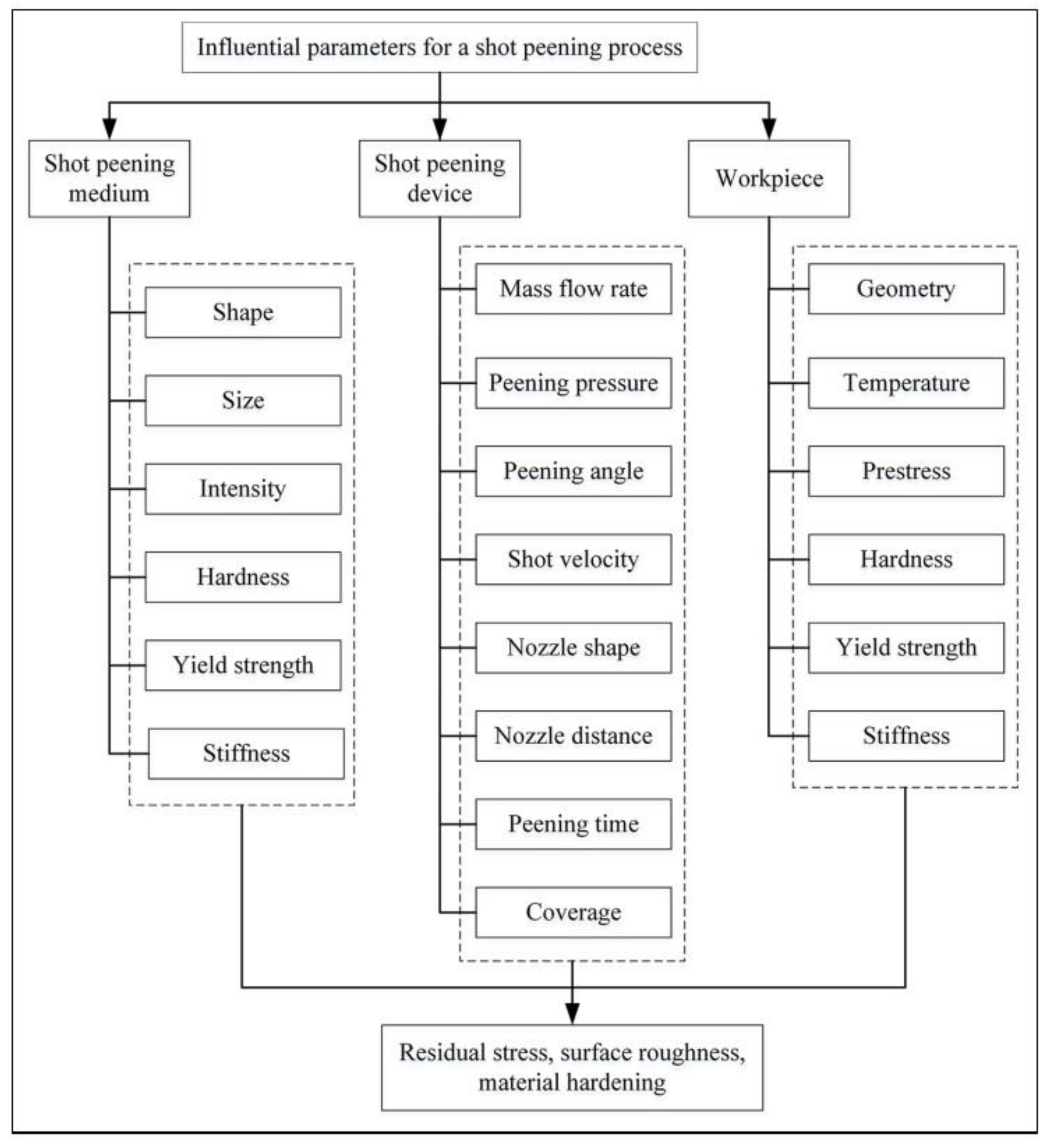
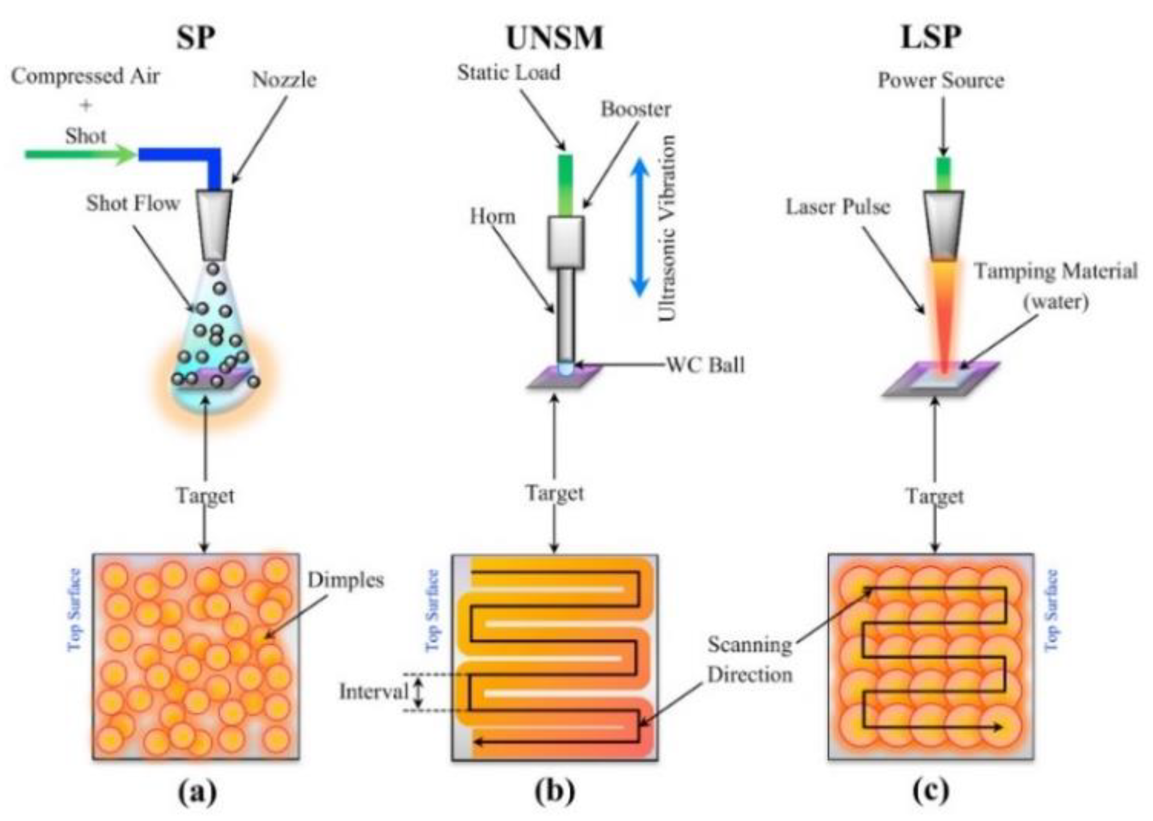
2. Shot Peening
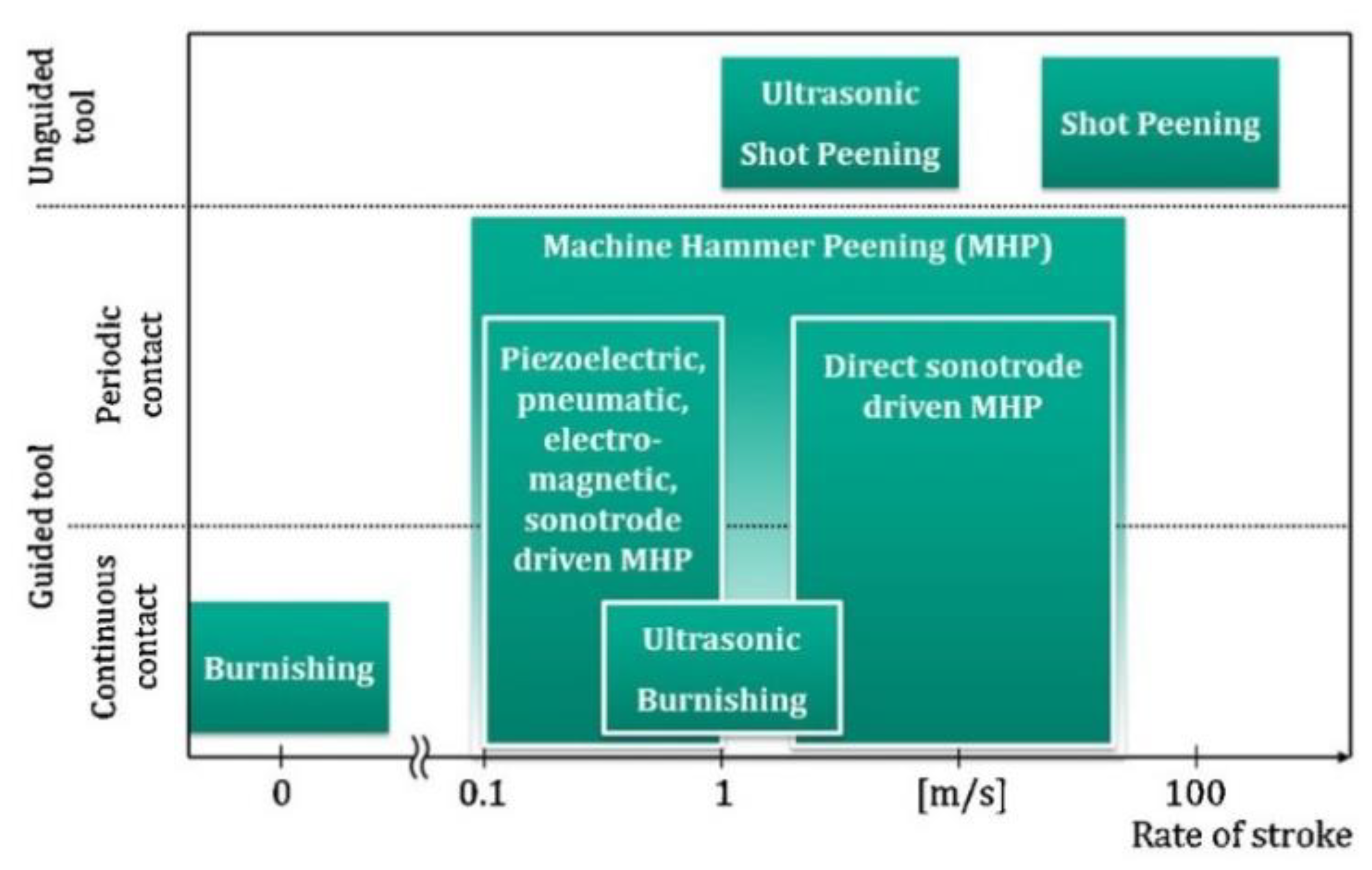
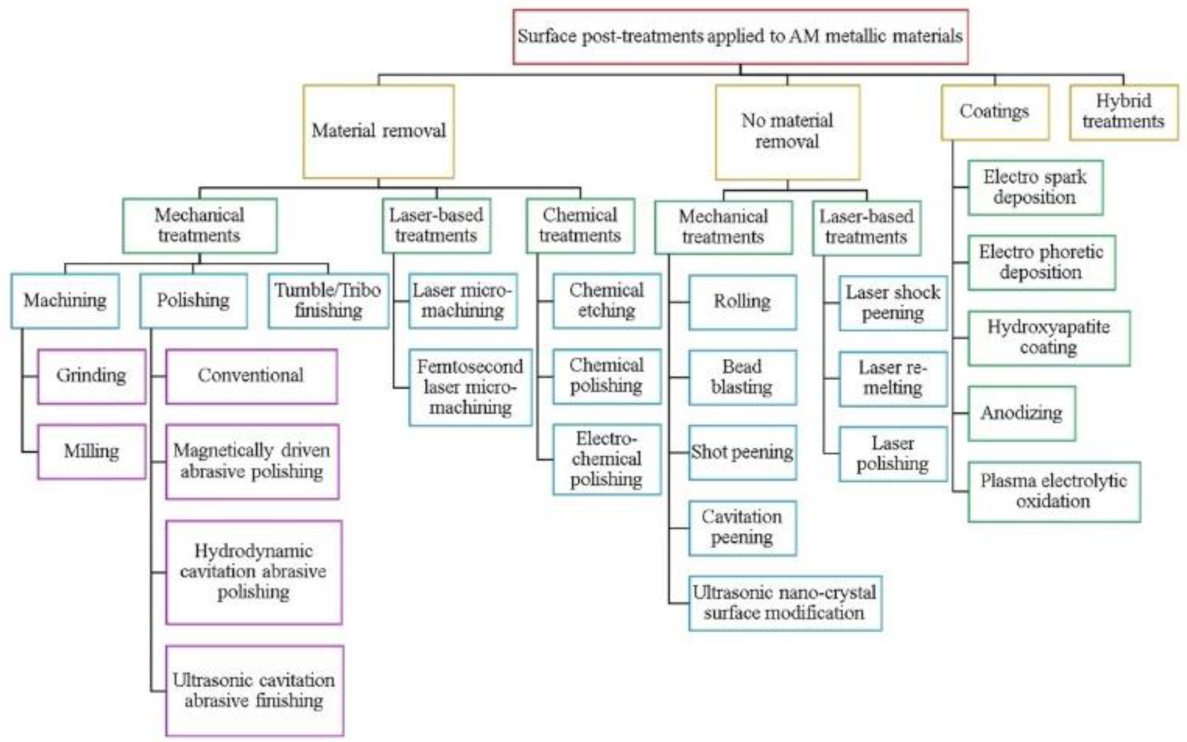
3. Peening Methods
3.1. Ultrasonic Impact Peening
3.2. Ultrasonic Nanocrystal Surface Modification
3.3. Laser Shock Peening
3.4. Flap Peening
3.5. Micro Shot Peening
3.6. Water Jet Peening
3.7. Oil Jet Peening
3.8. Ultrasonic Shot Peening
4. Cavitation Peening
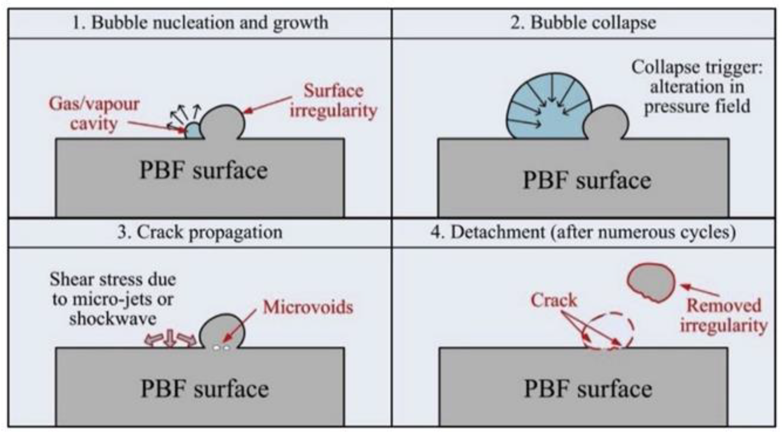
4.1. Cavitation
- optical cavitation;
- molecular cavitation;
- acoustic cavitation;
- hydrodynamic cavitation.
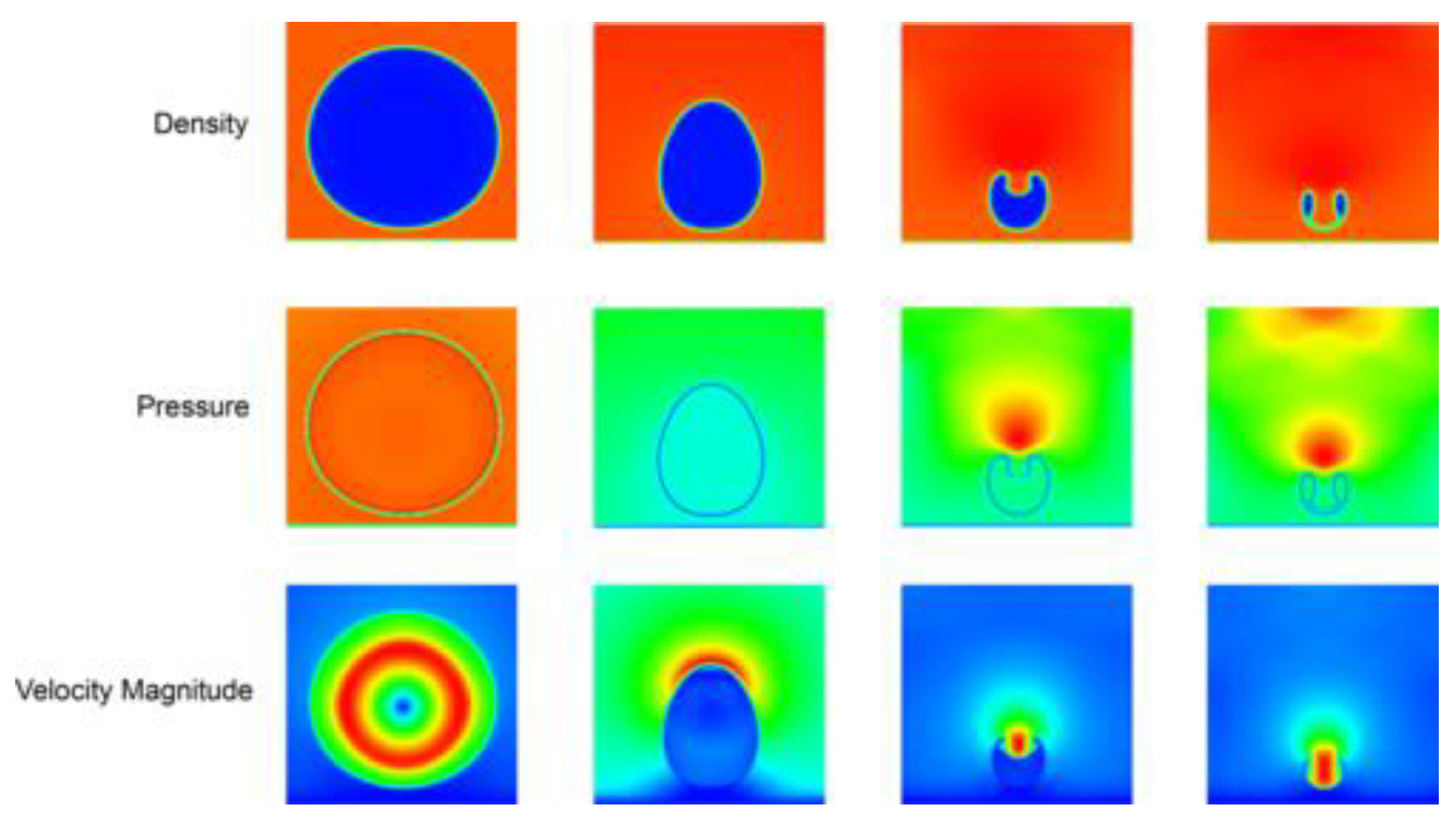
4.1.1. Hydrodynamic Cavitation
4.1.2. Acoustic Cavitation
5. Shot Peening Effects
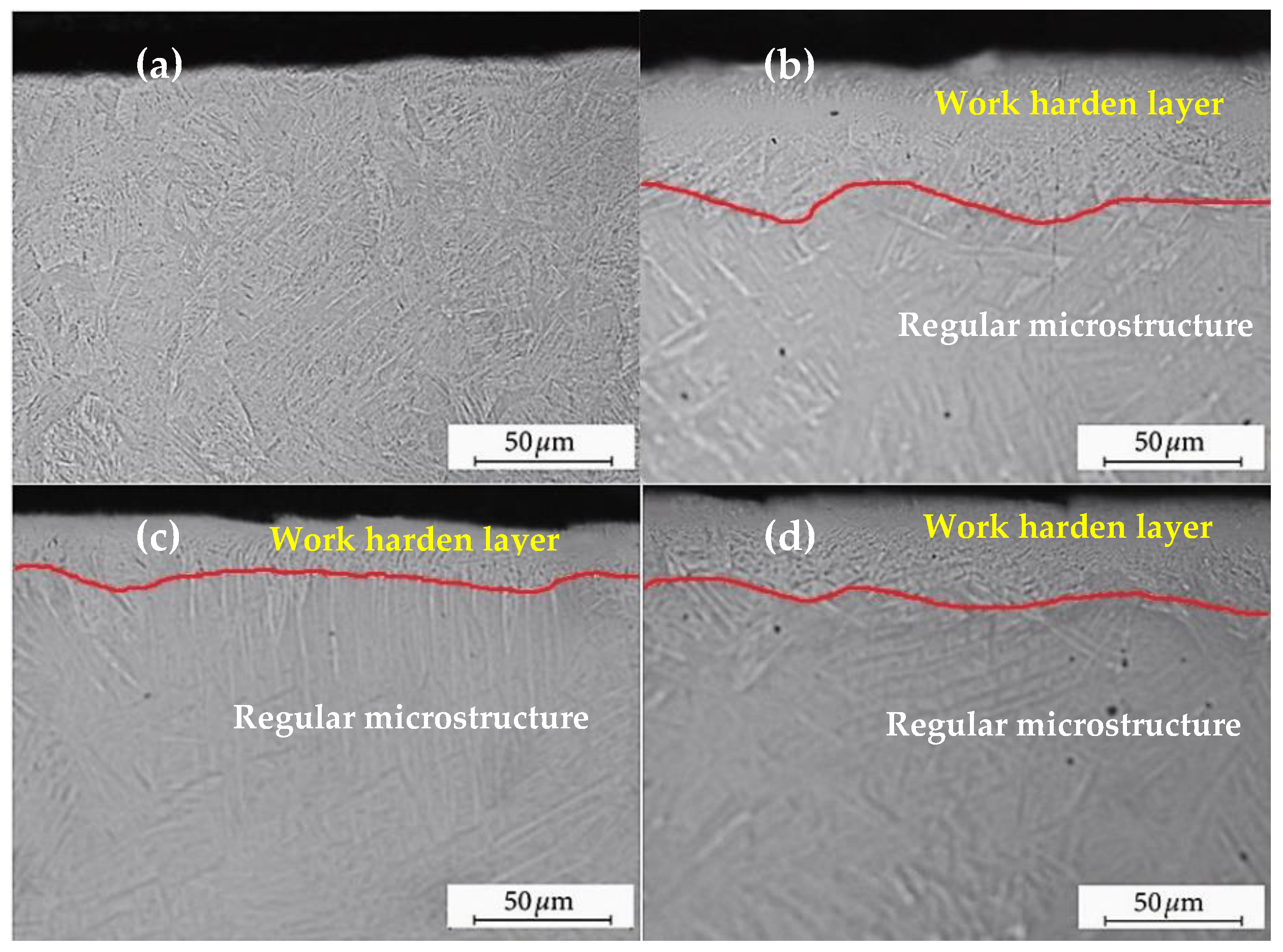
6. Cavitation Peening Effects
7. Modification of Components Produced by Additive Technologies
8. Summary
Author Contributions
Funding
Institutional Review Board Statement
Informed Consent Statement
Data Availability Statement
Conflicts of Interest
References
- Garcias, J.F.; M artins, R.F.; Branco, R.; Marciniak, Z.; Macek, W.; Pereira, C.; Santos, C. Quasistatic and Fatigue Behavior of an AISI H13 Steel Obtained by Additive Manufacturing and Conventional Method. Fatigue Fract. Eng. Mater. Struct. 2021, 44, 3384–3398. [Google Scholar] [CrossRef]
- Spalek, N.; Brunow, J.; Braun, M.; Rutner, M. WAAM-Fabricated Laminated Metal Composites. Metals 2021, 11, 1948. [Google Scholar] [CrossRef]
- Sonal, S.; Lee, J. Recent Advances in Additive Manufacturing of High Entropy Alloys and Their Nuclear and Wear-Resistant Applications. Metals 2021, 11, 1980. [Google Scholar] [CrossRef]
- Soyama, H. Fundamentals and Applications of Cavitation Peening. In Advanced Surface Enhancement; Itoh, S., Shukla, S., Eds.; Lecture Notes in Mechanical Engineering; Springer: Singapore, 2020; pp. 76–87. ISBN 9789811500534. [Google Scholar]
- Luo, P.; Wang, Z.; Wu, G.; Wang, Y.; Cheng, M. Literature Review on State of the Art in Shot Peening in the Last Decade (2006–2015). In Proceedings of the Advanced High Strength Steel and Press Hardening Xi’an, China, 25–27 August 2017; WORLD SCIENTIFIC: Xi’an, China, 2017; pp. 406–419. [Google Scholar]
- Lim, Y.; Murugesan, P.; Jung, S.; Lee, H. Evaluation of Residual Stress from Ultrasonic Cavitation Peening Using Cavitation Pit Analysis and FEA. Int. J. Mech. Sci. 2021, 198, 106352. [Google Scholar] [CrossRef]
- Holmberg, J.; Wretland, A.; Berglund, J.; Beno, T. A Detailed Investigation of Residual Stresses after Milling Inconel 718 Using Typical Production Parameters for Assessment of Affected Depth. Mater. Today Commun. 2020, 24, 100958. [Google Scholar] [CrossRef]
- Ma, Y.; Zhang, Y.; Zhang, H.; Xue, C. Residual Stress Analysis of the Multi-Stage Forging Process of a Nickel-Based Superalloy Turbine Disc. Proc. Inst. Mech. Eng. Part G J. Aerosp. Eng. 2013, 227, 213–225. [Google Scholar] [CrossRef]
- Bergström, Y.; Granbom, Y.; Sterkenburg, D. A Dislocation-Based Theory for the Deformation Hardening Behavior of DP Steels: Impact of Martensite Content and Ferrite Grain Size. J. Metall. 2010, 2010, 1–16. [Google Scholar] [CrossRef]
- Bassini, E.; Sivo, A.; Ugues, D. Assessment of the Hardening Behavior and Tensile Properties of a Cold-Rolled Bainitic–Ferritic Steel. Materials 2021, 14, 6662. [Google Scholar] [CrossRef] [PubMed]
- Khalaj, O.; Saebnoori, E.; Jirková, H.; Chocholatý, O.; Kučerová, L.; Hajšman, J.; Svoboda, J. The Effect of Heat Treatment on the Tribological Properties and Room Temperature Corrosion Behavior of Fe–Cr–Al-Based OPH Alloy. Materials 2020, 13, 5465. [Google Scholar] [CrossRef]
- Szala, M.; Winiarski, G.; Wójcik, Ł.; Bulzak, T. Effect of Annealing Time and Temperature Parameters on the Microstructure, Hardness, and Strain-Hardening Coefficients of 42CrMo4 Steel. Materials 2020, 13, 2022. [Google Scholar] [CrossRef] [PubMed]
- Kubit, A.; Bucior, M.; Zielecki, W.; Stachowicz, F. The Impact of Heat Treatment and Shot Peening on the Fatigue Strength of 51CrV4 Steel. Procedia Struct. Integr. 2016, 2, 3330–3336. [Google Scholar] [CrossRef]
- Ahn, S.-H.; Heo, J.; Kim, J.; Hwang, H.; Cho, I.-S. The Effect of Baking Heat Treatment on the Fatigue Strength and Life of Shot Peened 4340M Landing Gear Steel. Materials 2020, 13, 5711. [Google Scholar] [CrossRef]
- Mahmood, M.A.; Chioibasu, D.; Ur Rehman, A.; Mihai, S.; Popescu, A.C. Post-Processing Techniques to Enhance the Quality of Metallic Parts Produced by Additive Manufacturing. Metals 2022, 12, 77. [Google Scholar] [CrossRef]
- Macek, W.; Branco, R.; Trembacz, J.; Costa, J.D.; Ferreira, J.A.M.; Capela, C. Effect of Multiaxial Bending-Torsion Loading on Fracture Surface Parameters in High-Strength Steels Processed by Conventional and Additive Manufacturing. Eng. Fail. Anal. 2020, 118, 104784. [Google Scholar] [CrossRef]
- Macek, W.; Martins, R.F.; Branco, R.; Marciniak, Z.; Szala, M.; Wroński, S. Fatigue Fracture Morphology of AISI H13 Steel Obtained by Additive Manufacturing. Int. J. Fract. 2022. [Google Scholar] [CrossRef]
- Soyama, H.; Takeo, F. Effect of Various Peening Methods on the Fatigue Properties of Titanium Alloy Ti6Al4V Manufactured by Direct Metal Laser Sintering and Electron Beam Melting. Materials 2020, 13, 2216. [Google Scholar] [CrossRef]
- Ngo, T.D.; Kashani, A.; Imbalzano, G.; Nguyen, K.T.Q.; Hui, D. Additive Manufacturing (3D Printing): A Review of Materials, Methods, Applications and Challenges. Compos. Part B Eng. 2018, 143, 172–196. [Google Scholar] [CrossRef]
- Bagherifard, S. Enhancing the Structural Performance of Lightweight Metals by Shot Peening. Adv. Eng. Mater. 2019, 21, 1801140. [Google Scholar] [CrossRef]
- John, M.; Kalvala, P.R.; Misra, M.; Menezes, P.L. Peening Techniques for Surface Modification: Processes, Properties, and Applications. Materials 2021, 14, 3841. [Google Scholar] [CrossRef] [PubMed]
- Skoczylas, A. Vibratory Shot Peening of Elements Cut with Abrasive Water Jet. Adv. Sci. Technol. Res. J. 2022, 16, 39–49. [Google Scholar]
- Żebrowski, R.; Walczak, M.; Klepka, T.; Pasierbiewicz, K. Effect of the Shot Peening on Surface Properties of Ti-6Al-4V Alloy Produced by Means of DMLS Technology. EiN 2018, 21, 46–53. [Google Scholar] [CrossRef]
- Bagheri, S.; Guagliano, M. Review of Shot Peening Processes to Obtain Nanocrystalline Surfaces in Metal Alloys. Surf. Eng. 2009, 25, 3–14. [Google Scholar] [CrossRef]
- Macek, W.; Szala, M.; Kowalski, M.; Gargasas, J.; Rehmus-Forc, A.; Deptuła, A. Shot Peening Intensity Effect on Bending Fatigue Strength of S235, S355 and P460 Structural Steels. IOP Conf. Ser. Mater. Sci. Eng. 2019, 710, 012035. [Google Scholar] [CrossRef]
- Niku-Lari, A. OVERVIEW ON THE SHOT PEENING PROCESS. In Advances in Surface Treatments; Elsevier: Amsterdam, The Netherlands, 1987; pp. 155–170. ISBN 978-0-08-034923-7. [Google Scholar]
- Arun Prakash, N.; Gnanamoorthy, R.; Kamaraj, M. Fretting Wear Behavior of Fine Grain Structured Aluminium Alloy Formed by Oil Jet Peening Process under Dry Sliding Condition. Wear 2012, 294–295, 427–437. [Google Scholar] [CrossRef]
- Gujba, A.; Medraj, M. Laser Peening Process and Its Impact on Materials Properties in Comparison with Shot Peening and Ultrasonic Impact Peening. Materials 2014, 7, 7925–7974. [Google Scholar] [CrossRef]
- Chen, J.S.; Desai, D.A.; Heyns, S.P.; Pietra, F. Literature Review of Numerical Simulation and Optimisation of the Shot Peening Process. Adv. Mech. Eng. 2019, 11, 168781401881827. [Google Scholar] [CrossRef]
- Schulze, V.; Bleicher, F.; Groche, P.; Guo, Y.B.; Pyun, Y.S. Surface Modification by Machine Hammer Peening and Burnishing. CIRP Ann. 2016, 65, 809–832. [Google Scholar] [CrossRef]
- Statnikov, E.S.; Korolkov, O.V.; Vityazev, V.N. Physics and Mechanism of Ultrasonic Impact. Ultrasonics 2006, 44, e533–e538. [Google Scholar] [CrossRef] [PubMed]
- Statnikov, E.S.; Muktepavel, V.O.; Blomqvist, A. Comparison of Ultrasonic Impact Treatment (UIT) and Other Fatigue Life Improvement Methods. Weld World 2002, 46, 20–32. [Google Scholar] [CrossRef]
- Mordyuk, B.N.; Prokopenko, G.I. Ultrasonic Impact Peening for the Surface Properties’ Management. J. Sound Vib. 2007, 308, 855–866. [Google Scholar] [CrossRef]
- Chan, W.L.; Cheng, H.K.F. Hammer Peening Technology—the Past, Present, and Future. Int. J. Adv. Manuf. Technol. 2022, 118, 683–701. [Google Scholar] [CrossRef]
- Amanov, A.; Penkov, O.V.; Pyun, Y.-S.; Kim, D.-E. Effects of Ultrasonic Nanocrystalline Surface Modification on the Tribological Properties of AZ91D Magnesium Alloy. Tribol. Int. 2012, 54, 106–113. [Google Scholar] [CrossRef]
- Cherif, A.; Pyoun, Y.; Scholtes, B. Effects of Ultrasonic Nanocrystal Surface Modification (UNSM) on Residual Stress State and Fatigue Strength of AISI 304. J. Materi. Eng. Perform. 2010, 19, 282–286. [Google Scholar] [CrossRef]
- Zhao, W.; Liu, D.; Chiang, R.; Qin, H.; Zhang, X.; Zhang, H.; Liu, J.; Ren, Z.; Zhang, R.; Doll, G.L.; et al. Effects of Ultrasonic Nanocrystal Surface Modification on the Surface Integrity, Microstructure, and Wear Resistance of 300M Martensitic Ultra-High Strength Steel. J. Mater. Processing Technol. 2020, 285, 116767. [Google Scholar] [CrossRef]
- Kim, M.S.; Park, S.H.; Pyun, Y.S.; Shim, D.S. Optimization of Ultrasonic Nanocrystal Surface Modification for Surface Quality Improvement of Directed Energy Deposited Stainless Steel 316L. J. Mater. Res. Technol. 2020, 9, 15102–15122. [Google Scholar] [CrossRef]
- Liu, R.; Yuan, S.; Lin, N.; Zeng, Q.; Wang, Z.; Wu, Y. Application of Ultrasonic Nanocrystal Surface Modification (UNSM) Technique for Surface Strengthening of Titanium and Titanium Alloys: A Mini Review. J. Mater. Res. Technol. 2021, 11, 351–377. [Google Scholar] [CrossRef]
- Ma, C.; Dong, Y.; Ye, C. Improving Surface Finish of 3D-Printed Metals by Ultrasonic Nanocrystal Surface Modification. Procedia CIRP 2016, 45, 319–322. [Google Scholar] [CrossRef]
- Ye, C.; Telang, A.; Gill, A.S.; Suslov, S.; Idell, Y.; Zweiacker, K.; Wiezorek, J.M.K.; Zhou, Z.; Qian, D.; Mannava, S.R.; et al. Gradient Nanostructure and Residual Stresses Induced by Ultrasonic Nano-Crystal Surface Modification in 304 Austenitic Stainless Steel for High Strength and High Ductility. Mater. Sci. Eng. A 2014, 613, 274–288. [Google Scholar] [CrossRef]
- Suh, M.-S.; Suh, C.-M.; Pyun, Y.-S. Very High Cycle Fatigue Characteristics of a Chrome-Molybdenum Steel Treated by Ultrasonic Nanocrystal Surface Modification Technique: NANOSKINNED SCM435 UNDER VHCF. Fatigue Fract. Eng. Mater. Struct. 2013, 36, 769–778. [Google Scholar] [CrossRef]
- Clauer, A.H. Laser Shock Peening for Fatigue Resistance. Surf. Perform. Titan. 1996, 217, 230. [Google Scholar]
- Ding, K.; Ye, L.; Ye, L. Laser Shock Peening: Performance and Process Simulation; Woodhead Publishing in Materials; CRC Press [u.a.]: Boca Raton, FL, USA, 2006; ISBN 978-1-84569-109-7. [Google Scholar]
- Zhang, X.C.; Zhang, Y.K.; Lu, J.Z.; Xuan, F.Z.; Wang, Z.D.; Tu, S.T. Improvement of Fatigue Life of Ti–6Al–4V Alloy by Laser Shock Peening. Mater. Sci. Eng. A 2010, 527, 3411–3415. [Google Scholar] [CrossRef]
- Maleki, E.; Unal, O.; Guagliano, M.; Bagherifard, S. The Effects of Shot Peening, Laser Shock Peening and Ultrasonic Nanocrystal Surface Modification on the Fatigue Strength of Inconel 718. Mater. Sci. Eng. A 2021, 810, 141029. [Google Scholar] [CrossRef]
- Abushgair, K. Experimental Studies the Effect of Flap Peening Process on Aluminum Alloys. Jordan J. Mech. Ind. Eng. 2017, 11, 173–180. [Google Scholar]
- Harada, Y.; Fukaura, K.; Haga, S. Influence of Microshot Peening on Surface Layer Characteristics of Structural Steel. J. Mater. Processing Technol. 2007, 191, 297–301. [Google Scholar] [CrossRef]
- Zhang, J.; Li, W.; Wang, H.; Song, Q.; Lu, L.; Wang, W.; Liu, Z. A Comparison of the Effects of Traditional Shot Peening and Micro-Shot Peening on the Scuffing Resistance of Carburized and Quenched Gear Steel. Wear 2016, 368–369, 253–257. [Google Scholar] [CrossRef]
- Li, X.; Zhang, J.; Yang, B.; Zhang, J.; Wu, M.; Lu, L. Effect of Micro-Shot Peening, Conventional Shot Peening and Their Combination on Fatigue Property of EA4T Axle Steel. J. Mater. Processing Technol. 2020, 275, 116320. [Google Scholar] [CrossRef]
- Zhang, J.; Li, H.; Yang, B.; Wu, B.; Zhu, S. Fatigue Properties and Fatigue Strength Evaluation of Railway Axle Steel: Effect of Micro-Shot Peening and Artificial Defect. Int. J. Fatigue 2020, 132, 105379. [Google Scholar] [CrossRef]
- Ahmed, A.A.; Mhaede, M.; Wollmann, M.; Wagner, L. Effect of Micro Shot Peening on the Mechanical Properties and Corrosion Behavior of Two Microstructure Ti–6Al–4V Alloy. Appl. Surf. Sci. 2016, 363, 50–58. [Google Scholar] [CrossRef]
- Soyama, H. Cavitation Peening: A Review. Metals 2020, 10, 270. [Google Scholar] [CrossRef]
- Soyama, H.; Sanders, D. Use of an Abrasive Water Cavitating Jet and Peening Process to Improve the Fatigue Strength of Titanium Alloy 6Al-4V Manufactured by the Electron Beam Powder Bed Melting (EBPB) Additive Manufacturing Method. JOM 2019, 71, 4311–4318. [Google Scholar] [CrossRef]
- Sadasivam, B.; Hizal, A.; Arola, D. Abrasive Waterjet Peening with Elastic Prestress: A Parametric Evaluation. Int. J. Mach. Tools Manuf. 2009, 49, 134–141. [Google Scholar] [CrossRef]
- Arun Prakash, N.; Gnanamoorthy, R.; Kamaraj, M. Microstructural Evolution and Mechanical Properties of Oil Jet Peened Aluminium Alloy, AA6063-T6. Mater. Des. 2010, 31, 4066–4075. [Google Scholar] [CrossRef]
- Grinspan, A.S.; Gnanamoorthy, R. Surface Modification by Oil Jet Peening in Al Alloys, AA6063-T6 and AA6061-T4. Appl. Surf. Sci. 2006, 253, 997–1005. [Google Scholar] [CrossRef]
- Rakita, M.; Wang, M.; Han, Q.; Liu, Y.; Yin, F. Ultrasonic Shot Peening. Int. J. Comput. Mater. Sci. Surf. Eng. 2013, 5, 189. [Google Scholar] [CrossRef]
- Dai, K.; Shaw, L. Comparison between Shot Peening and Surface Nanocrystallization and Hardening Processes. Mater. Sci. Eng. A 2007, 463, 46–53. [Google Scholar] [CrossRef]
- Yin, F.; Rakita, M.; Hu, S.; Han, Q. Overview of Ultrasonic Shot Peening. Surf. Eng. 2017, 33, 651–666. [Google Scholar] [CrossRef]
- Shiryaev, A.A.; Trofimov, V.N.; Karmanov, V.V.; Vindokurov, D.V. Effect of Parameters of Ultrasonic Shot Peening on the Physicomechanical Properties of the Surface Layer of Flat Samples. IOP Conf. Ser. Mater. Sci. Eng. 2020, 731, 012025. [Google Scholar] [CrossRef]
- Muruganandhan, R.; Mugilvalavan, M.; Thirumavalavan, K.; Yuvaraj, N. Investigation of Water Jet Peening Process Parameters on AL6061-T6. Surf. Eng. 2018, 34, 330–340. [Google Scholar] [CrossRef]
- Ju, D.Y.; Han, B. Investigation of Water Cavitation Peening-Induced Microstructures in the near-Surface Layer of Pure Titanium. J. Mater. Processing Technol. 2009, 209, 4789–4794. [Google Scholar] [CrossRef]
- Soyama, H.; Macodiyo, D.O.; Mall, S. Compressive Residual Stress into Titanium Alloy Using Cavitation Shotless Peening Method. Tribol. Lett. 2004, 17, 501–504. [Google Scholar] [CrossRef]
- Ijiri, M.; Ogi, T.; Yoshimura, T. High-Temperature Corrosion Behavior of High-Temperature and High-Pressure Cavitation Processed Cr–Mo Steel Surface. Heliyon 2020, 6, e04698. [Google Scholar] [CrossRef]
- Odhiambo, D.; Soyama, H. Cavitation Shotless Peening for Improvement of Fatigue Strength of Carbonized Steel. Int. J. Fatigue 2003, 25, 1217–1222. [Google Scholar] [CrossRef]
- Ijiri, M.; Shimonishi, D.; Nakagawa, D.; Yoshimura, T. Evolution of Microstructure from the Surface to the Interior of Cr-Mo Steel by Water Jet Peening. MSA 2017, 08, 708–715. [Google Scholar] [CrossRef]
- Arrojo, S.; Benito, Y. A Theoretical Study of Hydrodynamic Cavitation. Ultrason. Sonochemistry 2008, 15, 203–211. [Google Scholar] [CrossRef] [PubMed]
- Braeutigam, P.; Franke, M.; Wu, Z.-L.; Ondruschka, B. Role of Different Parameters in the Optimization of Hydrodynamic Cavitation. Chem. Eng. Technol. 2010, 33, 932–940. [Google Scholar] [CrossRef]
- Franc, J.-P.; Michel, J.-M. Fundamentals of Cavitation; Springer Science & Business Media: Dordrecht, NY, USA, 2006; Volume 76. [Google Scholar]
- Barnocky, G.; Davis, R.H. Elastohydrodynamic Collision and Rebound of Spheres: Experimental Verification. Phys. Fluids 1988, 31, 1324. [Google Scholar] [CrossRef]
- Sirignano, W.A.; Mehring, C. Review of Theory of Distortion and Disintegration of Liquid Streams. Prog. Energy Combust. Sci. 2000, 26, 609–655. [Google Scholar] [CrossRef]
- Sun, X.; Liu, J.; Ji, L.; Wang, G.; Zhao, S.; Yoon, J.Y.; Chen, S. A Review on Hydrodynamic Cavitation Disinfection: The Current State of Knowledge. Sci. Total Environ. 2020, 737, 139606. [Google Scholar] [CrossRef]
- Jones, O.C.; Zuber, N. Bubble Growth in Variable Pressure Fields. J. Heat Transf. 1978, 100, 453–459. [Google Scholar] [CrossRef]
- Neppiras, E.A. Acoustic Cavitation. Phys. Rep. 1980, 61, 159–251. [Google Scholar] [CrossRef]
- Plesset, M.S.; Chapman, R.B. Collapse of an Initially Spherical Vapour Cavity in the Neighbourhood of a Solid Boundary. J. Fluid Mech. 1971, 47, 283–290. [Google Scholar] [CrossRef]
- Naude, C.F.; Ellis, A.T. On the Mechanism of Cavitation Damage by Nonhemispherical Cavities Collapsing in Contact with a Solid Boundary. J. Basic Eng. 1961, 83, 648–656. [Google Scholar] [CrossRef]
- Lauterborn, W.; Bolle, H. Experimental Investigations of Cavitation-Bubble Collapse in the Neighbourhood of a Solid Boundary. J. Fluid Mech. 1975, 72, 391. [Google Scholar] [CrossRef]
- Vogel, A.; Lauterborn, W.; Timm, R. Optical and Acoustic Investigations of the Dynamics of Laser-Produced Cavitation Bubbles near a Solid Boundary. J. Fluid Mech. 1989, 206, 299–338. [Google Scholar] [CrossRef]
- Benjamin, T.B.; Ellis, A.T. The Collapse of Cavitation Bubbles and the Pressures Thereby Produced against Solid Boundaries. Philos. Trans. R. Soc. London. Ser. A Math. Phys. Sci. 1966, 260, 221–240. [Google Scholar]
- Blake, J.R.; Gibson, D.C. Cavitation Bubbles Near Boundaries. Annu. Rev. Fluid Mech. 1987, 19, 99–123. [Google Scholar] [CrossRef]
- Ezzatneshan, E.; Vaseghnia, H. Simulation of Collapsing Cavitation Bubbles in Various Liquids by Lattice Boltzmann Model Coupled with the Redlich-Kwong-Soave Equation of State. Phys. Rev. E 2020, 102, 053309. [Google Scholar] [CrossRef]
- Chahine, G.L. Interaction Between an Oscillating Bubble and a Free Surface. J. Fluids Eng. 1977, 99, 709–716. [Google Scholar] [CrossRef]
- Chahine, G.L.; Duraiswami, R. Dynamical Interactions in a Multi-Bubble Cloud. J. Fluids Eng. 1992, 114, 680–686. [Google Scholar] [CrossRef]
- Dear, J.P.; Field, J.E. A Study of the Collapse of Arrays of Cavities. J. Fluid Mech. 1988, 190, 409–425. [Google Scholar] [CrossRef]
- Li, S.C. Introduction. In Series on Hydraulic Machinery; Distributed By World Scientific Publishing Co.; Imperial College Press: London, UK, 2000; Volume 1, pp. 1–8. ISBN 978-1-86094-257-0. [Google Scholar]
- Wang, B.; Su, H.; Zhang, B. Hydrodynamic Cavitation as a Promising Route for Wastewater Treatment—A Review. Chem. Eng. J. 2021, 412, 128685. [Google Scholar] [CrossRef]
- Sun, X.; Chen, S.; Liu, J.; Zhao, S.; Yoon, J.Y. Hydrodynamic Cavitation: A Promising Technology for Industrial-Scale Synthesis of Nanomaterials. Front. Chem. 2020, 8, 259. [Google Scholar] [CrossRef] [PubMed]
- Weil, E.D.; Levchik, S.V. Phosphorus Flame Retardants. In Kirk-Othmer Encyclopedia of Chemical Technology, 1st ed.; John Wiley & Sons, Inc.: Hoboken, NJ, USA, 2017; ISBN 978-0-471-48494-3. [Google Scholar]
- Ashokkumar, M. The Characterization of Acoustic Cavitation Bubbles—An Overview. Ultrason. Sonochem. 2011, 18, 864–872. [Google Scholar] [CrossRef]
- Szala, M.; Walczak, M.; Hejwowski, T. Factors Influencing Cavitation Erosion of NiCrSiB Hardfacings Deposited by Oxy-Acetylene Powder Welding on Grey Cast Iron. Adv. Sci. Technol. Res. J. 2021, 15, 376–386. [Google Scholar] [CrossRef]
- Szala, M.; Świetlicki, A.; Sofińska-Chmiel, W. Cavitation erosion of electrostatic spray polyester coatings with different surface finish. Bull. Pol. Acad. Sci. Tech. Sci. 2021, 69, e137519. [Google Scholar] [CrossRef]
- Szala, M.; Łatka, L.; Awtoniuk, M.; Winnicki, M.; Michalak, M. Neural Modelling of APS Thermal Spray Process Parameters for Optimizing the Hardness, Porosity and Cavitation Erosion Resistance of Al2O3-13 Wt% TiO2 Coatings. Processes 2020, 8, 1544. [Google Scholar] [CrossRef]
- Szala, M. Application of Computer Image Analysis Software for Determining Incubation Period of Cavitation Erosion—Preliminary Results. ITM Web Conf. 2017, 15, 06003. [Google Scholar] [CrossRef]
- Szala, M.; Łatka, L.; Walczak, M.; Winnicki, M. Comparative Study on the Cavitation Erosion and Sliding Wear of Cold-Sprayed Al/Al2O3 and Cu/Al2O3 Coatings, and Stainless Steel, Aluminium Alloy, Copper and Brass. Metals 2020, 10, 856. [Google Scholar] [CrossRef]
- Szala, M.; Chocyk, D.; Skic, A.; Kamiński, M.; Macek, W.; Turek, M. Effect of Nitrogen Ion Implantation on the Cavitation Erosion Resistance and Cobalt-Based Solid Solution Phase Transformations of HIPed Stellite 6. Materials 2021, 14, 2324. [Google Scholar] [CrossRef] [PubMed]
- Szala, M.; Walczak, M.; Świetlicki, A. Effect of Microstructure and Hardness on Cavitation Erosion and Dry Sliding Wear of HVOF Deposited CoNiCrAlY, NiCoCrAlY and NiCrMoNbTa Coatings. Materials 2021, 15, 93. [Google Scholar] [CrossRef] [PubMed]
- Gao, G.; Zhang, Z. Cavitation Erosion Mechanism of 2Cr13 Stainless Steel. Wear 2022, 488–489, 204137. [Google Scholar] [CrossRef]
- Mitelea, I.; Bordeaşu, I.; Riemschneider, E.; Uţu, I.D.; Crăciunescu, C.M. Cavitation Erosion Improvement Following TIG Surface-Remelting of Gray Cast Iron. Wear 2022, 496–497, 204282. [Google Scholar] [CrossRef]
- Krella, A.K.; Zakrzewska, D.E.; Marchewicz, A. The Resistance of S235JR Steel to Cavitation Erosion. Wear 2020, 452–453, 203295. [Google Scholar] [CrossRef]
- Steller, J. Erosive Wear Modelling by Means of the Fractional Approach. Wear 2021, 484–485, 204015. [Google Scholar] [CrossRef]
- Szala, M.; Dudek, A.; Maruszczyk, A.; Walczak, M.; Chmiel, J.; Kowal, M. Effect of Atmospheric Plasma Sprayed TiO2-10% NiAl Cermet Coating Thickness on Cavitation Erosion, Sliding and Abrasive Wear Resistance. Acta Phys. Pol. A 2019, 136, 335–341. [Google Scholar] [CrossRef]
- Bag, A.; Lévesque, M.; Brochu, M. Effect of Shot Peening on Short Crack Propagation in 300M Steel. Int. J. Fatigue 2020, 131, 105346. [Google Scholar] [CrossRef]
- Effect of Shot Peening on the Residual Stress and Microstructure of Duplex Stainless Steel | Elsevier Enhanced Reader. Available online: https://reader.elsevier.com/reader/sd/pii/S0257897213003204?token=4AF40F6885BE710EFC20C62844681979E26E2C57B10B05F64E0A79C135CFDD03F5BCECE7CB0D8FA0CF27D13257F52759&originRegion=eu-west-1&originCreation=20211208123852 (accessed on 8 December 2021).
- Al-Obaid, Y.F. The Effect of Shot Peening on Stress Corrosion Cracking Behaviour of 2205-Duplex Stainless Steel. Eng. Fract. Mech. 1995, 51, 19–25. [Google Scholar] [CrossRef]
- Maleki, E.; Unal, O.; Bandini, M.; Guagliano, M.; Bagherifard, S. Individual and Synergistic Effects of Thermal and Mechanical Surface Post-Treatments on Wear and Corrosion Behavior of Laser Powder Bed Fusion AlSi10Mg. J. Mater. Processing Technol. 2022, 302, 117479. [Google Scholar] [CrossRef]
- Han, X.; Zhang, Z.; Wang, B.; Thrush, S.J.; Barber, G.C.; Qiu, F. Microstructures, Compressive Residual Stress, Friction Behavior, and Wear Mechanism of Quenched and Tempered Shot Peened Medium Carbon Steel. Wear 2022, 488–489, 204131. [Google Scholar] [CrossRef]
- Gopi, R.; Saravanan, I.; Devaraju, A.; Loganathan, G. babu Investigation of Shot Peening Process on Stainless Steel and Its Effects for Tribological Applications. Mater. Today Proc. 2020, 22, 580–584. [Google Scholar] [CrossRef]
- Çakir, F.H.; Öteyaka, M.Ö.; Er, Ü.; Bozkurt, F. Enhancing Wear Resistance of AISI 304 Alloy with Shot Peening and Investigation of Corrosion Behaviour in Marine Water. Trans. IMF 2021, 99, 194–202. [Google Scholar] [CrossRef]
- Matsui, M.; Kakishima, H. Improvement of Tribological Performance of Steel by Solid Lubricant Shot-Peening in Dry Rolling/Sliding Contact Wear Tests. Wear 2006, 260, 669–673. [Google Scholar] [CrossRef]
- Kovacı, H.; Hacısalihoğlu, İ.; Yetim, A.F.; Çelik, A. Effects of Shot Peening Pre-Treatment and Plasma Nitriding Parameters on the Structural, Mechanical and Tribological Properties of AISI 4140 Low-Alloy Steel. Surf. Coat. Technol. 2019, 358, 256–265. [Google Scholar] [CrossRef]
- Skoczylas, A.; Zaleski, K.; Zaleski, R.; Gorgol, M. Analysis of Surface Properties of Nickel Alloy Elements Exposed to Impulse Shot Peening with the Use of Positron Annihilation. Materials 2021, 14, 7328. [Google Scholar] [CrossRef] [PubMed]
- Silva, K.H.S.; Carneiro, J.R.; Coelho, R.S.; Pinto, H.; Brito, P. Influence of Shot Peening on Residual Stresses and Tribological Behavior of Cast and Austempered Ductile Iron. Wear 2019, 440–441, 203099. [Google Scholar] [CrossRef]
- Żebrowski, R.; Walczak, M. The Effect of Shot Peening on the Corrosion Behaviour of Ti-6Al-4V Alloy Made by DMLS. Adv. Mater. Sci. 2018, 18, 43–54. [Google Scholar] [CrossRef]
- Benedetti, M.; Torresani, E.; Leoni, M.; Fontanari, V.; Bandini, M.; Pederzolli, C.; Potrich, C. The Effect of Post-Sintering Treatments on the Fatigue and Biological Behavior of Ti-6Al-4V ELI Parts Made by Selective Laser Melting. J. Mech. Behav. Biomed. Mater. 2017, 71, 295–306. [Google Scholar] [CrossRef] [PubMed]
- Yıldıran Avcu, Y.; Yetik, O.; Guney, M.; Iakovakis, E.; Sınmazçelik, T.; Avcu, E. Surface, Subsurface and Tribological Properties of Ti6Al4V Alloy Shot Peened under Different Parameters. Materials 2020, 13, 4363. [Google Scholar] [CrossRef] [PubMed]
- Walczak, M.; Szala, M. Effect of Shot Peening on the Surface Properties, Corrosion and Wear Performance of 17-4PH Steel Produced by DMLS Additive Manufacturing. Archiv. Civ. Mech. Eng. 2021, 21, 157. [Google Scholar] [CrossRef]
- Naito, A.; Takakuwa, O.; Soyama, H. Development of Peening Technique Using Recirculating Shot Accelerated by Water Jet. Mater. Sci. Technol. 2012, 28, 234–239. [Google Scholar] [CrossRef]
- Dong, Z.; Wang, F.; Qian, D.; Yin, F.; Wang, H.; Wang, X.; Hu, S.; Chi, J. Enhanced Wear Resistance of the Ultrastrong Ultrasonic Shot-Peened M50 Bearing Steel with Gradient Nanograins. Metals 2022, 12, 424. [Google Scholar] [CrossRef]
- AlMangour, B.; Yang, J.-M. Improving the Surface Quality and Mechanical Properties by Shot-Peening of 17-4 Stainless Steel Fabricated by Additive Manufacturing. Materials & Design 2016, 110, 914–924. [Google Scholar] [CrossRef]
- Žagar, S.; Soyama, H.; Grum, J.; Šturm, R. Surface Integrity of Heat Treatable Magnesium Alloy AZ80A after Cavitation Peening. J. Mater. Res. Technol. 2022, 17, 2098–2107. [Google Scholar] [CrossRef]
- Thomas, M.; Lindley, T.; Rugg, D.; Jackson, M. The Effect of Shot Peening on the Microstructure and Properties of a Near-Alpha Titanium Alloy Following High Temperature Exposure. Acta Mater. 2012, 60, 5040–5048. [Google Scholar] [CrossRef]
- Wei, X. Effects of Surface Characteristics of AISI 304 Stainless Steel by Wet Shot Peening and Its Wear and Corrosion Behavior. Int. J. Electrochem. Sci. 2020, 4840–4852. [Google Scholar] [CrossRef]
- Takahashi, N.; Kugimiya, T.; Seki, T.; Terao, K.; Kunoh, T.; Mizuno, M. Application of Ultrasonic Cavitation to Metal Working and Surface Treatment of Mild Steel. JSME Int. J. 1987, 30, 1229–1236. [Google Scholar] [CrossRef]
- Gao, Y.; Wu, B.; Liu, Z.; Zhou, Y.; Shen, N.; Ding, H. Ultrasonic Cavitation Peening of Stainless Steel and Nickel Alloy. J. Manuf. Sci. Eng. 2014, 136, 014502. [Google Scholar] [CrossRef]
- Soyama, H.; Saito, K.; Saka, M. Improvement of Fatigue Strength of Aluminum Alloy by Cavitation Shotless Peening. J. Eng. Mater. Technol. 2002, 124, 135–139. [Google Scholar] [CrossRef]
- Ye, L.; Zhu, X.; He, Y.; Song, T.; Hu, W. Surface Strengthening and Grain Refinement of AZ31B Magnesium Alloy by Ultrasonic Cavitation Modification. Chin. J. Aeronaut. 2021, 34, 508–517. [Google Scholar] [CrossRef]
- Fukuda, S.; Matsui, K.; Ishigami, H.; Ando, K. Cavitation Peening to Improve the Fatigue Strength of Nitrocarburized Steel. Fatigue Fract. Eng. Mater. Struct. 2008, 31, 857–862. [Google Scholar] [CrossRef]
- Seki, M.; Someya, H.; Fujii, M.; Yoshida, A. Rolling Contact Fatigue Life of Cavitation-Peened Steel Gear. Tribol. Online 2008, 3, 116–121. [Google Scholar] [CrossRef][Green Version]
- Seki, M.; Nishie, N.; Kozai, S.; Kakuda, M.; Soyama, H.; Naito, A.; Fujii, M. Fatigue Strength of Steel Rollers and Gears Treated by Cavitation Peening with Short Processing Time (A Case of Processing Time of 1 min and 5 min): (A Case of Processing Time of 1 min and 5 min). J. Adv. Mech. Des. Syst. Manuf. 2012, 6, 33–43. [Google Scholar] [CrossRef]
- Seki, M.; Soyama, H.; Kobayashi, Y.; Gowa, D.; Fujii, M. Rolling Contact Fatigue Life of Steel Rollers Treated by Cavitation Peening and Shot Peening. J. Solid Mech. Mater. Eng. 2012, 6, 478–486. [Google Scholar] [CrossRef]
- Fatyukhin, D.S.; Nigmetzyanov, R.I.; Prikhodko, V.M.; Sukhov, A.V.; Sundukov, S.K. A Comparison of the Effects of Ultrasonic Cavitation on the Surfaces of 45 and 40Kh Steels. Metals 2022, 12, 138. [Google Scholar] [CrossRef]
- He, P.; Li, F.; Guo, J.; Chen, S.; Guo, Y.; Wang, Y.; Tan, Z. Research on the Water Cavitation Peening Process and Mechanism of TC4 Titanium Alloy. Int. J. Adv. Manuf. Technol. 2021, 112, 1259–1269. [Google Scholar] [CrossRef]
- Bai, F.; Wang, L.; Saalbach, K.-A.; Twiefel, J. A Novel Ultrasonic Cavitation Peening Approach Assisted by Water Jet. Appl. Sci. 2018, 8, 2218. [Google Scholar] [CrossRef]
- Gu, J.; Luo, C.; Zhang, P.; Ma, P.; Ren, X. Laser Cavitation Peening of Gray Cast Iron: Effect of Coverage Layer on the Surface Integrity. Appl. Surf. Sci. 2020, 521, 146295. [Google Scholar] [CrossRef]
- Brujan, E.-A.; Nahen, K.; Schmidt, P.; Vogel, A. Dynamics of Laser-Induced Cavitation Bubbles near an Elastic Boundary. J. Fluid Mech. 2001, 433, 251–281. [Google Scholar] [CrossRef]
- Kumagai, M.; Curd, M.E.; Soyama, H.; Ungár, T.; Ribárik, G.; Withers, P.J. Depth-Profiling of Residual Stress and Microstructure for Austenitic Stainless Steel Surface Treated by Cavitation, Shot and Laser Peening. Mater. Sci. Eng. A 2021, 813, 141037. [Google Scholar] [CrossRef]
- Soyama, H. Comparison between the Improvements Made to the Fatigue Strength of Stainless Steel by Cavitation Peening, Water Jet Peening, Shot Peening and Laser Peening. J. Mater. Processing Technol. 2019, 269, 65–78. [Google Scholar] [CrossRef]
- Soyama, H.; Takeo, F. Comparison between Cavitation Peening and Shot Peening for Extending the Fatigue Life of a Duralumin Plate with a Hole. J. Mater. Processing Technol. 2016, 227, 80–87. [Google Scholar] [CrossRef]
- Tan, K.L.; Yeo, S.H. Surface Finishing on IN625 Additively Manufactured Surfaces by Combined Ultrasonic Cavitation and Abrasion. Addit. Manuf. 2020, 31, 100938. [Google Scholar] [CrossRef]
- Janka, S.; Miloš, M.; Jan, H. The Improvement of the Surface Hardness of Stainless Steel and Aluminium Alloy by Ultrasonic Cavitation Peening. EPJ Web. Conf. 2017, 143, 02119. [Google Scholar] [CrossRef]
- Kim, S.-J.; Hyun, K.-Y.; Jang, S.-K. Effects of Water Cavitation Peening on Electrochemical Characteristic by Using Micro-Droplet Cell of Al–Mg Alloy. Curr. Appl. Phys. 2012, 12, S24–S30. [Google Scholar] [CrossRef]
- Salvati, E.; Lunt, A.J.G.; Heason, C.P.; Baxter, G.J.; Korsunsky, A.M. An Analysis of Fatigue Failure Mechanisms in an Additively Manufactured and Shot Peened IN 718 Nickel Superalloy. Mater. Des. 2020, 191, 108605. [Google Scholar] [CrossRef]
- Maleki, E.; Bagherifard, S.; Bandini, M.; Guagliano, M. Surface Post-Treatments for Metal Additive Manufacturing: Progress, Challenges, and Opportunities. Addit. Manuf. 2021, 37, 101619. [Google Scholar] [CrossRef]
- Soyama, H.; Okura, Y. The Use of Various Peening Methods to Improve the Fatigue Strength of Titanium Alloy Ti6Al4V Manufactured by Electron Beam Melting. AIMS Mater. Sci. 2018, 5, 1000–1015. [Google Scholar] [CrossRef]
- Żebrowski, R.; Walczak, M.; Korga, A.; Iwan, M.; Szala, M. Effect of Shot Peening on the Mechanical Properties and Cytotoxicity Behaviour of Titanium Implants Produced by 3D Printing Technology. J. Healthc. Eng. 2019, 2019, 1–11. [Google Scholar] [CrossRef] [PubMed]
- Uzan, N.E.; Ramati, S.; Shneck, R.; Frage, N.; Yeheskel, O. On the Effect of Shot-Peening on Fatigue Resistance of AlSi10Mg Specimens Fabricated by Additive Manufacturing Using Selective Laser Melting (AM-SLM). Addit. Manuf. 2018, 21, 458–464. [Google Scholar] [CrossRef]


| Total Number of Results | Shot Peening | Cavitation Peening | Shot Peening and Cavitation Peening |
|---|---|---|---|
| WoS | 3824 | 200 | 82 |
| Scopus | 4807 | 194 | 90 |
| Material | Technique | Findings | References |
|---|---|---|---|
| JIS SUS316L | SP- Particles accelerated by water jet | Enhance the fatigue strength by 25% | [118] |
| M50 | USP | The maximum hardness increased by 24% -The wear rate decreased by 50.4% under sliding conditions | [119] |
| 17-4PH | SP | Hardness increased by 30–52% Roughness decrees by up to ~70% | [120] |
| AISI 4140 | SP | SP treatment increased the corrosion resistance of the material | [111] |
| Al 7075 | SP | The highest microhardness 50 µm below the surface was found for the in quenched condition (Q) and the samples quenched and aged at 145 °C (Q-145), while the lowest was found for the samples quenched and aged at 195 °C (Q-195). | [121] |
| Forged Ti-834 | SP | The density of mechanical twins increases with increasing peening coverage, but increasing peening coverage does not increase the depth to which mechanical twinning occurs. | [122] |
| AISI 304 | wet shot peening | Increased maximum microhardness by 64% for 100% coverage and 88.16% for 500% coverage compared to the base metal. | [123] |
| Material Type | Technique | Findings | References |
|---|---|---|---|
| Magnesium alloy AZ80 | CP | Micro hardness in the surface layer after cavitation peening increased for about 20–40% | [121] |
| JIS A2017-T3 | WJP | Cavitation peening increased the the fatigue life of a duralumin plate with a hole with a chamfered edge by 286% and by 1100% for the specimen with a round-edged hole | [139] |
| Inconel 625 | Ultrasonic cavitation abrasive finishing | Slight surface hardening of up to 15% The 20% Ra improvement on the internal Surfaces | [140] |
| TC4 Titanium | WCP | The depth of influence of cavitation peening on microhardness and residual stresses was determined to be up to 130 μm. An increase in hardness of up to 33.6% was also observed. | [133] |
| 304 Ni-200 | UCP | Increase in hardness by 32%, increase in fatigue life by 400% Increase in hardness by 18%, increase in fatigue life 833% | [125] |
| EN 10088-3 EN AW-2030 T3 | UCP | Stainless steel surface hardness increased more than two times, while aluminum only by 14% | [141] |
| 5456-H116 5083-H321 | UCP | The lowest corrosion current density was found at 3.5 min for 5456-H116 and 4.0 min for 5083-H321 | [142] |
| Popular Metal Alloys | Additive Manufactured Parts | ||||
|---|---|---|---|---|---|
| Hardness | Roughness | Fatigue Life | Hardness | Roughness | Fatigue Life |
| +14 | [107] | +13 | [106] | ||
| −3 | +7 | ||||
| −1 | +54 | ||||
| +1 | +74 | ||||
| −1 | +71 | ||||
| +3 | +83 | ||||
| +28 | +62 | ||||
| [124] | +11 | +77 | |||
| +18 | +833 | [125] | +106 | +15 | [117] |
| +32 | +400 | +116 | +18 | ||
| +11 | [63] | +10 | +28 | ||
| +10 | +17 | +15 | +27 | +43 | |
| [128] | +108 | −7 | SP | ||
| +2 | +9 | [130] | +119 | −15 | |
| +4 | +50 | +36 | [134] | CP | |
| +8 | +200 | Similar to | +(14–18) | Up to 800 | +66 |
| +1 | −10 | SP | [54] | ||
| +1 | −3 | Up to 15% | −30 | [140] | |
| +6 | - | −20 in holes | |||
| +17 CP | +107 | [131] | +12 | No change | +68 SP |
| + 54 | +154 | +6 | [145] | +84 CP | |
| +28 | +115 | −2 | +104 LSP | ||
Publisher’s Note: MDPI stays neutral with regard to jurisdictional claims in published maps and institutional affiliations. |
© 2022 by the authors. Licensee MDPI, Basel, Switzerland. This article is an open access article distributed under the terms and conditions of the Creative Commons Attribution (CC BY) license (https://creativecommons.org/licenses/by/4.0/).
Share and Cite
Świetlicki, A.; Szala, M.; Walczak, M. Effects of Shot Peening and Cavitation Peening on Properties of Surface Layer of Metallic Materials—A Short Review. Materials 2022, 15, 2476. https://doi.org/10.3390/ma15072476
Świetlicki A, Szala M, Walczak M. Effects of Shot Peening and Cavitation Peening on Properties of Surface Layer of Metallic Materials—A Short Review. Materials. 2022; 15(7):2476. https://doi.org/10.3390/ma15072476
Chicago/Turabian StyleŚwietlicki, Aleksander, Mirosław Szala, and Mariusz Walczak. 2022. "Effects of Shot Peening and Cavitation Peening on Properties of Surface Layer of Metallic Materials—A Short Review" Materials 15, no. 7: 2476. https://doi.org/10.3390/ma15072476
APA StyleŚwietlicki, A., Szala, M., & Walczak, M. (2022). Effects of Shot Peening and Cavitation Peening on Properties of Surface Layer of Metallic Materials—A Short Review. Materials, 15(7), 2476. https://doi.org/10.3390/ma15072476