
Preliminary Exploration of Economic Polypropylene-Fiber-Reinforced ECC with Superfine River Sand (SSPP-ECC) Applied to a Bridge Pavement Leveling Overlay


 ,
,  ,
,
Abstract
:1. Introduction
2. Materials and Methods
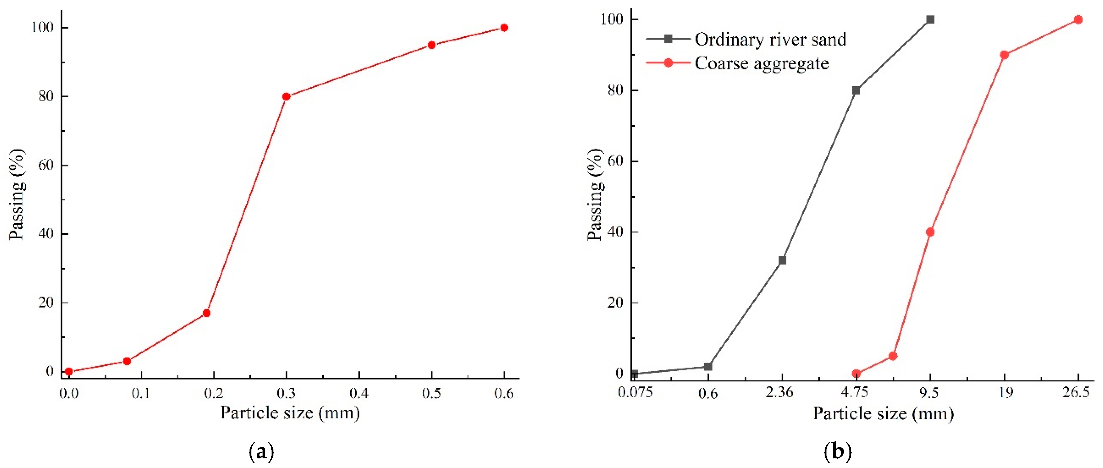
2.1. Raw Materials
2.2. Specimen Preparations
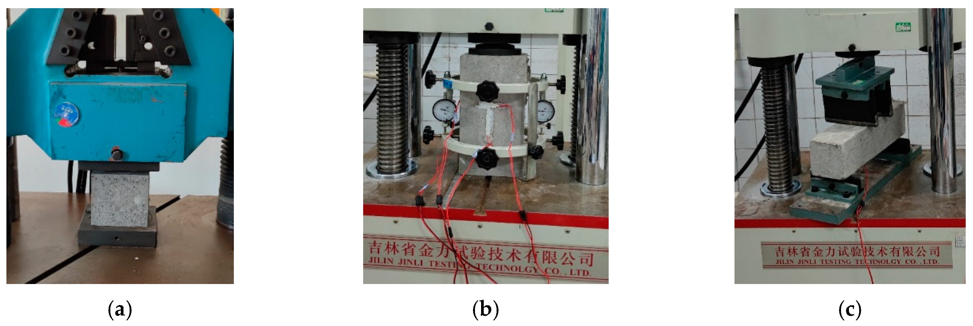
2.3. Test Program
2.3.1. Basic Mechanical Properties
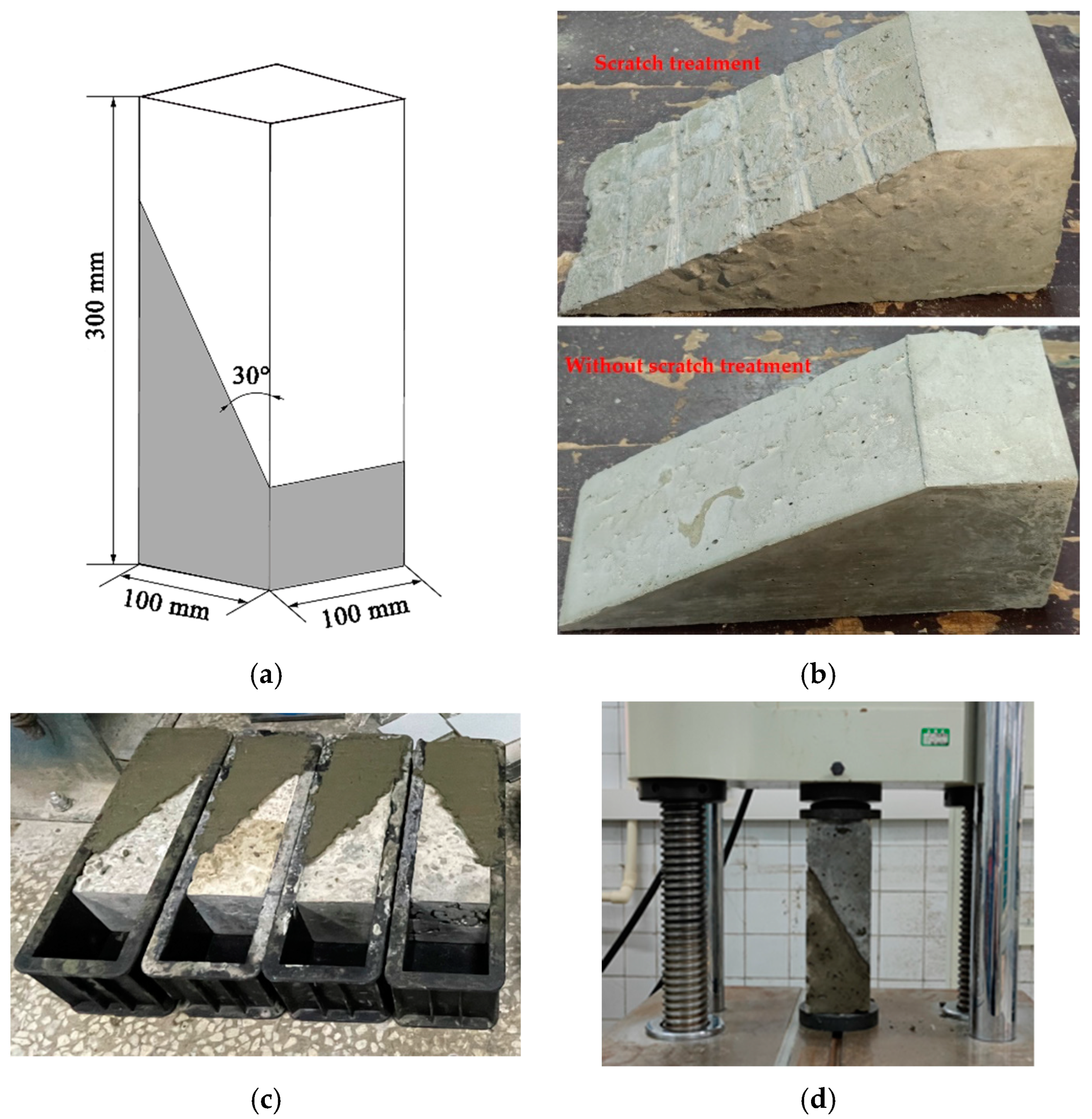
2.3.2. Slant Shear Test
- τn—shear stress (MPa);
- P—maximum applied compressive force (kN);
- A—cross-section angle (mm2);
- α—interface angle (30°).
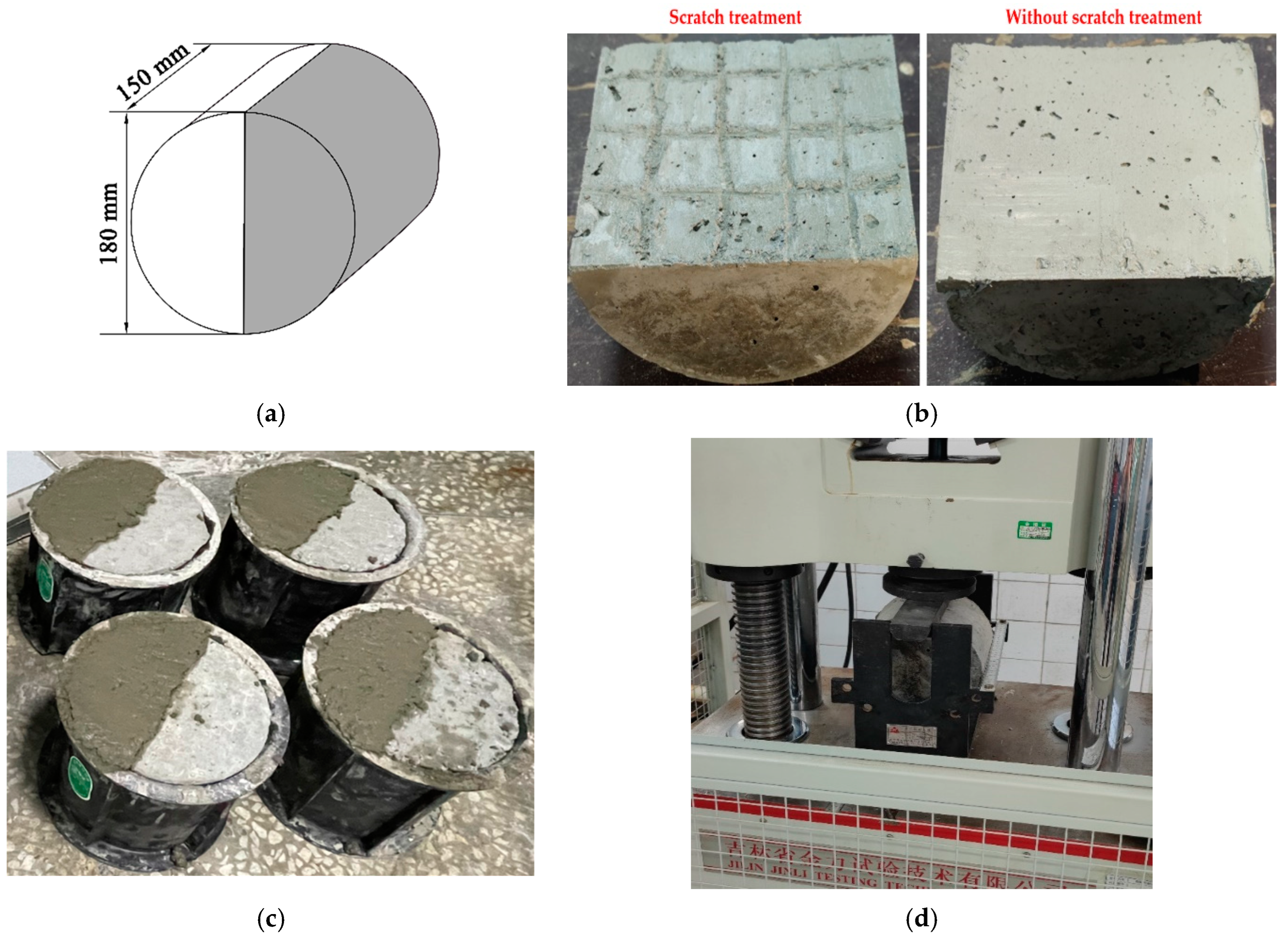
2.3.3. Split Tensile Test
- fs—split tensile strength (MPa);
- P—maximum applied load (kN);
- A—area of the bonded load (mm2).
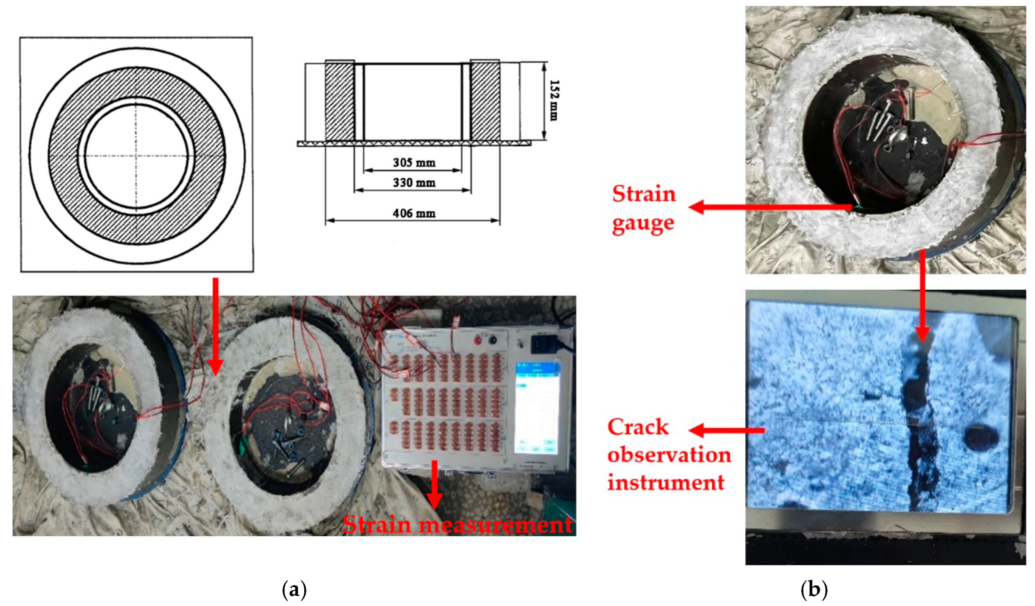
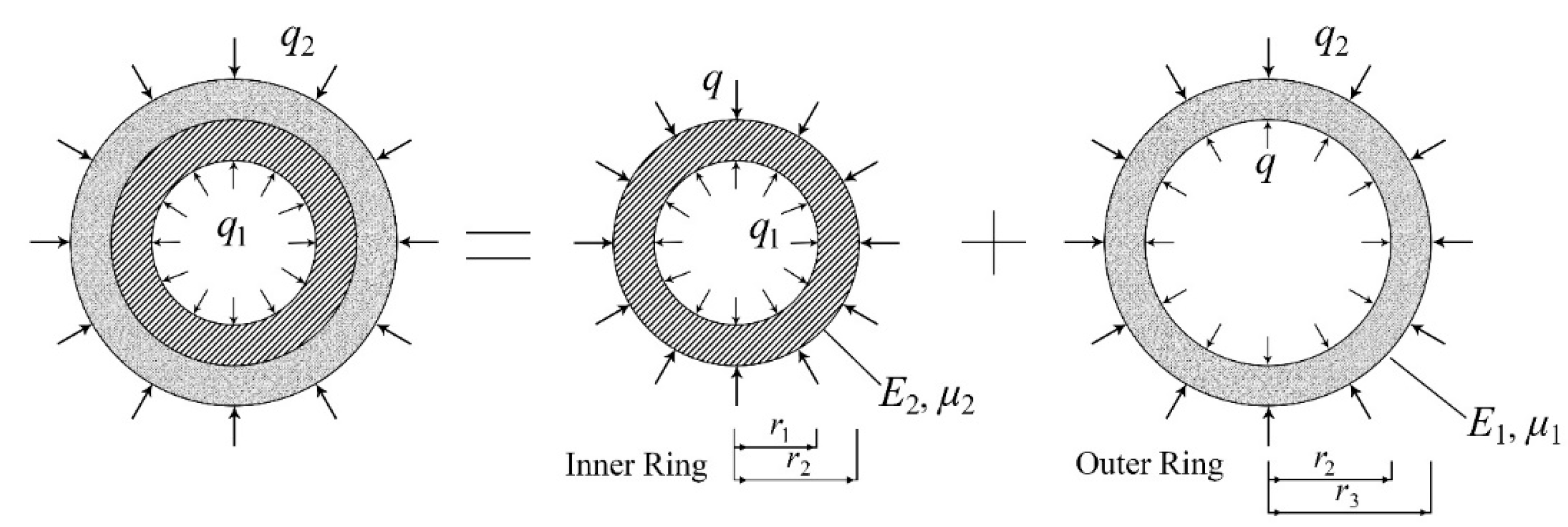
2.3.4. Restrained Shrinkage
- εnet—net strain (m/m);
- α—strain rate factor for each strain gauge on the test specimen ((m/m)/d1/2);
- t—elapsed time (d);
- k—regression constant.
- q—stress rate in each test specimen (MPa/d);
- G = 10.47 × 10⁶ psi (72.2 GPa);
- |αavg|—absolute value of the average strain rate factor for each test specimen ((m/m)/d1/2);
- tr—elapsed time at cracking or elapsed time when the test was terminated (d).
3. Results and Discussions
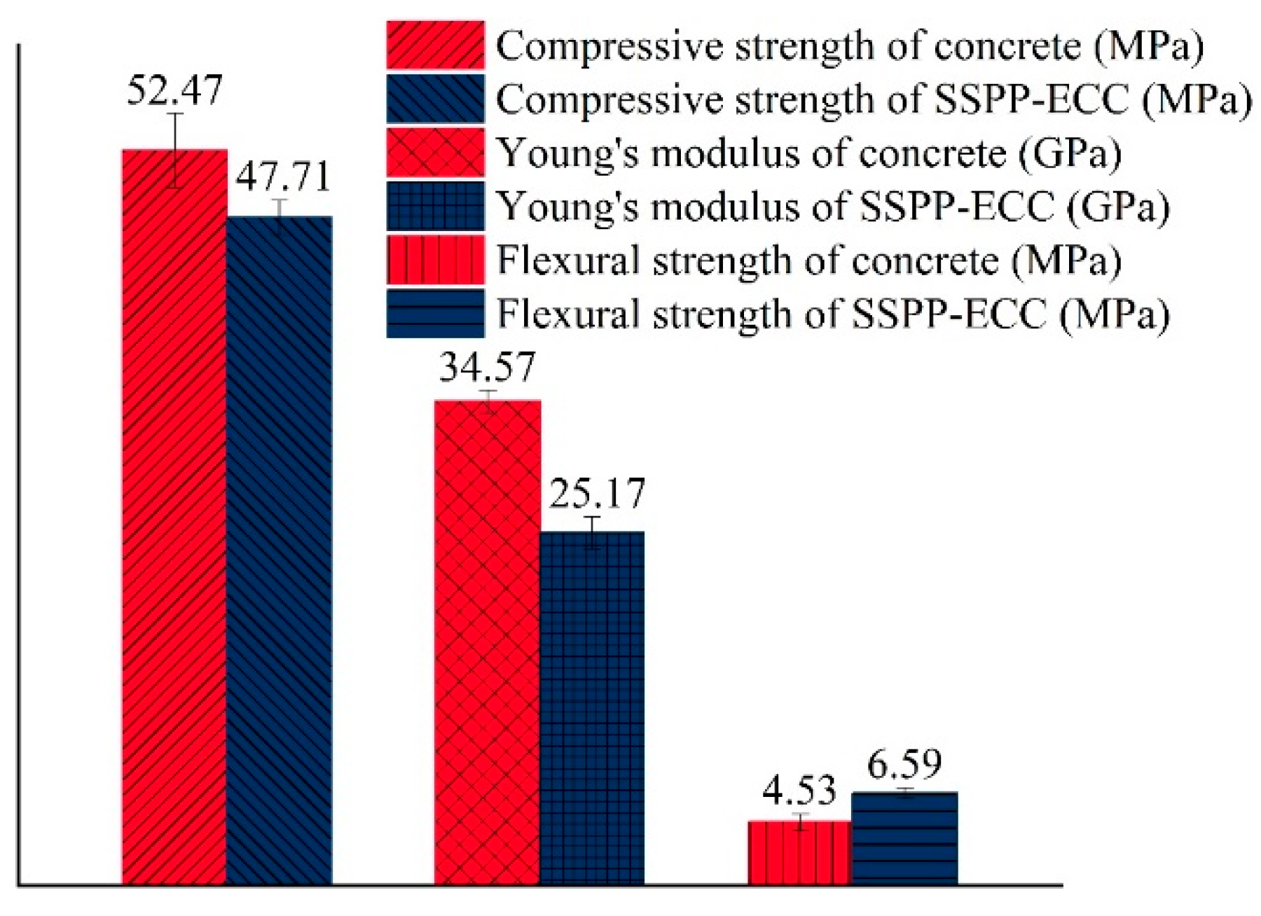
3.1. Basic Mechanical Properties Test Results
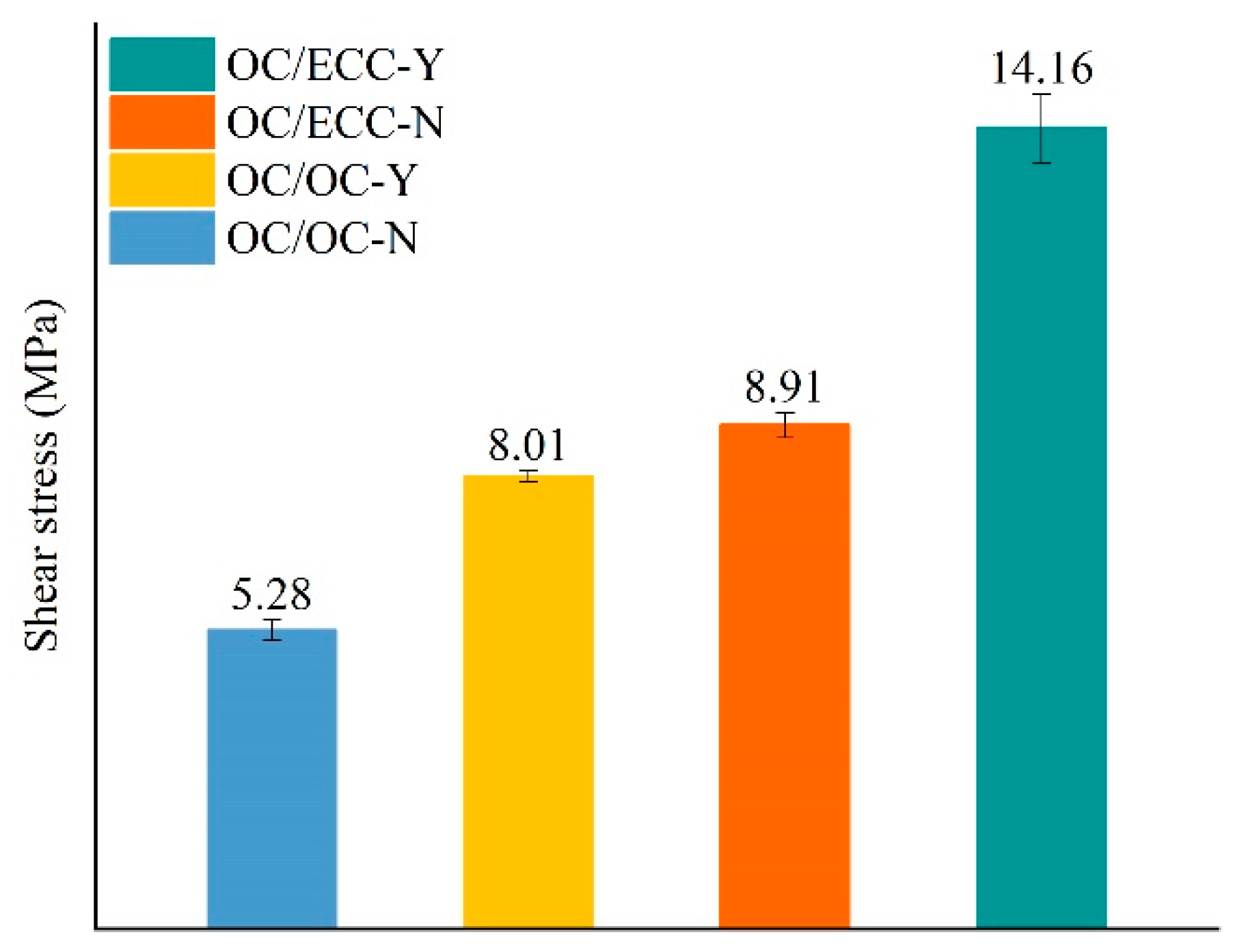
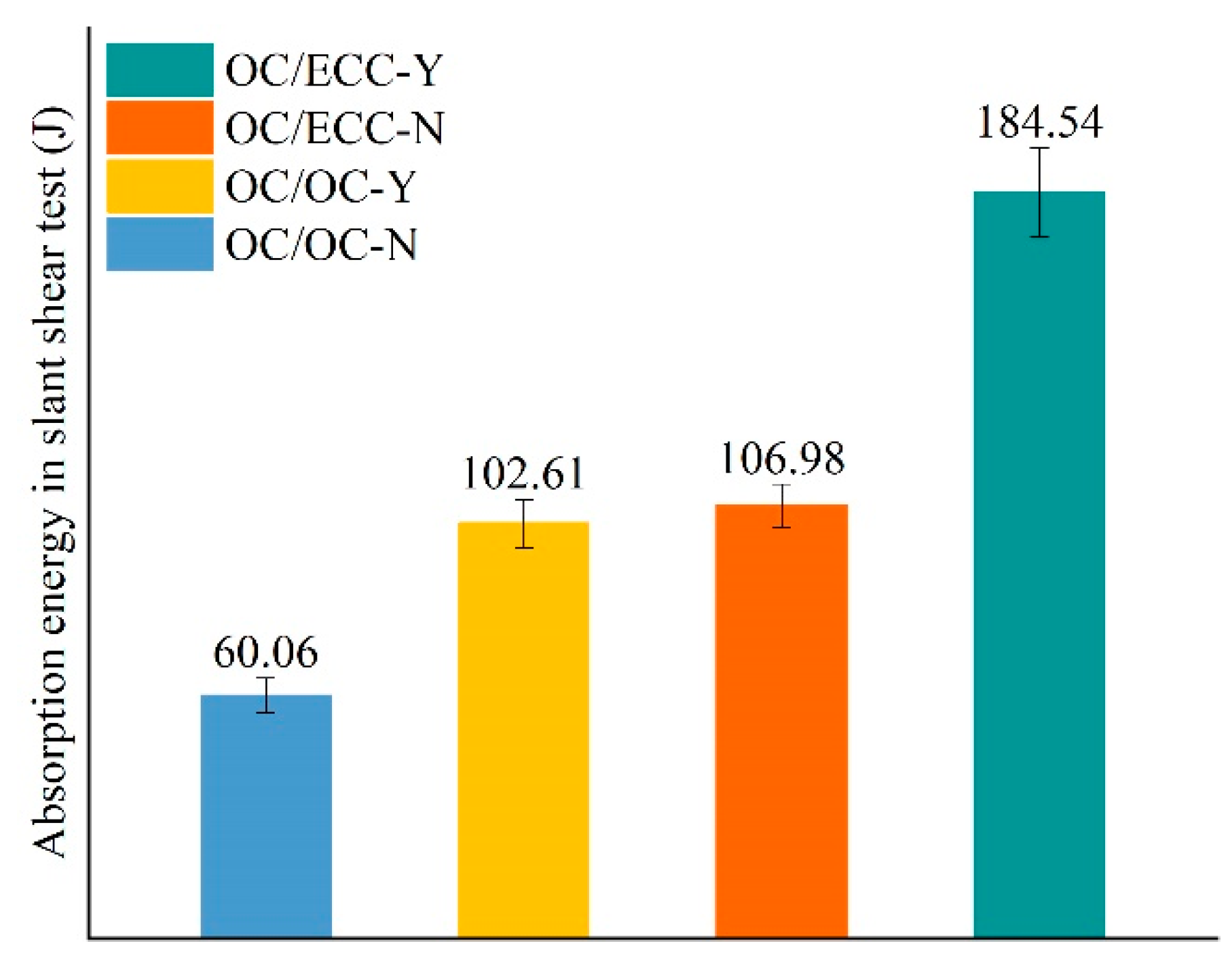
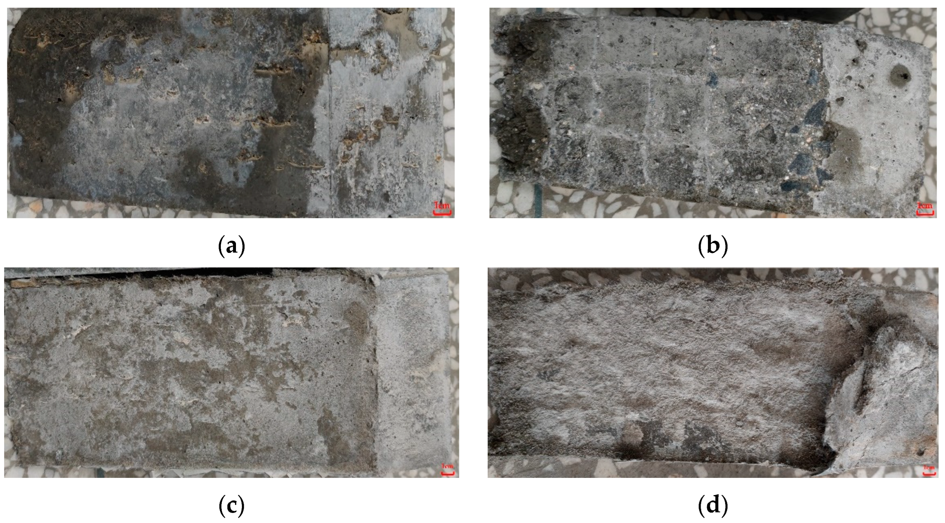
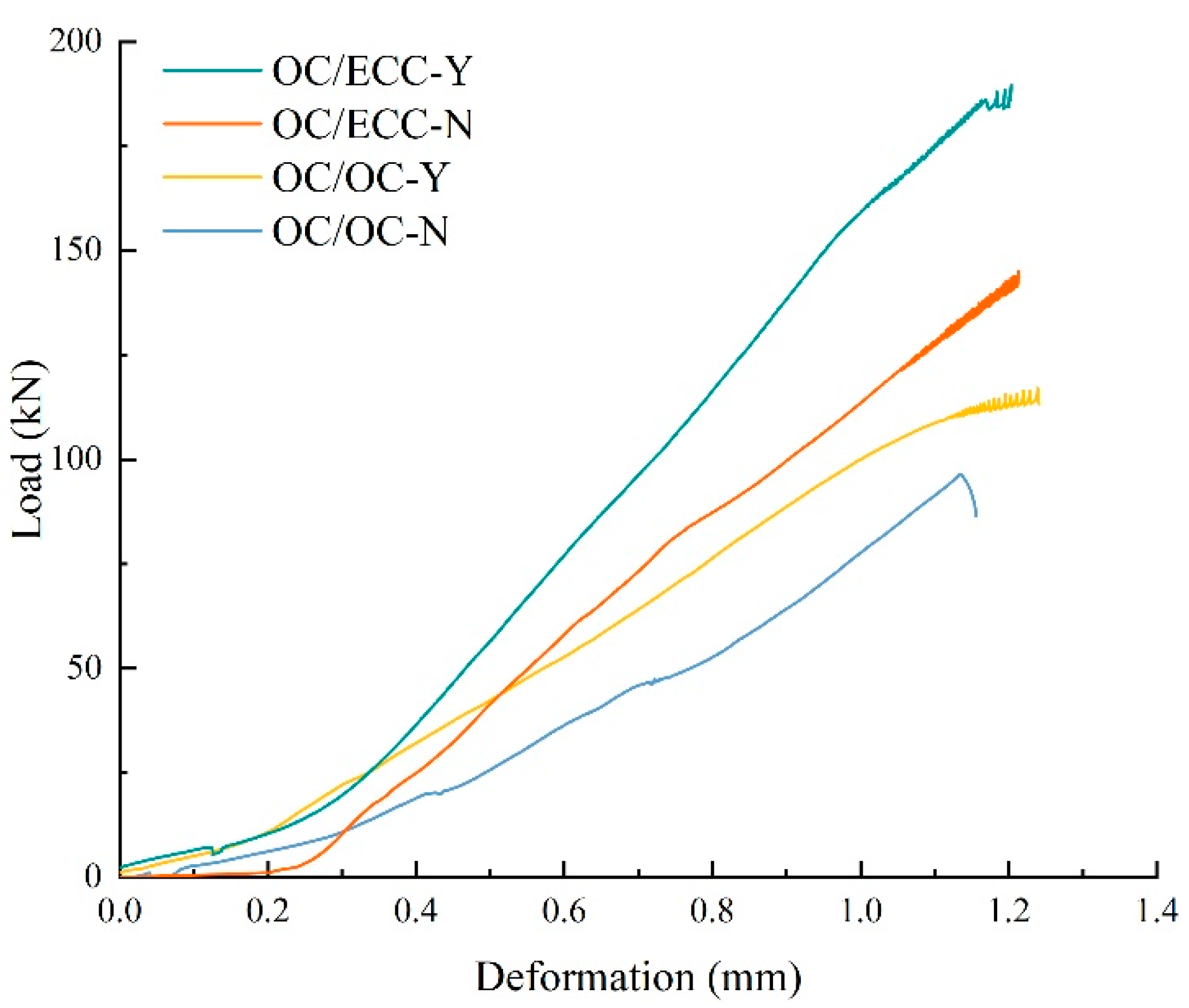
3.2. Slant Shear Test
3.3. Split Tensile Test
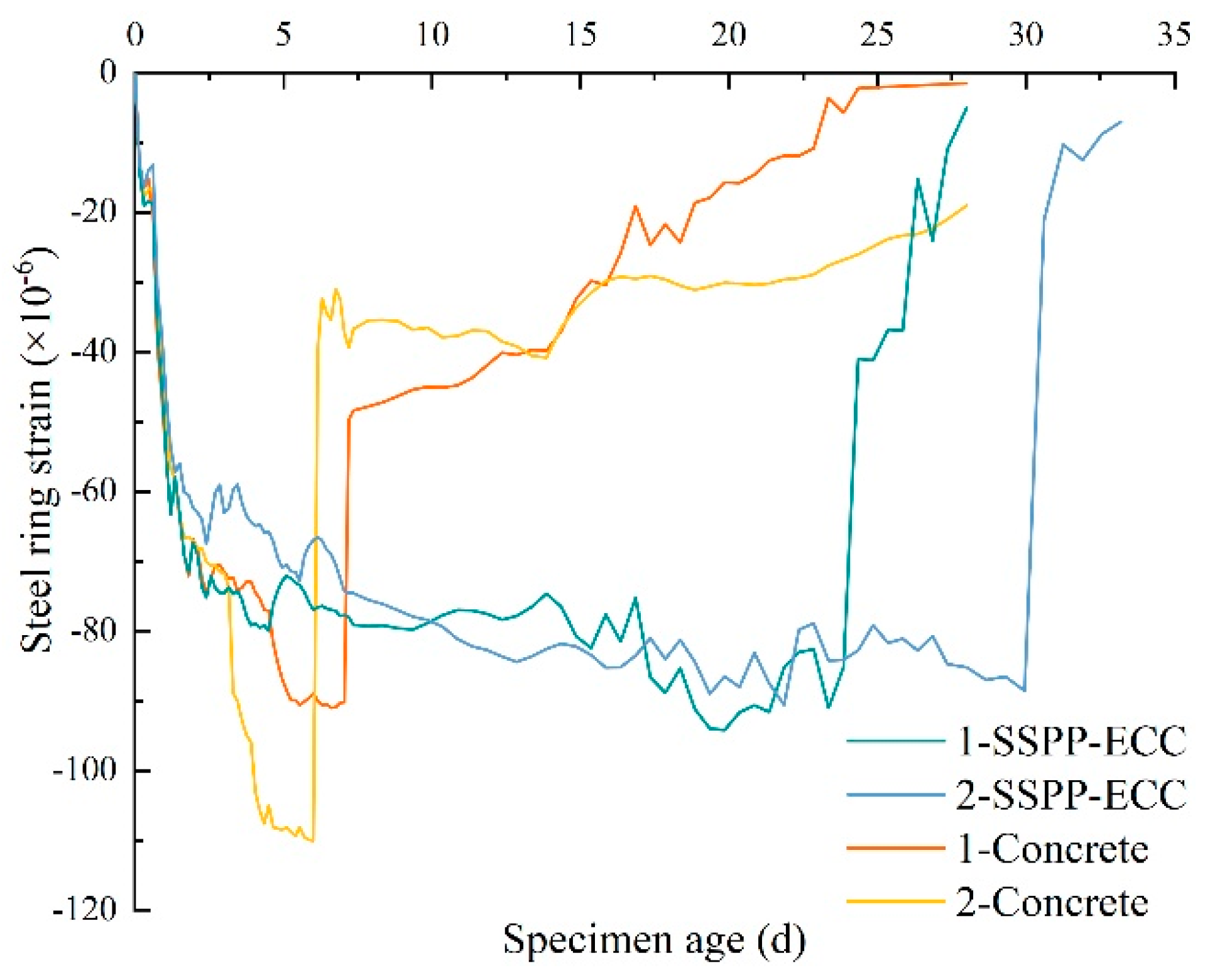
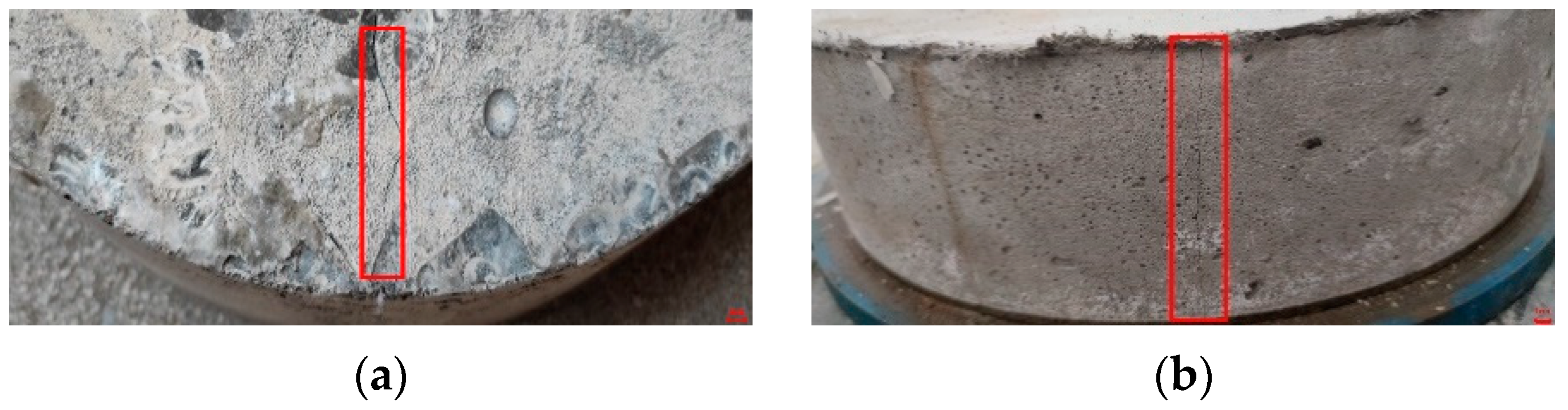
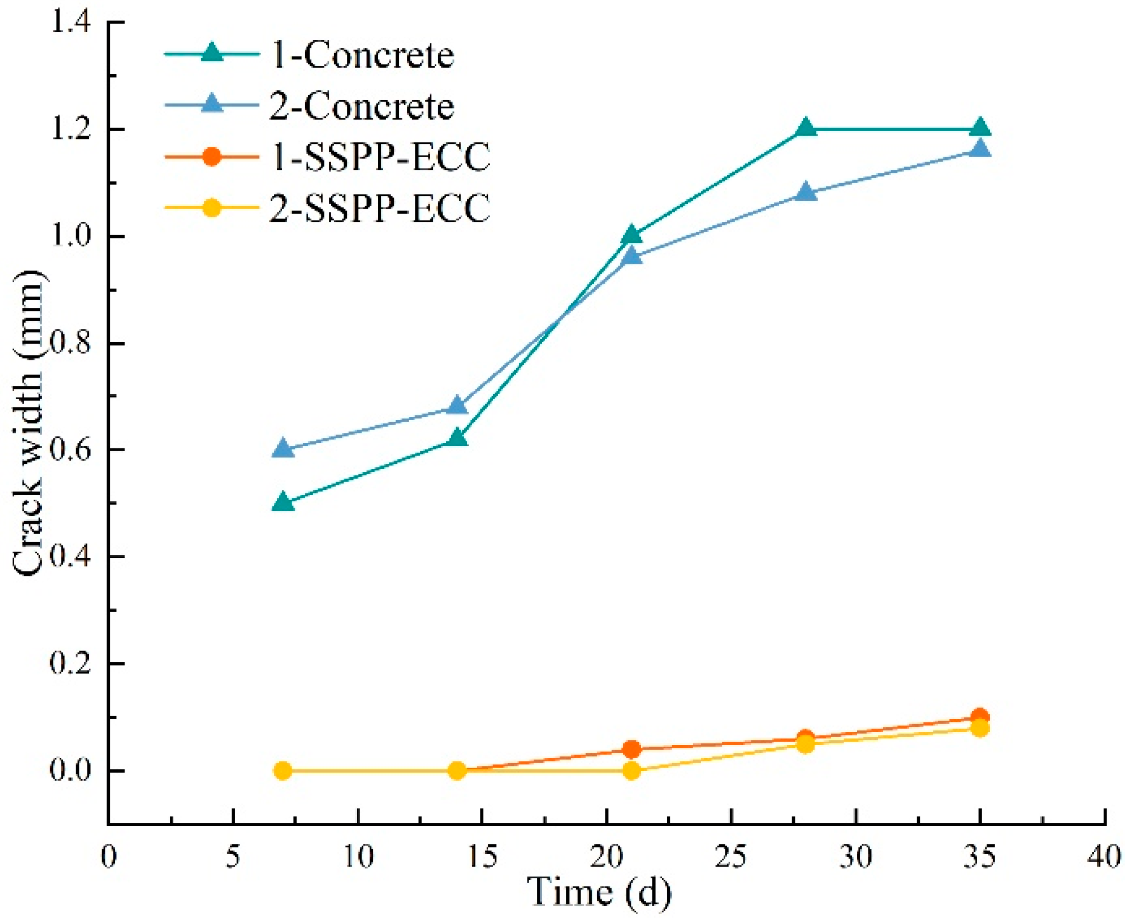
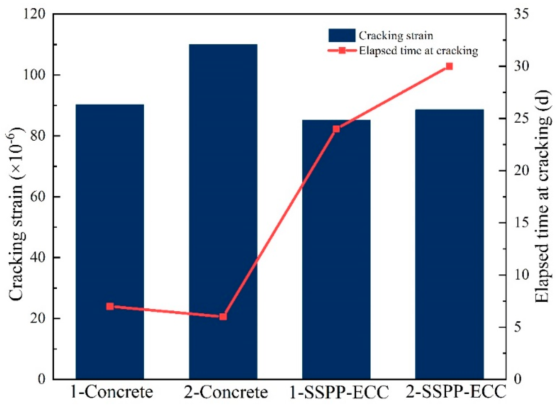
3.4. Restrained Shrinkage
- q—interface stress;
- E1—Young’s modulus of ordinary concrete/SSPP-ECC;
- E2—Young’s modulus of the steel ring;
- μ1—Poisson’s ratio of ordinary concrete/SSPP-ECC;
- μ2—steel ring Poisson’s ratio;
- σθ—outer ring tensile stress;
- εθ—inner ring shrinkage strain;
- εsh—outer ring shrinkage strain.
4. Conclusions
- The slant shear test results showed that interfacial scratch treatment provided a better enhancement effect on split tensile strength and using SSPP-ECC instead of ordinary concrete in shear stress provided more significant enhancement than a scratch treatment. Moreover, the damage status of OC/ECC-Y was no longer completely damaged along the bonding interface as in other specimens, which showed that OC/ECC-Y had an excellent shear resistance property.
- The split tensile test results showed that the interfacial scratch treatment provided an enhancement effect regarding split tensile strength, while the lifting effect was low relative to the shear stress; using SSPP-ECC instead of ordinary concrete provided a more significant enhancement in split tensile strength than a scratch treatment. The damage status of OC/ECC-Y was no longer showed complete damage along the bonding interface as in other specimens, which showed that OC/ECC-Y had excellent tensile resistance.
- The restrained shrinkage test showed that the average cracking age of SSPP-ECC was far longer than ordinary concrete, which showed that SSPP-ECC could significantly delay the cracking time. The shrinkage strain of SSPP-ECC was slightly lower than concrete, and its average stress rate confirmed SSPP-ECC as a low-cracking-risk material. Moreover, the crack width of SSPP-ECC was far lower than ordinary concrete, which confirmed SSPP-ECC had a powerful crack width control capacity.
- In summary, SSPP-ECC had a proficient bonding effect with ordinary concrete, which had stronger resistance in shear and tension. SSPP-ECC had better volume stability and substantial shrinkage cracking resistance. Thus, SSPP-ECC can be applied to the construction of a large area and low thickness of the leveling overlay in bridge pavement.
Author Contributions
Funding
Institutional Review Board Statement
Informed Consent Statement
Data Availability Statement
Acknowledgments
Conflicts of Interest
References
- Jin, W.; Zhao, Y.; Wang, W.; He, F. Performance Evaluation and Optimization of Waterproof Adhesive Layer for Concrete Bridge Deck in Seasonal Frozen Region Using AHP. Adv. Mater. Sci. Eng. 2021, 2021, 5555535. [Google Scholar] [CrossRef]
- Zhang, M.; Hao, P.; Men, G.; Liu, N.; Yuan, G. Research on the compatibility of waterproof layer materials and asphalt mixture for the steel bridge deck. Constr. Build. Mater. 2020, 269, 121346. [Google Scholar] [CrossRef]
- Castro, M. Structural design of asphalt pavement on concrete bridges. Can. J. Civil. Eng. 2004, 31, 695–702. [Google Scholar] [CrossRef]
- Rhee, J.; Kim, H.; Ock, C.; Choi, J. An investigation of the deterioration characteristics of concrete bridge decks with asphalt concrete in Korea. Ksce. J. Civ. Eng. 2018, 22, 613–621. [Google Scholar] [CrossRef]
- Fu, J.; Shen, A.; Zhang, H. Study on the Influence and Law of Waterproof System Design Factors on the Typical Stress of Bridge pavement. Coatings 2021, 11, 1540. [Google Scholar] [CrossRef]
- Guo, W.; Guo, X.; Wang, Z.; Li, Z. Investigation on Moisture Damage Prevention of a Spherical Hinge Structure of a Swivel Bridge. Coatings 2020, 10, 955. [Google Scholar] [CrossRef]
- Al-musawi, H.; Huang, H.; Benedetti, M.D.; Guadagnini, M.; Pilakoutas, K. Effect of shrinkage on rapid hardening plain and recycled steel fibre concrete overlays. Cement. Concr. Comp. 2022, 125, 104246. [Google Scholar] [CrossRef]
- Theine, Y.; Hart, H.; Drexel, M.; Hofstetter, G. Experimental Study of Strengthening an RC Bridge Deck by Adding a Concrete Overlay. Strain 2013, 49, 377–392. [Google Scholar]
- ACI 548.5R-16; Guide for Polymer Concrete Overlays. American Concrete Institute: Farmington Hills, MI, USA, 2016.
- CIQ China Inspection and Quarantine. JTG D60-2015; General Specifications for Design of Highway Bridges and Culverts; Standardization Administration of China: Beijing, China, 2015. (In Chinese) [Google Scholar]
- CIQ China Inspection and Quarantine. JTG/T 3650-2020; Technical Specifications for Construction of Highway Bridges and Culverts; Standardization Administration of China: Beijing, China, 2020. (In Chinese) [Google Scholar]
- CIQ China Inspection and Quarantine. DB51/T 1993—2015; Technical Specification for Composite Strengthening of Bridge Deck Paving; Standardization Administration of China: Beijing, China, 2015. (In Chinese) [Google Scholar]
- CIQ China Inspection and Quarantine. CJJ/T 279-2018; Technical Standard for Construction of Paving Asphalt Concrete Urban Bridge Deck; Standardization Administration of China: Beijing, China, 2018. (In Chinese) [Google Scholar]
- Orta, L.; Bartlett, F.M. Stresses Due to Restrained Shrinkage in Concrete Deck Overlays. Aci. Mater. J. 2014, 111, 701–710. [Google Scholar] [CrossRef]
- Okumus, P.; Arancibia, M.D. Sources, mitigation and implications of skew-related concrete deck cracks in girder bridges. Struct. Infrastruct. E 2021, 17, 1612–1625. [Google Scholar] [CrossRef]
- ElSafty, A.; Abdel-Mohti, A. Investigation of Likelihood of Cracking in Reinforced Concrete Bridge Decks. Int. J. Concr. Struct. Mater. 2013, 7, 79–93. [Google Scholar] [CrossRef] [Green Version]
- Shi, W.; Han, Z.; Yu, Y.; Luo, C.; Shan, J.; Wang, T. Case study of a SAP-CRC bridge deck in Lu-shan County, Henan, China. Struct. Concr. 2021, 22, 1523–1533. [Google Scholar] [CrossRef]
- Orta, L.; Bartlett, F.M. Sensitivity analysis of restrained shrinkage stresses of concrete deck overlays. Eng. Struct. 2020, 210, 110396. [Google Scholar] [CrossRef]
- Xu, Q.; Zhou, Q.; Medina, C.; Chang, G.K.; Rozycki, D.K. Experimental and numerical analysis of a waterproofing adhesive layer used on concrete-bridge decks. Int. J. Adhes. Adhes. 2009, 29, 525–534. [Google Scholar] [CrossRef]
- Freimann, T.; Heinlein, U. Pre-applied waterproofing membranes (Article). Beton.-Stahlbetonbau. 2018, 113, 368–384. [Google Scholar] [CrossRef]
- Li, V.C.; Wang, S.; Wu, C. Tensile strain-hardening behavior or polyvinyl alcohol engineered cementitious composite (PVA-ECC). Aci. Mater. J. 2001, 98, 483–492. [Google Scholar]
- Zhang, J.; Li, V.C. Monotonic and fatigue performance in bending of fiber-reinforced engineered cementitious composite in overlay system. Cement. Concr. Res. 2002, 32, 415–423. [Google Scholar] [CrossRef]
- Pan, Z.; Wu, C.; Liu, J.; Wang, W.; Liu, J. Study on mechanical properties of cost-effective polyvinyl alcohol engineered cementitious composites (PVA-ECC). Constr. Build. Mater. 2015, 78, 397–404. [Google Scholar] [CrossRef]
- Li, V.C.; Wu, C.; Wang, S.; Ogawa, A.; Saito, T. Interface tailoring for strain-hardening polyvinyl alcohol-engineered cementitious composite (PVA-ECC). Aci. Mater. J. 2002, 99, 463–472. [Google Scholar]
- Horikoshi, T.; Li, V.C.; Ogawa, A.; Saito, T.; Torigoe, S. Micromechanics-Based Durability Study of Polyvinyl Alcohol-Engineered Cementitious Composite. Aci. Mater. J. 2004, 101, 242–248. [Google Scholar]
- Zhou, Y.; Gong, G.; Huang, Y.; Chen, C.; Huang, D.; Chen, Z.; Guo, M. Feasibility of incorporating recycled fine aggregate in high performance green lightweight engineered cementitious composites. J. Clean. Prod. 2021, 280, 124445. [Google Scholar] [CrossRef]
- Xu, L.; Huang, B.; Dai, J. Development of Engineered Cementitious Composites (ECC) Using Artificial Fine Aggregates. Constr. Build. Mater. 2021, 305, 124742. [Google Scholar] [CrossRef]
- Pakravan, H.R.; Jamshidi, M.; Latifi, M. Performance of Fibers Embedded in a Cementitious Matrix. J. Appl. Polym. Sci. 2010, 116, 1247–1253. [Google Scholar] [CrossRef]
- Tian, J.; Wu, X.; Wang, W.; Hu, S.; Tan, X.; Du, Y.; Zheng, Y.; Sun, C. Experimental study and mechanics model of ECC-to-concrete bond interface under tensile loading. Compos Struct. 2022, 285, 115203. [Google Scholar]
- Tian, J.; Wu, X.; Zheng, Y.; Hu, S.; Du, Y.; Wang, W.; Sun, C.; Zhang, L. Investigation of interface shear properties and mechanical model between ECC and concrete. Constr. Build. Mater. 2019, 223, 12–27. [Google Scholar] [CrossRef]
- Huang, H.; Yuan, Y.; Zhang, W.; Gao, Z. Bond behavior between lightweight aggregate concrete and normal weight concrete based on split-tensile test. Constr. Build. Mater. 2019, 209, 306–314. [Google Scholar] [CrossRef]
- Gao, S.; Zhao, X.; Qiao, J.; Guo, Y.; Hu, G. Study on the bonding properties of Engineered Cementitious Composites (ECC) and existing concrete exposed to high temperature. Constr. Build. Mater. 2019, 196, 330–344. [Google Scholar] [CrossRef]
- Sahmaran, M.; Yücel, H.E.; Yildirim, G.; Al-Emam, M.; Lachemi, M. Investigation of the Bond between Concrete Substrate and ECC Overlays. J. Mater. Civil. Eng. 2014, 26, 167–174. [Google Scholar] [CrossRef]
- Zheng, Y.; Wang, W.; Brigham, J.C. Flexural behaviour of reinforced concrete beams strengthened with a composite reinforcement layer: BFRP grid and ECC. Constr. Build. Mater. 2016, 115, 424–437. [Google Scholar] [CrossRef] [Green Version]
- Guan, Y.; Yuan, H.; Ge, Z.; Huang, Y.; Li, S.; Sun, R. Flexural Properties of ECC-Concrete Composite Beam. Adv. Civ. Eng. Mater. 2018, 2018, 3138759. [Google Scholar] [CrossRef] [Green Version]
- Mohammed, B.S.; Aswin, M.; Beatty, W.H.; Hafiz, M. Longitudinal shear resistance of PVA-ECC composite slabs. Structures 2016, 5, 247–257. [Google Scholar] [CrossRef]
- Sui, L.; Luo, M.; Yu, K.; Li, P.; Zhou, Y.; Chen, C. Effect of engineered cementitious composite on the bond behavior between fiber-reinforced polymer and concrete. Compos. Struct. 2018, 184, 775–788. [Google Scholar] [CrossRef]
- Huang, X.; Ranade, R.; Ni, W.; Li, V.C. Development of green engineered cementitious composites using iron ore tailings as aggregates. Constr. Build. Mater. 2013, 44, 757–764. [Google Scholar] [CrossRef]
- Dan, M.; Huang, T.; Zhang, Y.; Lee, C.K. Mechanical behaviour of a polyvinyl alcohol fibre reinforced engineered cementitious composite (PVA-ECC) using local ingredients. Constr. Build. Mater. 2017, 141, 259–270. [Google Scholar]
- Guan, X.; Li, Y.; Liu, T.; Zhang, C.; Li, H.; Ou, J. An economical ultra-high ductile engineered cementitious composite with large amount of coarse river sand. Constr. Build. Mater. 2019, 201, 461–472. [Google Scholar] [CrossRef]
- Zhu, H.; Yu, K.; Li, V.C. Sprayable engineered cementitious composites (ECC) using calcined clay limestone cement (LC3) and PP fiber. Cement. Concr. Comp. 2021, 115, 103868. [Google Scholar] [CrossRef]
- Zhu, Z.; Tan, G.; Zhang, W.; Wu, C. Preliminary Analysis of the Ductility and Crack-Control Ability of Engineered Cementitious Composite with Superfine Sand and Polypropylene Fiber (SSPP-ECC). Materials 2020, 13, 2609. [Google Scholar] [CrossRef]
- Tan, G.; Zhu, Z.; Wang, W.; Wu, C.; Ou, J.; Cui, G.; Zhang, D. Flexural ductility and crack-controlling capacity of polypropylene fiber reinforced ECC thin sheet with waste superfine river sand based on acoustic emission analysis. Constr. Build. Mater. 2021, 277, 122321. [Google Scholar] [CrossRef]
- Tan, G.; Zhu, Z.; Wang, W.; He, X. A fractal-based approach for cracking characterization and whole process prediction exploration of PP fiber reinforced ECC containing sustainable ingredients. Constr. Build. Mater. 2022, 318, 126015. [Google Scholar] [CrossRef]
- CIQ China Inspection and Quarantine. JTG 3420—2020; Testing Methods of Cement and Concrete for Highway Engineering; Standardization Administration of China: Beijing, China, 2020. (In Chinese) [Google Scholar]
- ASTM Standard C882/C882M-13a; Standard Test Method for Bond Strength of Epoxy-Resin Systems Used with Concrete by Slant Shear. ASTM International: West Conshohocken, PA, USA, 2013.
- Kwak, H.G.; Seo, Y.J. Shrinkage cracking at interior supports of continuous pre-cast pre-stressed concrete girder bridges. Constr. Build. Mater. 2002, 16, 35–47. [Google Scholar] [CrossRef]
- Fazel, A.; Mohammad, H.; Mahdi, K.; Mohammad, S. Effect of calcium stearate and aluminum powder on free and restrained drying shrinkage, crack characteristic and mechanical properties of concrete. Cement. Concr. Comp. 2022, 125, 104276. [Google Scholar]
- Khan, I.; Xu, T.; Castel, A.; Gilbert, R.; Babaee, M. Risk of early age cracking in geopolymer concrete due to restrained shrinkage. Constr. Build. Mater. 2019, 229, 116840. [Google Scholar] [CrossRef]
- Darabi, M.K.; Huang, C.; Bazzaz, M.; Masad, E.A.; Little, D.N. Characterization and validation of the nonlinear viscoelastic-viscoplastic with hardening-relaxation constitutive relationship for asphalt mixtures. Constr. Build. Mater. 2019, 216, 648–660. [Google Scholar] [CrossRef]
- Bazzaz, M.; Darabi, M.K.; Little, D.N.; Garg, N. Effect of Evotherm-M1 on Properties of Asphaltic Materials Used at NAPMRC Testing Facility. J. Test. Eval. 2019, 48, 1–14. [Google Scholar] [CrossRef]
- Ozyildirim, H.C.; Nair, H.; Sharifi, M. Field Performance of Low-Cracking Concretes for the Closure Pours and Overlays of Bridge Decks. Transport. Res. Rec. 2020, 2674, 361–370. [Google Scholar] [CrossRef]
- Ceia, F.; Raposo, J.; Guerra, M.; Julio, E.; De Brito, J. Shear strength of recycled aggregate concrete to natural aggregate concrete interfaces. Constr. Build. Mater. 2016, 109, 139–145. [Google Scholar] [CrossRef]
- Zhang, J.; Yuan, G.; Wang, Z. Evaluation of shrinkage induced cracking performance of low shrinkage engineered cementitious composite by ring tests. Compos. Part. B-Eng. 2013, 52, 21–29. [Google Scholar] [CrossRef]


| Properties | Cement | Fly Ash |
|---|---|---|
| Specific gravity | 3.10 | 2.13 |
| Surface area ratio (m2/kg) | 370 | 420 |
| CaO (%) | 60.38 | 3.01 |
| SiO2 (%) | 21.11 | 50.37 |
| Al2O3 (%) | 6.04 | 27.62 |
| Fe2O3 (%) | 2.56 | 7.83 |
| MgO (%) | 1.08 | 1.85 |
| Loss on ignition (%) | 1.02 | 7.23 |
| Water ratio (%) | 0.11 | 0.81 |
| Diameter (μm) | Length (mm) | Density (g/cm3) | Young’s Modulus (GPa) | Nominal Strength (MPa) | Elongation at Break (%) |
|---|---|---|---|---|---|
| 30 | 12 | 0.91 | 3.5 | 500 | 20 |
| Type | Mix Proportion (kg/m3) | |||||||
|---|---|---|---|---|---|---|---|---|
| Cement | Fly Ash | Superfine River Sand | Ordinary River Sand | Coarse Aggregate | PP Fiber | Water | HRWR | |
| Concrete | 445 | —— | —— | 630 | 1220 | —— | 150 | 7 |
| SSPP-ECC | 520 | 520 | 520 | —— | —— | 18.2 | 312 | 10 |
| tcr (d) | S (MPa/d) | Potential for Cracking | Concrete | SSPP-ECC | ||
|---|---|---|---|---|---|---|
| 0 < tcr ≤ 7 | S ≥ 0.34 | High | tcr | S | tcr | S |
| 7 < tcr ≤ 14 | 0.17 ≤ S < 0.34 | Moderate–high | 6.5 | 0.595 | 27 | 0.073 |
| 14 < tcr ≤ 28 | 0.10 ≤ S < 0.17 | Moderate–low | ||||
| tcr > 28 | S < 0.10 | Low | ||||
| Type | Time (d) | εθ (×10−6) | q (MPa) | σθ (MPa) | εsh (×10−6) |
|---|---|---|---|---|---|
| Concrete | 7 | 100.100 | 3.064 | 11.930 | 642 |
| SSPP-ECC | 7 | 76.015 | 2.327 | 9.061 | 618 |
| 27 | 86.850 | 2.658 | 10.350 | 706 |
Publisher’s Note: MDPI stays neutral with regard to jurisdictional claims in published maps and institutional affiliations. |
© 2022 by the authors. Licensee MDPI, Basel, Switzerland. This article is an open access article distributed under the terms and conditions of the Creative Commons Attribution (CC BY) license (https://creativecommons.org/licenses/by/4.0/).
Share and Cite
Wan, F.; Zhu, Z.; Wang, W.; Tan, G.; Yang, R.; Zhang, Z. Preliminary Exploration of Economic Polypropylene-Fiber-Reinforced ECC with Superfine River Sand (SSPP-ECC) Applied to a Bridge Pavement Leveling Overlay. Materials 2022, 15, 2474. https://doi.org/10.3390/ma15072474
Wan F, Zhu Z, Wang W, Tan G, Yang R, Zhang Z. Preliminary Exploration of Economic Polypropylene-Fiber-Reinforced ECC with Superfine River Sand (SSPP-ECC) Applied to a Bridge Pavement Leveling Overlay. Materials. 2022; 15(7):2474. https://doi.org/10.3390/ma15072474
Chicago/Turabian StyleWan, Feihong, Zhiqing Zhu, Wensheng Wang, Guojin Tan, Runchao Yang, and Zhicong Zhang. 2022. "Preliminary Exploration of Economic Polypropylene-Fiber-Reinforced ECC with Superfine River Sand (SSPP-ECC) Applied to a Bridge Pavement Leveling Overlay" Materials 15, no. 7: 2474. https://doi.org/10.3390/ma15072474
APA StyleWan, F., Zhu, Z., Wang, W., Tan, G., Yang, R., & Zhang, Z. (2022). Preliminary Exploration of Economic Polypropylene-Fiber-Reinforced ECC with Superfine River Sand (SSPP-ECC) Applied to a Bridge Pavement Leveling Overlay. Materials, 15(7), 2474. https://doi.org/10.3390/ma15072474