
Characterization of Titanium Alloy Obtained by Powder Metallurgy

 ,
, 

 and
and
Abstract
:1. Introduction
2. Materials and Experimental Methods
2.1. Material Selection
- -
- Micronic hydride powder (TiH2) with particle size min. 99.9% <63 µm, water atomized produced by Chemetall GmbH (Frankfurt, Germany), as a basic metal matrix, having titanium min. 95%, hydrogen min. 3.8%, small amounts of Si, Mg, Ni, Al, Fe max. 0.1% for each of them;
- -
- Micronic manganese powder, type MN006020, Goodfellow company (Seoul, Korea) provenience, purity 99.5% used for improving the wear behavior in friction conditions due to its property to form a protective layer of oxide in contact with air [40];
- -
- Tin micronic powder, SN006020, produced by Goodfellow company (Tokyo, Japan); tin helps titanium in the grinding process and is a metal with low influence in the transformation temperature; it also behaves very well in friction conditions [41];
- -
- Zirconium nanometric powder, purchased from the Goodfellow company (Hamburg, Germany). Zirconium has the same atomic structure as titanium, being considered an excellent alloying element of titanium, with a good corrosion resistance and has influence on reducing the transformation temperature [36,42];
- -
- Graphite powder, 2N5 type from American Elements company (Los Angeles, California, USA), having 99.5% purity and low friction coefficient. Due to Van der Waals forces, graphite has a very good wear resistance, being an excellent dry lubricant, these being the reasons why it was added in the composition of the alloy [43];
- -
- Alumix powder Al 123, based on aluminum powder but with small amounts of 4.5% wt. Cu, 1.31% wt. Mg, 0.5% wt. Si, 0.10% Fe, 0.05% wt. Sn 2%.
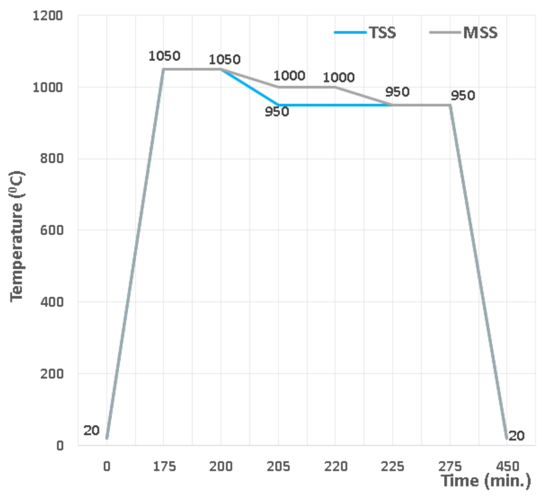
2.2. Experimental Procedure
- -
- sintering in two steps (TSS), with heating up to 1050 °C as the first stage, dwell time of 25 min and then the second sintering stage at 950 °C, with a dwell time of 75 min.
- -
- sintering in multiple steps (MSS), the first sintering level being at 1050 °C, with a dwell time of 25 min, the second sintering level at 1000 °C, with a dwell time of 20 min and the third sintering level at 950 °C, with a dwell time of 55 min.
2.3. Characterization Techniques
3. Experimental Results and Discussions
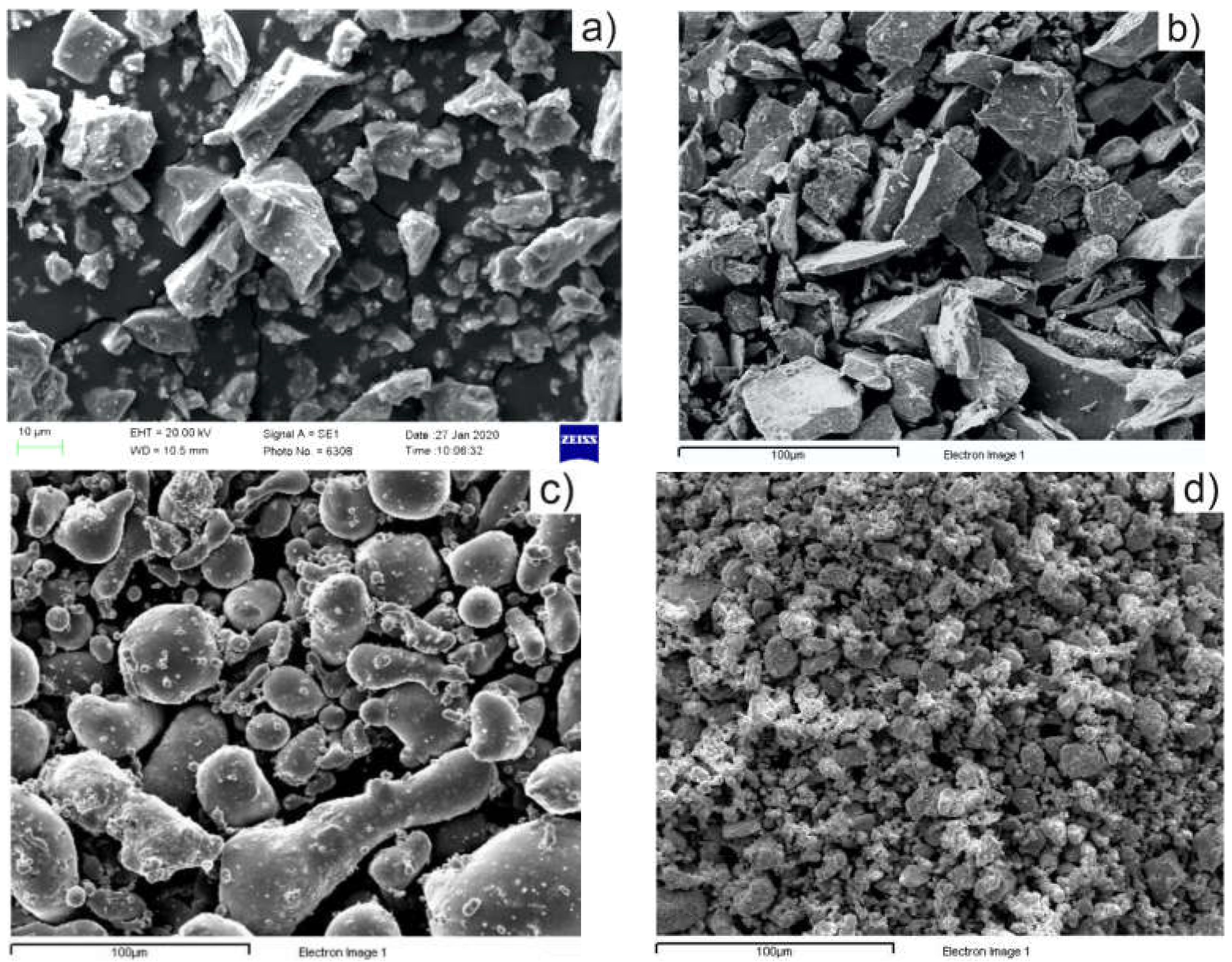
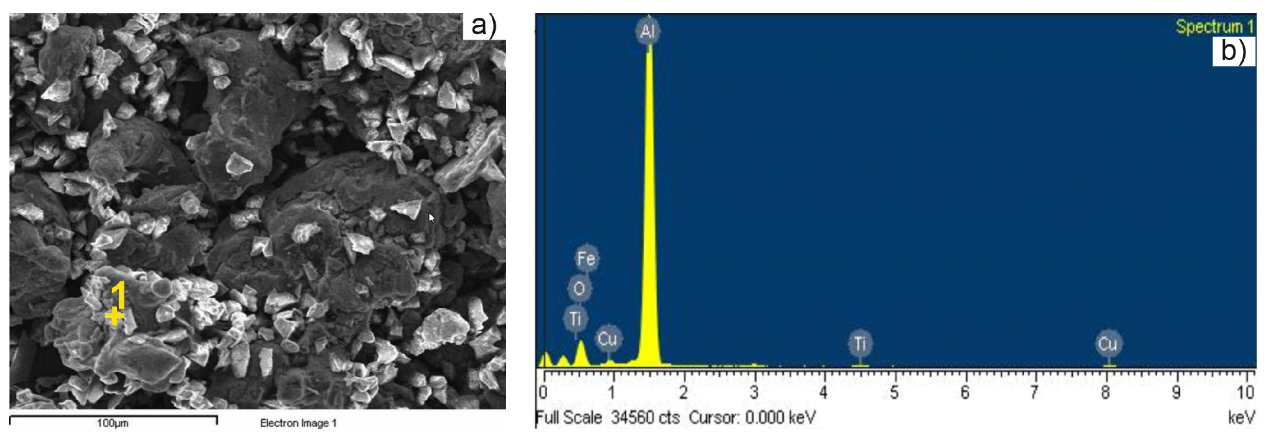
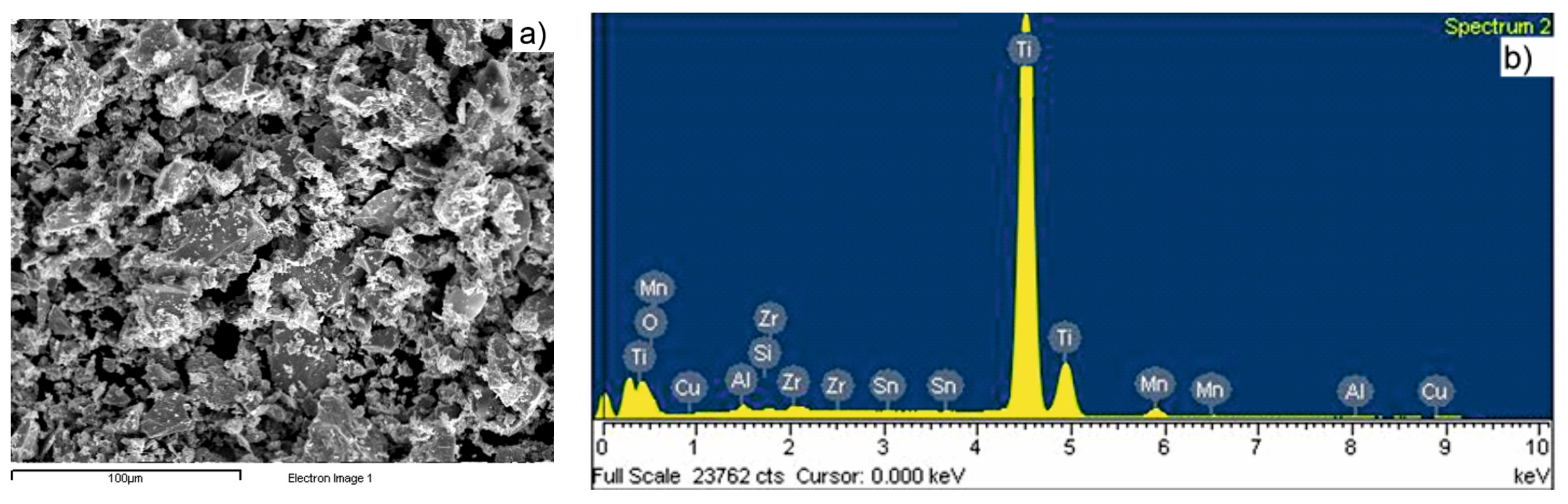
3.1. Precursor Powder Characterization
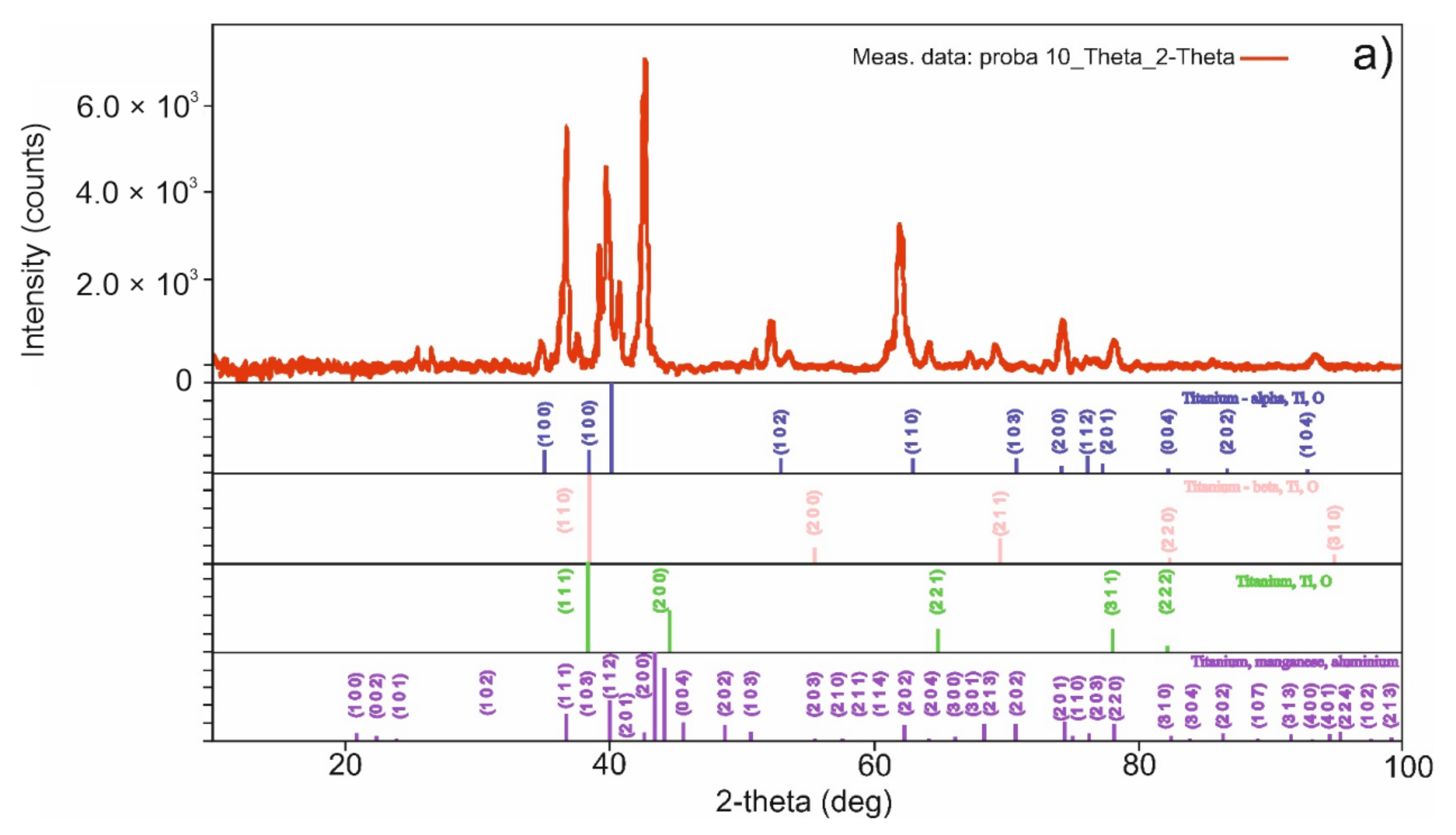
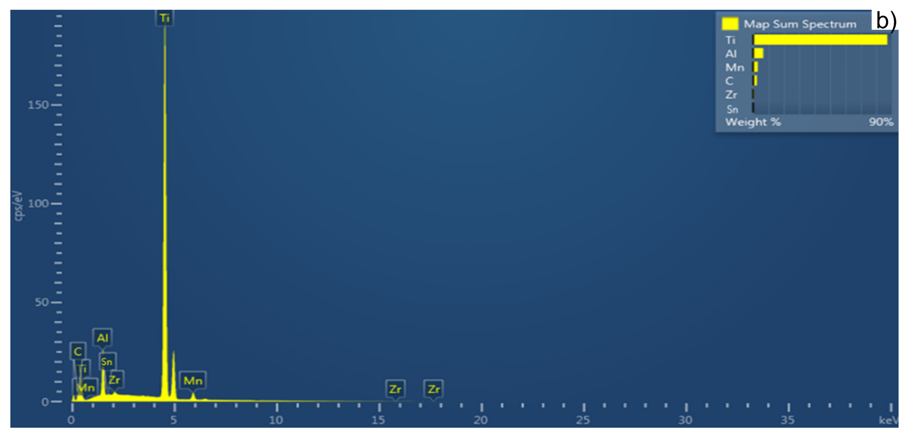
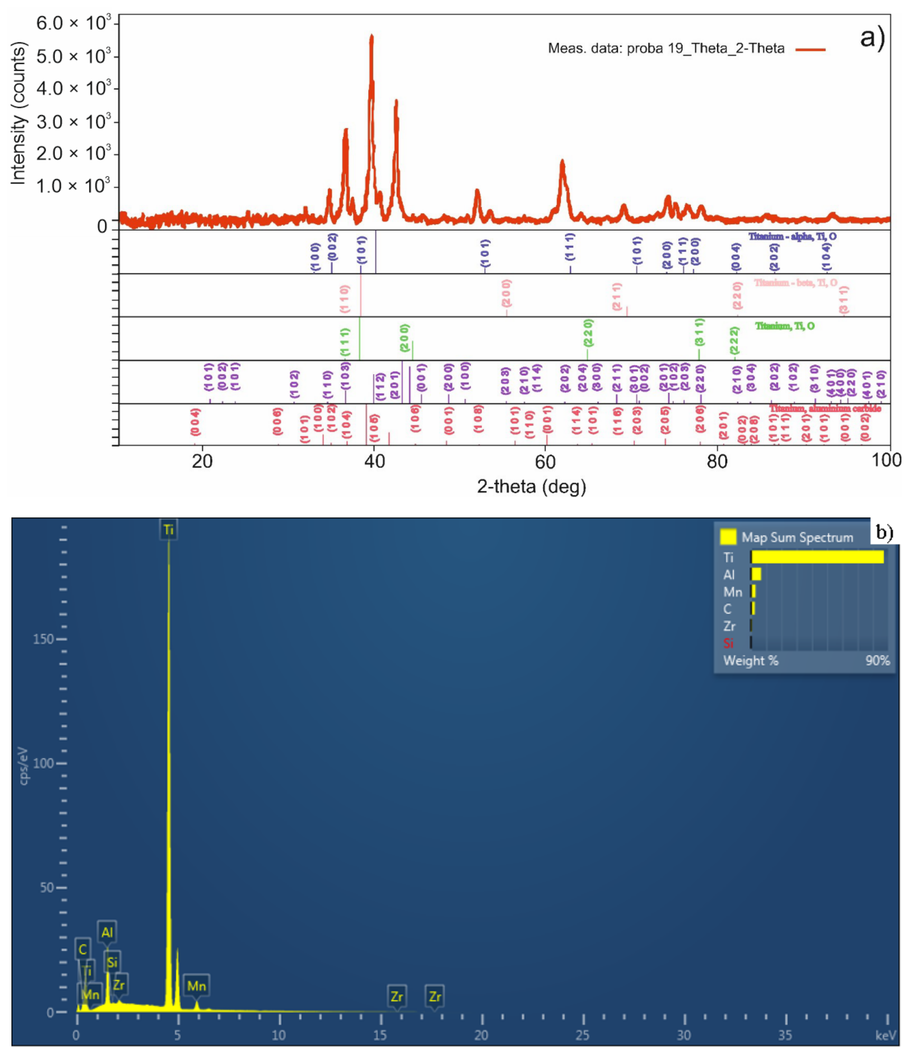
3.2. Sintered Pellet Characterization
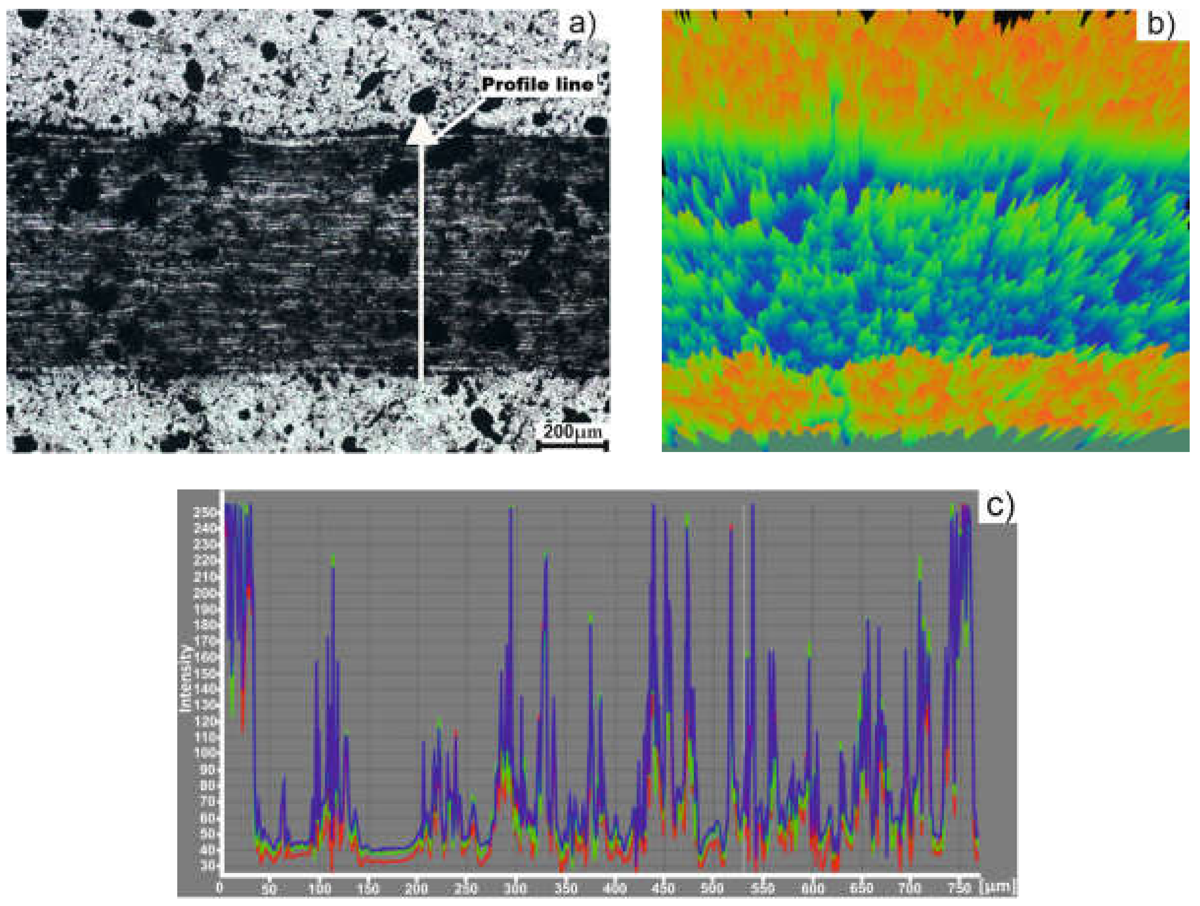
3.3. Tribological Behavior of Titanium Based Alloy
4. Conclusions
Author Contributions
Funding
Institutional Review Board Statement
Informed Consent Statement
Data Availability Statement
Acknowledgments
Conflicts of Interest
References
- Zhuravleva, K.; Bönisch, M.; Prashanth, K.G.; Hempel, U.; Helt, A.; Gemming, T.; Calin, M.; Scudino, S.; Schultz, L.; Eckert, J.; et al. Production of Porous β-Type Ti–40Nb Alloy for Biomedical Applications: Comparison of Selective Laser Melting and Hot Pressing. Materials 2013, 6, 5700–5712. [Google Scholar] [CrossRef] [PubMed]
- de Viteri, V.S.; Fuentes, E. Titanium and Titanium Alloys as Biomaterials. In Tribology—Fundamentals and Advancements; Gegner, J., Ed.; IntechOpen: London, UK, 2013; Available online: https://www.intechopen.com/chapters/44858 (accessed on 14 February 2022).
- Baltatu, M.S.; Vizureanu, P.; Sandu, A.V.; Florido-Suarez, N.; Saceleanu, M.V.; Mirza-Rosca, J.C. New Titanium Alloys, Promising Materials for Medical Devices. Materials 2021, 14, 5934. [Google Scholar] [CrossRef] [PubMed]
- Yu, C.; Peng, C.; Jones, M.I. Titanium Powder Sintering in a Graphite Furnace and Mechanical Properties of Sintered Parts. Metals 2017, 7, 67. [Google Scholar] [CrossRef] [Green Version]
- Paramore, J.D.; Fang, Z.Z.; Sun, P.; Koopman, M.; Chandran, K.S.R.; Dunstan, M. A powder metallurgy method for manufacturing Ti-6Al-4V with wrought-like microstructures and mechanical properties via hydrogen sintering and phase transformation (HSPT). Scripta Mater. 2015, 107, 103–106. [Google Scholar] [CrossRef] [Green Version]
- Chen, K.M.; Zhou, Y.; Li, X.X.; Zhang, Q.Y.; Wang, L.; Wang, S.Q. Investigation on wear characteristics of a titanium alloy/steel tribo-pair. Adv. Mater. Res. 2015, 65, 65–73. [Google Scholar] [CrossRef]
- Xu, X.; Nash, P.; Mangabhai, D. Characterization and Sintering of Armstrong Process Titanium Powder. JOM 2017, 69, 770–775. [Google Scholar] [CrossRef]
- Williams, J.C.; Boyer, R.R. Opportunities and Issues in the Application of Titanium Alloys for Aerospace Components. Metals 2020, 10, 705. [Google Scholar] [CrossRef]
- Exarchos, D.A.; Panagiota, T.D.; Tragazikis, I.K.; Dassios, K.G.; Zafeiropoulos, N.E.; Karabela, M.M.; de Crescenzo, C.; Karatza, D.; Musmarra, D.; Chianese, S.; et al. Development and Characterization of High Performance Shape Memory Alloy Coatings for Structural Aerospace Applications. Materials 2018, 11, 832. [Google Scholar] [CrossRef] [Green Version]
- Zhang, W.; Huang, Y.; Dai, W.; Jin, X.; Yin, C. A Fracture Analysis of Ti-10Mo-8V-1Fe-3.5Al Alloy Screws during Assembly. Materials 2016, 9, 852. [Google Scholar] [CrossRef] [Green Version]
- Tang, J.; Liu, D.; Zhang, X.; Du, D.; Yu, S. Effects of Plasma ZrN Metallurgy and Shot Peening Duplex Treatment on Fretting Wear and Fretting Fatigue Behavior of Ti6Al4V Alloy. Materials 2016, 9, 217. [Google Scholar] [CrossRef] [Green Version]
- Chanbi, D.; Ogam, E.; Amara, S.E.; Fellah, Z.E.A. Synthesis and Mechanical Characterization of Binary and Ternary Intermetallic Alloys Based on Fe-Ti-Al by Resonant Ultrasound Vibrational Methods. Materials 2018, 11, 746. [Google Scholar] [CrossRef] [PubMed] [Green Version]
- Bratan, S.; Stadnik, T.; Golovin, V. Evaluation of effectiveness of cutting fluids for belt grinding of long-length products of titanium alloys. Mater. Today Proc. 2021, 38, 2013–2018. [Google Scholar] [CrossRef]
- Deepalaxmi, R.; Rajini, V. Electromechanical characterization of titanium-dioxide-filled SiR-EPDM blends. Polym. Polym. Compos. 2021, 29, 311–322. [Google Scholar] [CrossRef]
- Schauerte, O. Titanium in automotive production. Adv. Eng. Mater. 2003, 5, 411–418. [Google Scholar] [CrossRef]
- Imam, M.A.; Froes, F.H.; Dring, K.F. Cost Affordable Developments in Titanium Technology and Applications. Key Eng. Mater. 2010, 436, 1–11. [Google Scholar] [CrossRef]
- Boyer, R.B. Attributes, characteristics, and applications of titanium and its alloys. JOM 2010, 62, 35–43. [Google Scholar] [CrossRef]
- Fuji, H.; Takahashi, K.; Yamashita, Y. Application of Titanium and Its Alloys for Automobile Parts. Nippon Steel Tech. Rep. 2003, 38, 70–75. [Google Scholar]
- Peng, Q.; Yang, B.; Friedrich, B. Porous Titanium Parts Fabricated by Sintering of TiH2 and Ti Powder Mixtures. J. Mater. Eng. Perform. 2018, 27, 228–242. [Google Scholar] [CrossRef]
- Ivasishin, O.M.; Savvakin, D.G.; Oryshych, D.V.; Stasiuk, O.O.; Yuanyuan, L. Hydride Approach in Blended Elemental Powder Metallurgy of Beta Titanium Alloys. MATEC Web Conf. 2020, 321, 03009. [Google Scholar] [CrossRef]
- Chen, Q.; Zhang, J.; Huang, A.; Wei, P. Study on Wear Resistance of Ti-6Al-4V Alloy Composite Coating Prepared by Laser Alloying. Appl. Sci. 2021, 11, 446. [Google Scholar] [CrossRef]
- Kaur, S.; Ghadirinejad, K.; Oskouei, R.H. An Overview on the Tribological Performance of Titanium Alloys with Surface Modifications for Biomedical Applications. Lubricants 2019, 7, 65. [Google Scholar] [CrossRef] [Green Version]
- Bodunrin, M.O.; Chown, L.H.; Omotoyinbo, J.A. Development of low-cost titanium alloys: A chronicle of challenges and opportunities. Mater. Today Proc. 2021, 38, 564–569. [Google Scholar] [CrossRef]
- Zhao, Q.; Yang, F.; Torrens, R.; Bolzoni, L. Comparison of hot deformation behaviour and microstructural evolution for Ti-5Al-5V-5Mo-3Cr alloys prepared by powder metallurgy and ingot metallurgy approaches. Mater. Des. 2019, 169, 107682. [Google Scholar] [CrossRef]
- Sharma, B.A.; Vajpai, S.K.; Ameyama, K. An Efficient Powder Metallurgy Processing Route to Prepare High-Performance _-Ti–Nb Alloys Using Pure Titanium and Titanium Hydride Powders. Metals 2018, 8, 516. [Google Scholar] [CrossRef] [Green Version]
- Dehghan-Manshadi, A.; Bermingham, M.J.; Dargusch, M.S.; StJohn, D.H.; Qian, M. Metal injection moulding of titanium and titanium alloys: Challenges and recent development. Powder Technol. 2017, 319, 289–301. [Google Scholar] [CrossRef] [Green Version]
- Vicente, F.B.; Correa, D.R.N.; Donato, T.A.G.; Arana-Chavez, V.E.; Buzalaf, M.A.R.; Grandini, R.C. The Influence of Small Quantities of Oxygen in the Structure, Microstructure, Hardness, Elasticity Modulus and Cytocompatibility of Ti-Zr Alloys for Dental Applications. Materials 2014, 7, 542–553. [Google Scholar] [CrossRef]
- Mishchenko, O.; Ovchynnykov, O.; Kapustian, O.; Pogorielov, M. New Zr-Ti-Nb Alloy for Medical Application: Development, Chemical and Mechanical Properties, and Biocompatibility. Materials 2020, 13, 1306. [Google Scholar] [CrossRef] [Green Version]
- Rabadiaa, C.D.; Liub, Y.J.; Zhaoc, C.H.; Wanga, J.C.; Jaweda, S.F.; Wang, L.Q.; Chene, L.Y.; Suna, H.; Zhanga, L.C. Improved trade-off between strength and plasticity in titanium based metastable beta type Ti-Zr-Fe-Sn alloys. Mater. Sci. Eng. A 2019, 766, 138340. [Google Scholar] [CrossRef]
- Lu, X.; Zhao, G.; Zhou, J.; Zhang, C.; Yu, J. Microstructure and Mechanical Properties of the As-Cast and As-Homogenized Mg-Zn-Sn-Mn-Ca Alloy Fabricated by Semicontinuous Casting. Materials 2018, 11, 703. [Google Scholar] [CrossRef] [Green Version]
- Gázquez, M.J.; Bolívar, J.P.; Garcia-Tenorio, R.; Vaca, F. A Review of the Production Cycle of Titanium Dioxide Pigment. Mater. Sci. Appl. 2014, 5, 441–458. [Google Scholar] [CrossRef] [Green Version]
- Wang, H.; Wang, S.; Gao, P.; Li, C.H. Microstructure and mechanical properties of a novel near-α titanium alloy Ti6.0Al4.5Cr1.5Mn. Adv. Mater. Res. 2016, 67, 170–174. [Google Scholar] [CrossRef]
- Salvetr, P.; Školáková, A.; Hudrisier, C.; Novák, P.; Vojtech, D. Reactive Sintering Mechanism and Phase Formationin Ni-Ti-Al Powder Mixture During Heating. Materials 2018, 11, 689. [Google Scholar] [CrossRef] [PubMed] [Green Version]
- Muthuchamy, A.; Annamalai, A.R.; Acharyya, S.G.; Nagaraju, N.; Agrawal, D.K. Microstructural and Electrochemical behaviour of Aluminium Alloy Composites Produced Using Different Sintering Techniques. Mater. Res. 2018, 21. [Google Scholar] [CrossRef] [Green Version]
- Markovsky, P.E.; Ikeda, M.; Ueda, M.; Bondarchuk, V.I. Microstructure and Mechanical Properties of a New Ti–1.5Al–1Fe–7.2Cr Alloy Produced with Conventional Cast and Wrought Approach. Metallofiz. Noveishie Tekhnol. 2019, 41, 1315–1329. [Google Scholar] [CrossRef]
- Luz, T.; de Oliveira, J.H.; Diniz, E. Production of Ti-Zr Alloy by Powder Metallurgy; SAE Technical Paper; SAE International: Warrendale, PA, USA, 2013; Paper Numbers: 2013-36-0388. [Google Scholar] [CrossRef]
- Sun, J.; Zhao, J.; Huang, Z.; Yan, K.; Chen, F.; Jian, Y.; Yang, H.; Bo, L. Preparation and properties of multilayer graphene reinforced binderless TiC nanocomposite cemented carbide through two-step sintering. Mater. Des. 2020, 188, 108495. [Google Scholar] [CrossRef]
- Moravcikova-Gouvea, L.; Moravcik, I.; Omasta, M.; Veselý, J.; Cizeka, J.; Minárik, P.; Cupera, J.; Záděr, A.; Jan, V.; Dlouhy, I. High-strength Al0.2Co1.5CrFeNi1.5Ti high-entropy alloy produced by powder metallurgy and casting: A comparison of microstructures, mechanical and tribological properties. Mater. Charact. 2020, 159, 110046. [Google Scholar] [CrossRef]
- Pascu, C.I.; Gheorghe, S.; Dumitru, I.; Nicolicescu, C. Aspects about Sintering Behaviour of a Titanium Hydride Powder Based Alloy Used for Automotive Components. Appl. Mech. Mater. 2016, 823, 467–472. [Google Scholar] [CrossRef]
- Alshammari, Y.; Bolzoni, L.; Yang, F. Mechanical properties and microstructure of Ti-Mn alloys produced via powder metallurgy for biomedical applications. J. Mech. Behav. Biomed. Mater. 2019, 91, 391–397. [Google Scholar] [CrossRef]
- Budinski, K.G.; Budimski, M. Engineering Materials: Properties and Selection, 9th ed.; Prentice Hall Publisher: New York, NY, USA, 2009. [Google Scholar]
- Hattal, A.; Chauveau, T.; Djemai, M.; Fouchet, J.J.; Bacroix, B.; Dirras, G. Effect of nano-yttria stabilized zirconia addition on the microstructure and mechanical properties of Ti6Al4V parts manufactured by selective laser melting. Mater. Des. 2019, 180, 107909. [Google Scholar] [CrossRef]
- Swee, H.T.; Thampuran, R.; Goh, J.; Hong, C. Titanium-Graphite Sintered Composite Material with Improved Wear Resistance and Low Coefficient of Friction. U.S. Patent DE19641023A1, 7 October 1995. [Google Scholar]
- Kaszuba, M.; McKnight, D.; Connah, M.T.; McNeil-Watson, F.K.; Nobbmann, U. Measuring sub nanometre sizes using dynamic light scattering. J. Nanopart. Res. 2008, 10, 823. [Google Scholar] [CrossRef] [Green Version]
- Lutjering, G.; Williams, J.C. Titanium; Springer: Berlin/Heidelberg, Germany, 2003. [Google Scholar]
- Cascadan, D.; Grandini, C.R. Effect of Oxygen in the Structure, Microstructure and Mechanical Properties of Ti-xNi (x = 5, 10, 15 and 20 wt%) Alloys. Metals 2020, 10, 1424. [Google Scholar] [CrossRef]
- Pascu, C.I.; Gheorghe, S.; Rotaru, A.; Nicolicescu, C.; Cioatera, N.; Roșca, A.S.; Sarbu, D.; Rotaru, P. Ti-based composite materials with enhanced thermal and mechanical properties. Ceram. Int. 2020, 46, 29358–29372. [Google Scholar] [CrossRef]
- Revankar, G.D.; Shetty, R.J.; Rao, S.S.; Gaitonde, V.N. Wear resistance enhancement of titanium alloy (Ti–6Al–4V) by ball burnishing process. J. Mater. Res. Tech. 2017, 6, 13–32. [Google Scholar] [CrossRef] [Green Version]


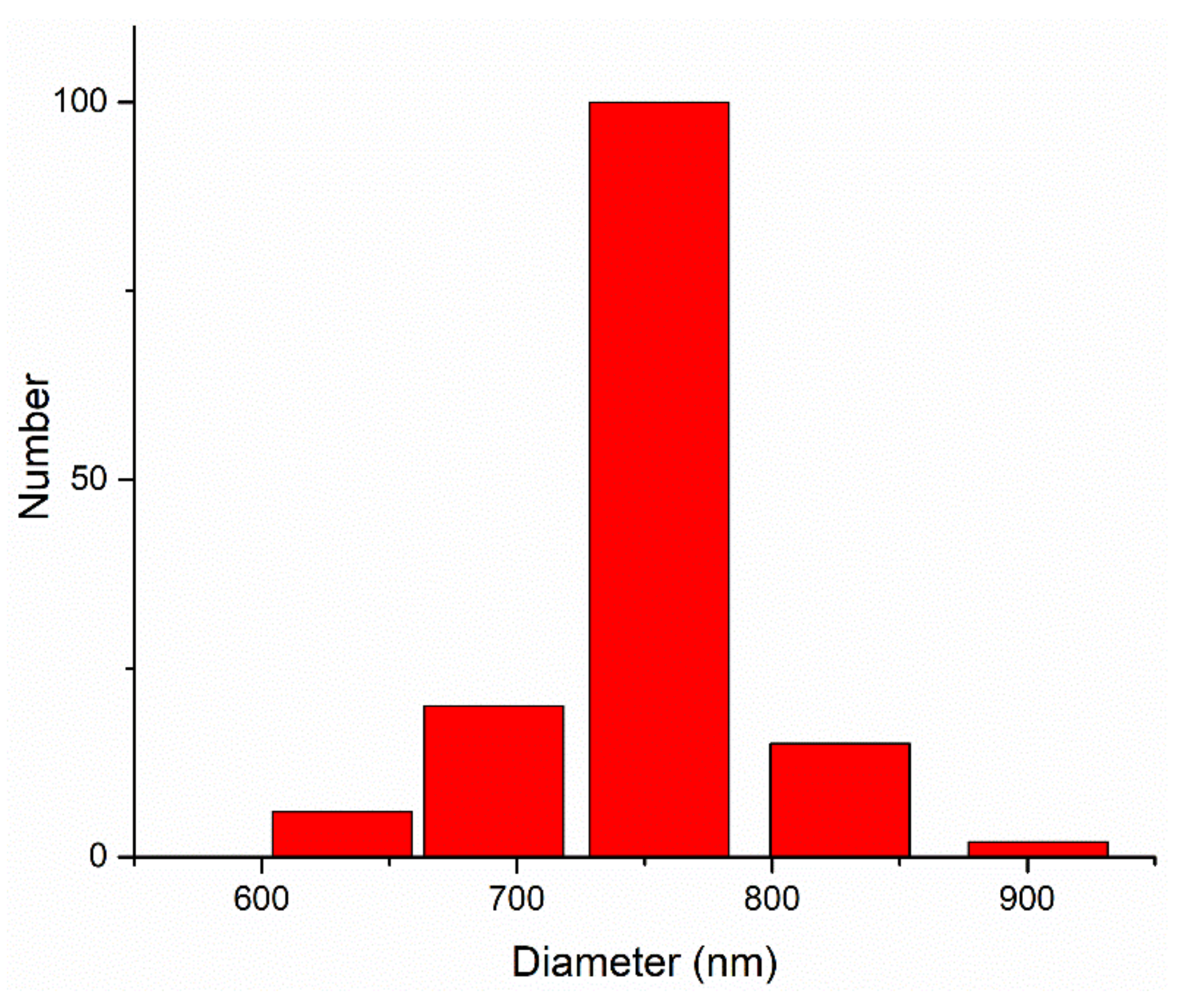
| d (nm) | G (d) | C (d) | d (nm) | G (d) | C (d) | d (nm) | G (d) | C (d) |
|---|---|---|---|---|---|---|---|---|
| 441.0 | 0 | 0 | 1183.7 | 0 | 100 | 3177.1 | 0 | 100 |
| 482.4 | 0 | 0 | 1294.8 | 0 | 100 | 3475.5 | 0 | 100 |
| 527.7 | 0 | 0 | 1416.4 | 0 | 100 | 3801.8 | 0 | 100 |
| 577.3 | 0 | 0 | 1549.5 | 0 | 100 | 4158.9 | 0 | 100 |
| 631.5 | 6 | 4 | 1695.0 | 0 | 100 | 4549.4 | 0 | 100 |
| 690.8 | 20 | 18 | 1854.1 | 0 | 100 | 4976.6 | 0 | 100 |
| 755.7 | 100 | 88 | 2028.3 | 0 | 100 | 5444.0 | 0 | 100 |
| 826.6 | 15 | 98 | 2218.7 | 0 | 100 | 5955.2 | 0 | 100 |
| 904.3 | 2 | 100 | 2427.1 | 0 | 100 | 6514.5 | 0 | 100 |
| 989.2 | 0 | 100 | 2655.0 | 0 | 100 | 7126.3 | 0 | 100 |
| 1082.1 | 0 | 100 | 2901.4 | 0 | 100 | 7795.5 | 0 | 100 |
| Sample Sintering Procedure | %Ti | %Al | %C | %Mn | %Zr | %Sn | %Others |
|---|---|---|---|---|---|---|---|
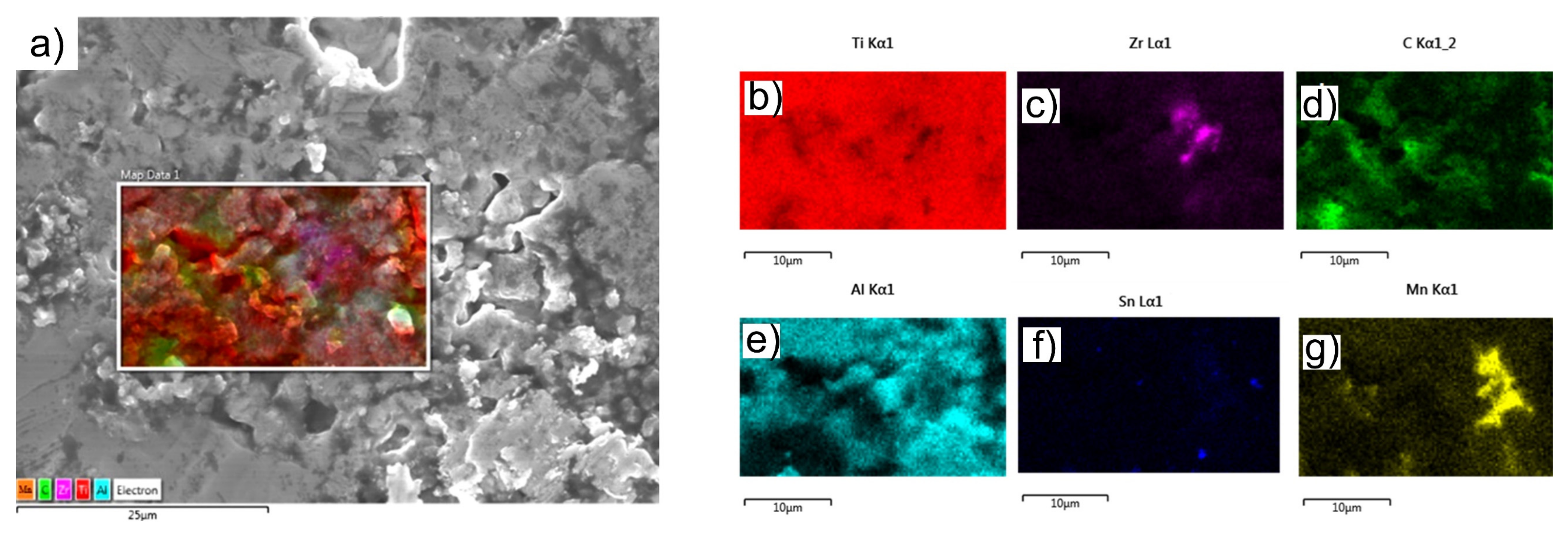
| TSS | 87.1 | 6.5 | 2.4 | 3.0 | 0.7 | - | 0.3 |
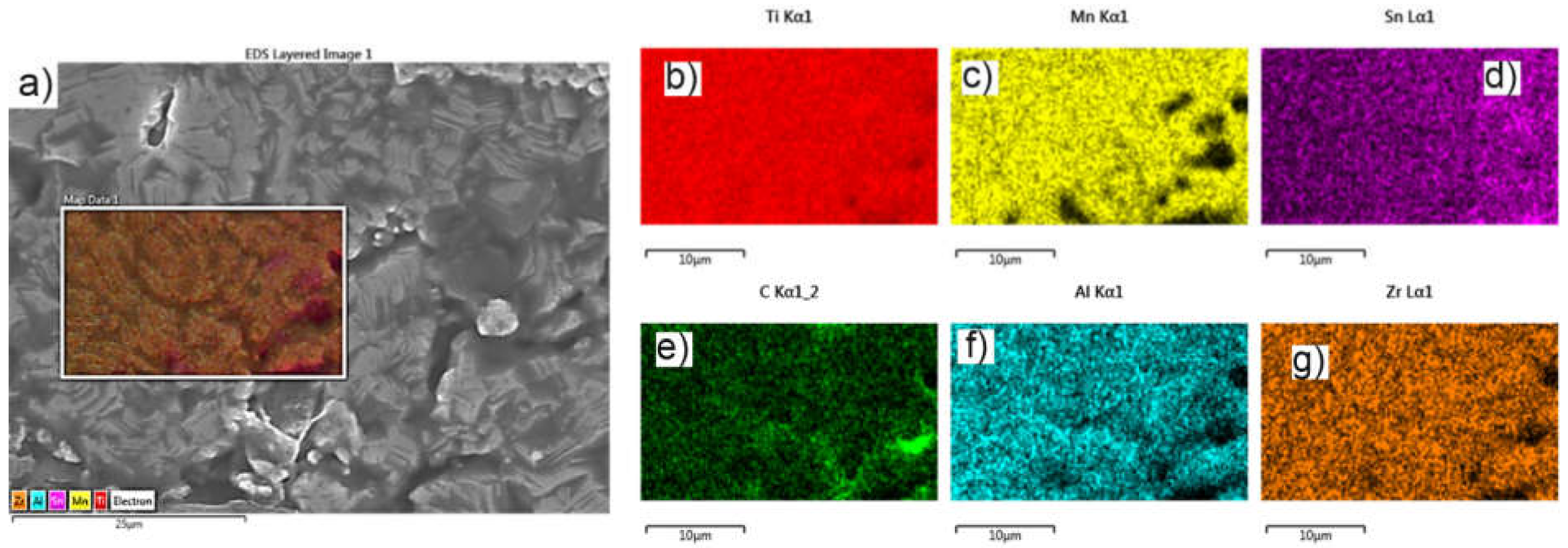
| MSS | 86.1 | 6.1 | 2.5 | 4.0 | 0.8 | - | 0.5 |
| Sample Sintering Procedure | Friction Coefficient | ||
|---|---|---|---|
| Min | Max | Average Value | |
| TSS | 0.094 | 0.578 | 0.545 |
| MSS | 0.089 | 0.604 | 0.567 |
| Sample Sintering Procedure | Worn Track Section (µm2) | Worn Cap Diameter (µm) | Sample Wear Rate (mm3·N−1·m−1)·10−5 | Partner Wear Rate (mm3·N−1·m−1)·10−5 |
|---|---|---|---|---|
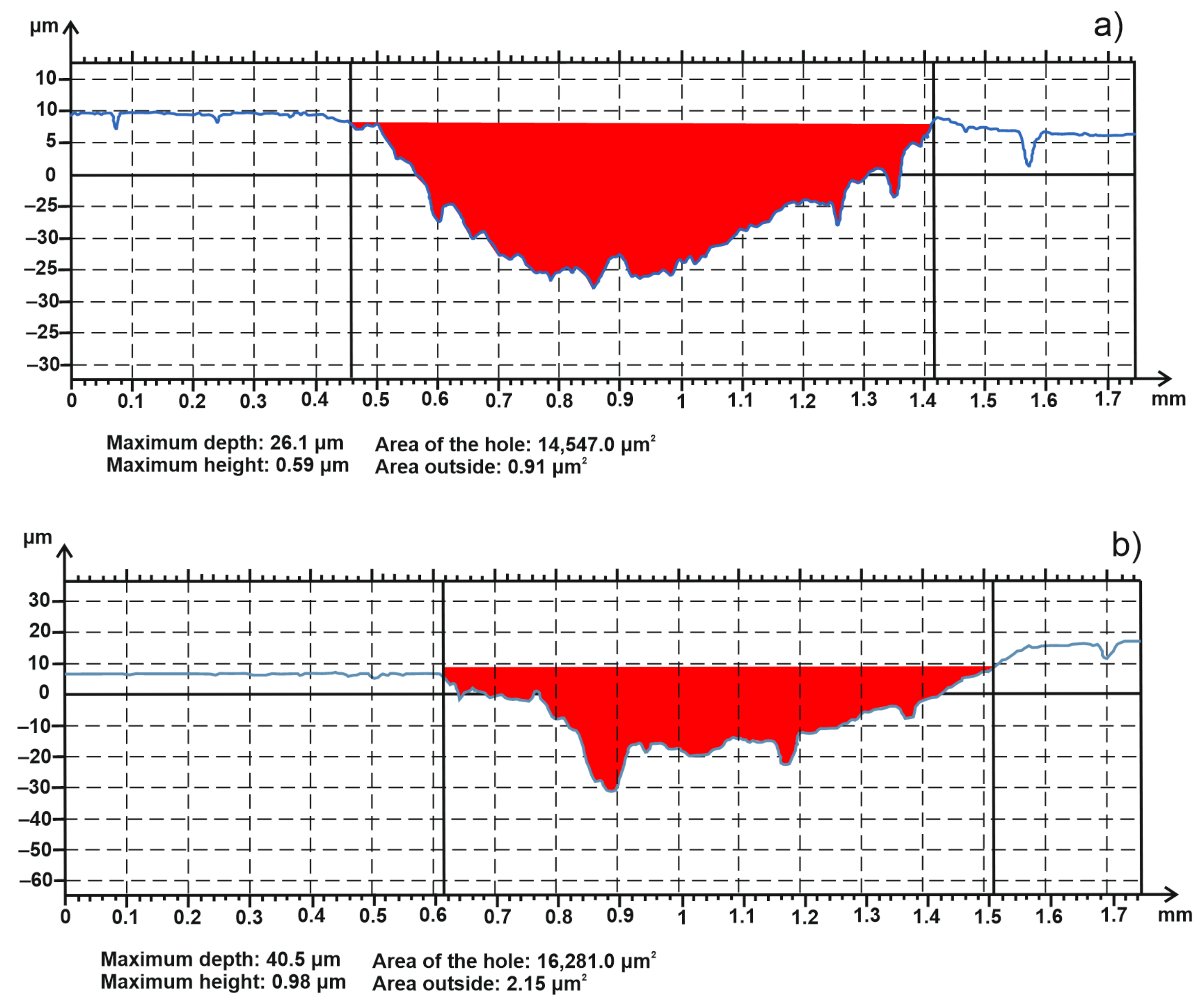
| TSS | 14547 | 589.5 | 182 | 4.129 |
| MSS | 16281 | 588.2 | 202.7 | 4.093 |
Publisher’s Note: MDPI stays neutral with regard to jurisdictional claims in published maps and institutional affiliations. |
© 2022 by the authors. Licensee MDPI, Basel, Switzerland. This article is an open access article distributed under the terms and conditions of the Creative Commons Attribution (CC BY) license (https://creativecommons.org/licenses/by/4.0/).
Share and Cite
Pascu, C.I.; Nicolicescu, C.; Cioateră, N.; Gheorghe, Ș.; Geonea, I.; Didu, A. Characterization of Titanium Alloy Obtained by Powder Metallurgy. Materials 2022, 15, 2057. https://doi.org/10.3390/ma15062057
Pascu CI, Nicolicescu C, Cioateră N, Gheorghe Ș, Geonea I, Didu A. Characterization of Titanium Alloy Obtained by Powder Metallurgy. Materials. 2022; 15(6):2057. https://doi.org/10.3390/ma15062057
Chicago/Turabian StylePascu, Cristina Ileana, Claudiu Nicolicescu, Nicoleta Cioateră, Ștefan Gheorghe, Ionuț Geonea, and Anca Didu. 2022. "Characterization of Titanium Alloy Obtained by Powder Metallurgy" Materials 15, no. 6: 2057. https://doi.org/10.3390/ma15062057
APA StylePascu, C. I., Nicolicescu, C., Cioateră, N., Gheorghe, Ș., Geonea, I., & Didu, A. (2022). Characterization of Titanium Alloy Obtained by Powder Metallurgy. Materials, 15(6), 2057. https://doi.org/10.3390/ma15062057