
The Effect of Surface Substrate Treatments on the Bonding Strength of Aluminium Inserts with Glass-Reinforced Poly(phenylene) Sulphide


Abstract
:1. Introduction
2. Materials and Methods
2.1. Surface Pre-Treatment of Al Inserts
- (a)
- Chemical 1: Bonding parts of Al inserts were dipped into etching solution (27.5 mL of H2SO4 (96%) + 7.5 mg of Na2Cr2O7 + 65 mL H₂O). The solution was heated to 65 ℃ for 1–15 min before dipping the inserts. Subsequently, the treated inserts were rinsed with distilled water and dried at the same temperature for 10 min in an oven.
- (b)
- Chemical 2: Bonding parts of Al inserts were treated in the same way as with chemical 1, but NaCl was used instead of Na2Cr2O7.
- (c)
- Plasma treatment: For surface modification of the Al inserts, a Plasma Beam Standard/PC (Diener Electronics, Ebhausen, Germany) was used at ambient temperature and atmospheric pressure. This is a device for cleaning and activating surfaces that has two nozzles with a maximum surface distance of 12 mm. One of the nozzles is presented in Figure 1 [15]. Completely clean and oxide-free surfaces can be obtained, as they are chemically struck by oxygen or air.
- (d)
- The surface energy was measured with contact angles at different distances and different times. The distance (8 mm) and time (20 s) were optimized to obtain the maximum effect from the plasma beam. The distance of 8 mm between the nozzle and the surface of the treated inserts was fixed. The gas used for the plasma treatment was introduced to the Al inserts. The discharge gas (compressed air) was generated using a frequency of 20 kHz and plasma power of 300 W AC, the gas flow rate was 11.2 L/min, and the cooling gas was maintained at 23.7 L/min. Unleaded air was used as a cooling gas.
- (e)
- Sandblasting: An in-depth abrasion treatment was carried out for the substratum using an SBC420 instrument (Reno-Tech s.r.o, Kaznejov, Czech Republic). As an abrasive material, slag (with the composition SiO2 30%, Al2O3 40%, CaO 30%) and 120 µm grains were used. The process was performed at a pressure of about 110 kPa and a distance of 8–10 cm from the nozzle for 50 s, at a right angle to the substrate surface [16].
- (f)
- S + P combination: Sandblasting was undertaken in the same way as described above; this was followed by plasma treatment. Inserts were cleaned with acetone after sandblasting and dried before plasma treatment.
2.2. Al Insert Surface Morphology Description
- (1)
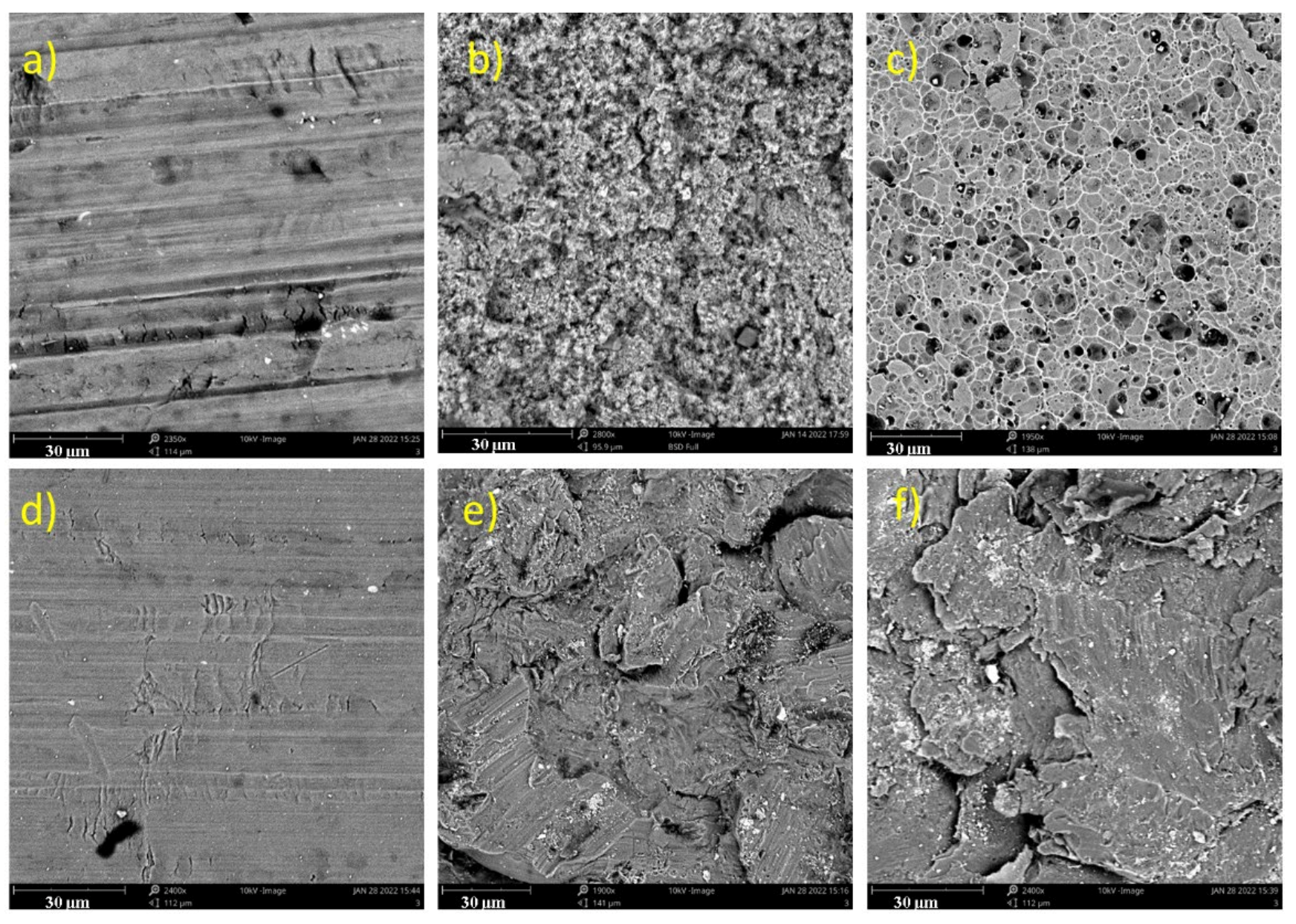
- To describe the surface morphologies of the differently treated Al inserts a high-resolution scanning electron microscope (SEM) Phenom Pro X (Waltham, MA, USA) with an electron accelerating voltage of 5 kV was used.
- (2)
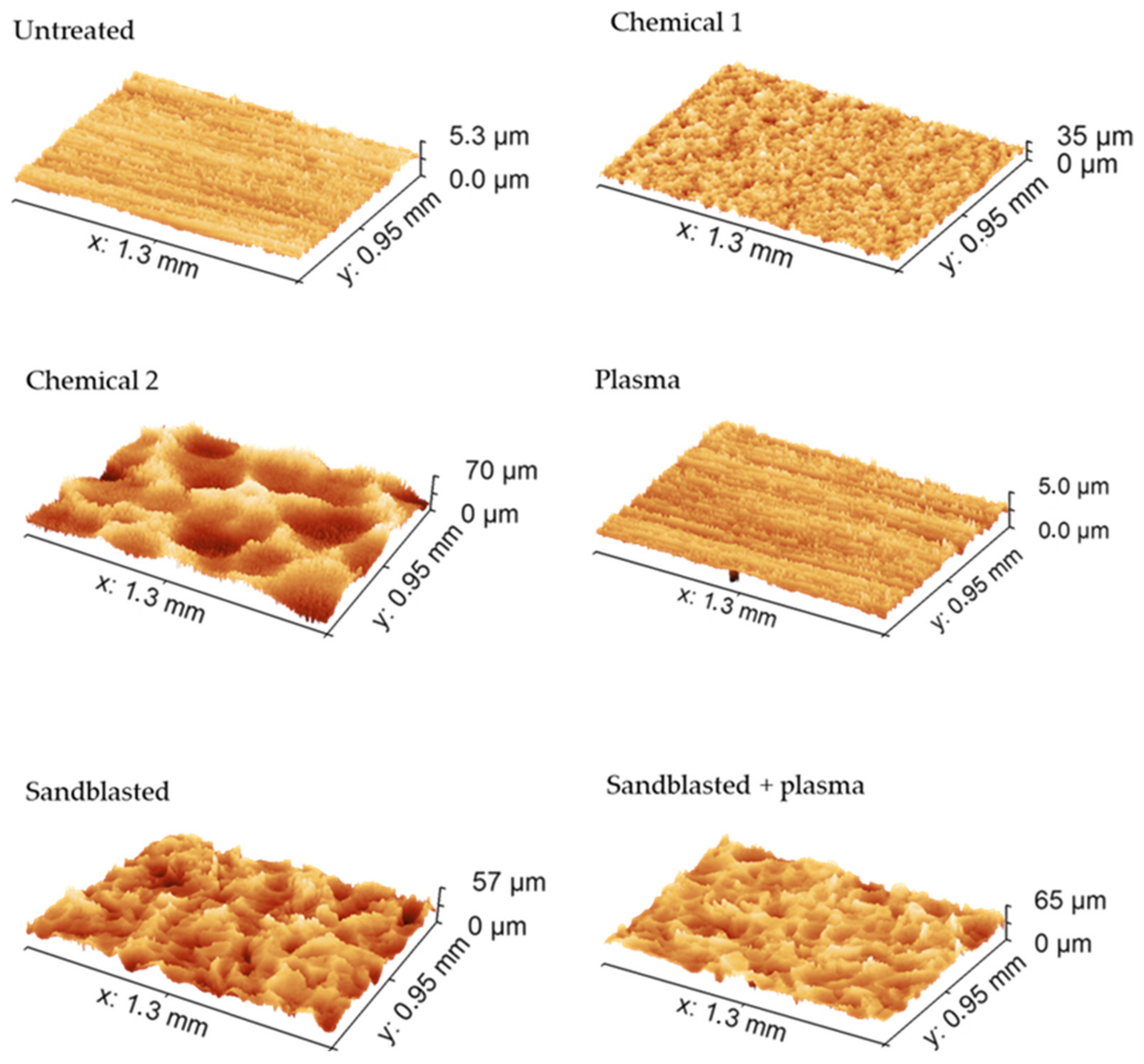
- The surface roughness (Ra) of the Al inserts was evaluated with a TR100 surface roughness tester (Time Group Inc, Beijing City, China), and the surface roughness (Sa) was characterized with a 3D optical microscope from 3D images. A Contour GT-K (Bruker, Tucson, AZ, USA) based on white light interferometry was used with a 20× objective lens. The resulting 3D topography maps were processed using Gwyddion 2.55 software (Brno, Czech Republic).
- (3)
- The contact angles of the tested surfaces were analysed using a Surface Energy Evaluation System (SEE System; Advex Instruments, Brno, Czech Republic). The apparatus was used to visualize the drop’s tangent (right and left) and the three-phase points. Each representative contact angle was calculated by averaging at least ten separate readings for every sample (the results are presented in Table 1). Deionized water was used as a testing liquid, and digital images of a 2 µL water droplet on the surface were captured with a charge-coupled device camera system.
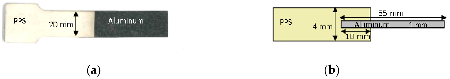
2.3. Preparation of Bi-Component Specimens via Injection Over-Moulding
3. Results and Discussions
3.1. Surface Morphologies of Al Inserts
3.1.1. SEM
3.1.2. Roughness
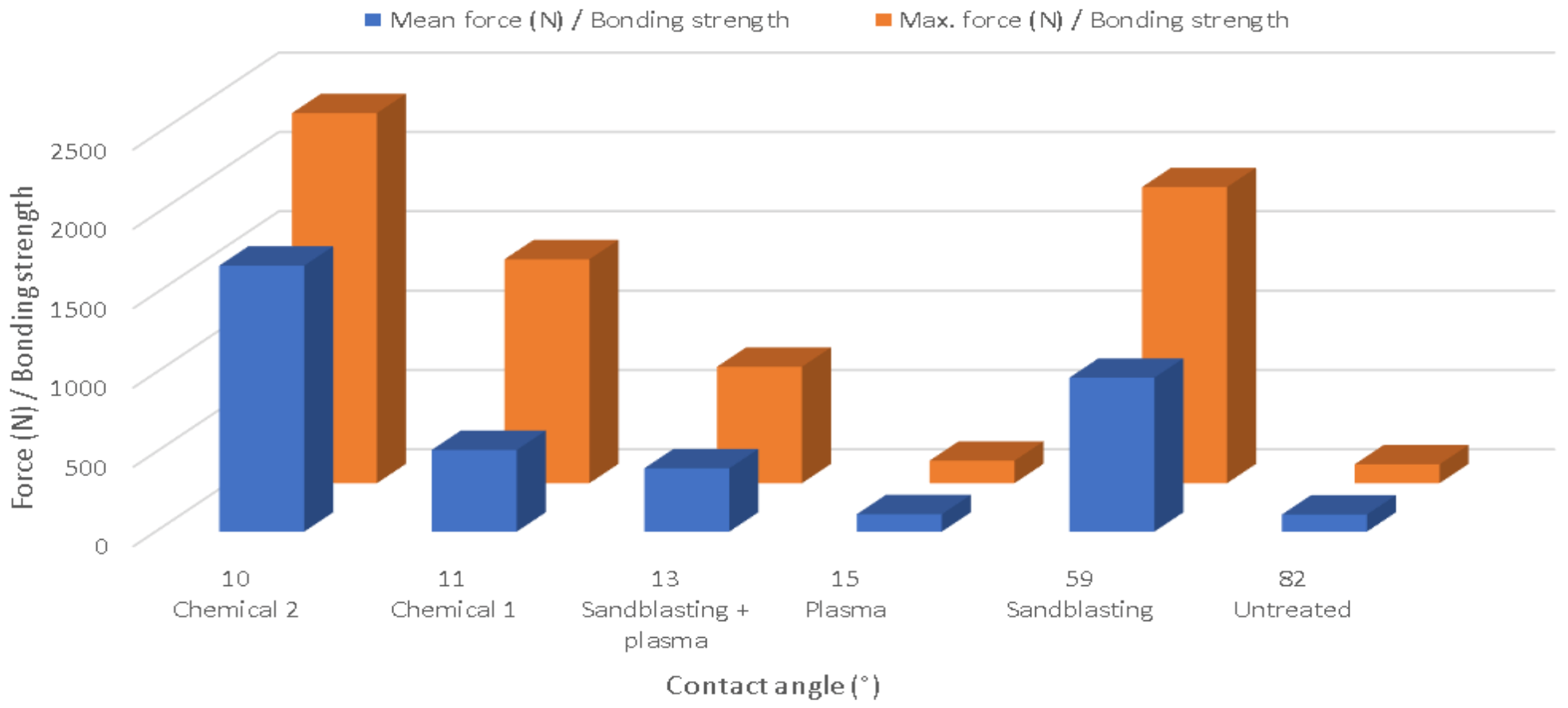
3.1.3. Contact Angle
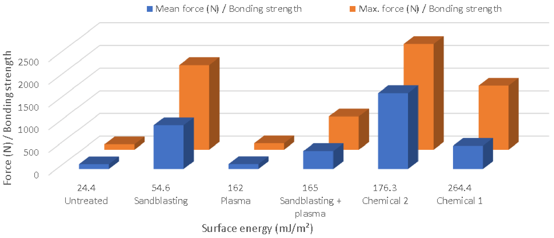
3.2. Bonding Strength of the Bi-Component Specimen
4. Conclusions
Author Contributions
Funding
Institutional Review Board Statement
Informed Consent Statement
Data Availability Statement
Acknowledgments
Conflicts of Interest
References
- Li, X.; Liu, F.; Gong, N.; Yang, C.; Wang, B. Surface Topography Induced High Injection Joining Strength of Polymer-Metal Composite and Fracture Mechanism. Compos. Struct. 2018, 184, 545–553. [Google Scholar] [CrossRef]
- Martinsen, K.; Hu, S.J.; Carlson, B.E. Joining of Dissimilar Materials. CIRP Ann. Manuf. Technol. 2015, 64, 679–699. [Google Scholar] [CrossRef] [Green Version]
- Mandolfino, C.; Lertora, E.; Gambaro, C. Effect of Surface Pretreatment on the Performance of Adhesive-Bonded Joints. In Key Engineering Materials; Trans Tech Publications Ltd.: Bach, Switzerland, 2013; Volume 554–557, pp. 996–1006. [Google Scholar]
- Xu, Z.; Li, N. Effects of Surface Microstructure and Molding Parameters on Injection Bonding Strength of Polyphenylenesulphide-Aluminum Alloy. Mater. Express 2020, 10, 640–647. [Google Scholar] [CrossRef]
- Iqbal, H.M.S.; Bhowmik, S.; Poulis, J.A.; Benedictus, R. Effect of Plasma Treatment and Electron Beam Radiations on the Strength of Nanofilled Adhesive-Bonded Joints. Polym. Eng. Sci. 2010, 50, 1505–1511. [Google Scholar] [CrossRef]
- Lucchetta, G.; Marinello, F.; Bariani, P.F. Aluminum Sheet Surface Roughness Correlation with Adhesion in Polymer Metal Hybrid Overmolding. CIRP Ann.—Manuf. Technol. 2011, 60, 559–562. [Google Scholar] [CrossRef]
- Grujicic, M.; Sellappan, V.; Omar, M.A.; Seyr, N.; Obieglo, A.; Erdmann, M.; Holzleitner, J. An Overview of the Polymer-to-Metal Direct-Adhesion Hybrid Technologies for Load-Bearing Automotive Components. J. Mater. Process. Technol. 2008, 197, 363–373. [Google Scholar] [CrossRef]
- Ochoa-Putman, C.; Vaidya, U.K. Mechanisms of Interfacial Adhesion in Metal-Polymer Composites—Effect of Chemical Treatment. Compos. Part A Appl. Sci. Manuf. 2011, 42, 906–915. [Google Scholar] [CrossRef]
- Shahid, M.; Hashim, S.A. Effect of Surface Roughness on the Strength of Cleavage Joints; Elsevier: Amsterdam, The Netherlands, 2002; Volume 22. [Google Scholar]
- Iqbal, H.M.S.; Bhowmik, S.; Benedictus, R. Surface Modification of High Performance Polymers by Atmospheric Pressure Plasma and Failure Mechanism of Adhesive Bonded Joints. Int. J. Adhes. Adhes. 2010, 30, 418–424. [Google Scholar] [CrossRef]
- Kadlečková, M.; Minařík, A.; Smolka, P.; Mráček, A.; Wrzecionko, E.; Novák, L.; Musilová, L.; Gajdošík, R. Preparation of Textured Surfaces on Aluminum-Alloy Substrates. Materials 2018, 12, 109. [Google Scholar] [CrossRef] [PubMed] [Green Version]
- Heckert, A.; Zaeh, M.F. Laser Surface Pre-Treatment of Aluminium for Hybrid Joints with Glass Fibre Reinforced Thermoplastics. Phys. Procedia 2014, 56, 1171–1181. [Google Scholar] [CrossRef] [Green Version]
- Moritz, J.; Götze, P.; Schiefer, T.; Stepien, L.; Klotzbach, A.; Standfuß, J.; López, E.; Brückner, F.; Leyens, C. Additive Manufacturing of Titanium with Different Surface Structures for Adhesive Bonding and Thermal Direct Joining with Fiber-Reinforced Polyether-Ether-Ketone (PEEK) for Lightweight Design Applications. Metals 2021, 11, 265. [Google Scholar] [CrossRef]
- Gardiner, G. Overmolding Expands PEEK’s Range in Composites. CompositesWorld. 1 July 2015. Available online: https://www.compositesworld.com/articles/overmolding-expands-peeks-range-in-composites (accessed on 5 January 2022).
- Handbook of Plasma Surface Technnology—Plasma Technology; Diener Electronic GmbH Co. KG: Ebhausen, Germany, 2020.
- Miturska-Barańska, I.; Rudawska, A.; Doluk, E. The Influence of Sandblasting Process Parameters of Aerospace Aluminium Alloy Sheets on Adhesive Joints Strength. Materials 2021, 14, 6626. [Google Scholar] [CrossRef] [PubMed]
- Wurzbacher, S.; Gach, S.; Reisgen, U.; Hopmann, C. Joining of Plastic-Metal Hybrid Components by Overmoulding of Specially Designed Form-Closure Elements (Fügen von Kunststoff-Metall-Hybridbauteilen Durch Das Hinterspritzen Gezielt Aufgebauter Formschlusselemente). Mater. Werkst. 2021, 52, 367–378. [Google Scholar] [CrossRef]
- Leahy, W.; Barron, V.; Buggy, M.; Young, T.; Mas, A.; Schue, F.; McCabe, T.; Bridge, M. Plasma Surface Treatment of Aerospace Materials for Enhanced Adhesive Bonding. J. Adhes. 2001, 77, 215–249. [Google Scholar] [CrossRef]


| Types of Aluminium Inserts/PPS Surface | Contact Angle (°) | Surface Energy (mJ/m2) | Deviation Surface Energy |
|---|---|---|---|
| Untreated | 82 | 24.4 | ± 1.5 |
| Chemical 1 | 11 | 264.4 | ± 12.4 |
| Chemical 2 | 10 | 176.3 | ± 6.2 |
| Plasma | 15 | 162.0 | ± 5.5 |
| Sandblasting | 59 | 54.6 | ± 3.1 |
| Sandblasting + plasma | 13 | 165.0 | ± 4.8 |
| PPS | 99 | 32.3 | ± 1.2 |
| Injection Speed (mm/s) | 130 |
|---|---|
| Injection pressure (MPa) | 60 |
| Cooling temperature under the hopper (℃) | 40–50 |
| Zones 1, 2, 3, and 4 temperatures (℃) | 290, 310, 330, 330 |
| Nozzle temperature (℃) | 310 |
| Holding pressure (MPa) | 45 |
| Holding time (s) | 7 |
| Cooling time (s) | 15 |
| Mould temperature (℃) | 120 |
| Untreated | Chemical 1 | Chemical 2 | Plasma | Sandblasting | Sandblasting + Plasma | |
|---|---|---|---|---|---|---|
| Roughness (Sa; µm) before shear test | 0.5 ± 0.1 | 3.1 ± 0.6 | 7.9 ± 1.4 | 0.90 ± 0.1 | 6.5 ± 0.8 | 6.7 ± 0.5 |
| Roughness (Sa; µm) after shear test | 0.4 ± 0.2 | 3.1 ± 0.5 | 8.0 ± 1.2 | 0.5 ± 0.1 | 6.5 ± 0.7 | 6.2 ± 0.2 |
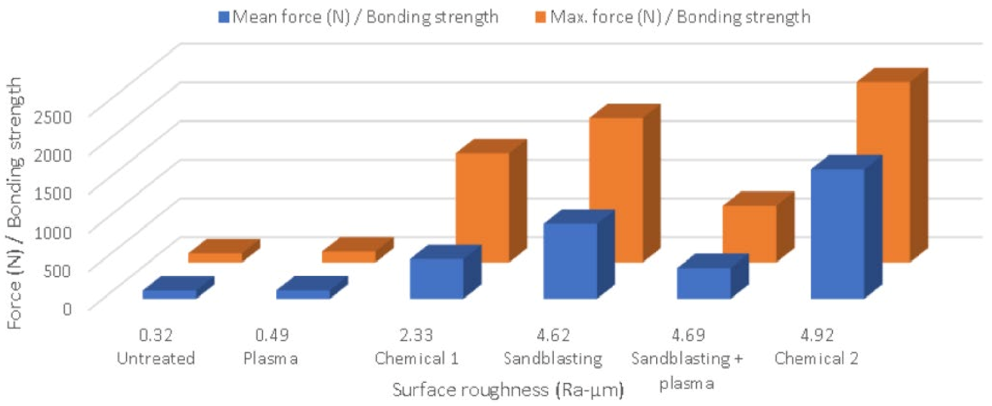
| Types of Aluminium Inserts | Surface Roughness (Ra; µm) | Deviation of Surface Roughness (Ra; µm) | Bonding Strength/Max. Force (N) | Bonding Strength/Mean Force (N) |
|---|---|---|---|---|
| Untreated | 0.32 | ± 0.06 | 119 | 108 |
| Chemical 1 | 2.33 | ± 0.83 | 1411 | 515 |
| Chemical 2 | 4.92 | ± 1.86 | 2332 | 1676 |
| Plasma | 0.49 | ± 0.09 | 142 | 110 |
| Sandblasting | 4.62 | ± 1.49 | 1866 | 970 |
| Sandblasting + plasma | 4.69 | ± 1.27 | 734 | 399 |
Publisher’s Note: MDPI stays neutral with regard to jurisdictional claims in published maps and institutional affiliations. |
© 2022 by the authors. Licensee MDPI, Basel, Switzerland. This article is an open access article distributed under the terms and conditions of the Creative Commons Attribution (CC BY) license (https://creativecommons.org/licenses/by/4.0/).
Share and Cite
Matta, A.; Sedlacek, T.; Kadleckova, M.; Lengalova, A. The Effect of Surface Substrate Treatments on the Bonding Strength of Aluminium Inserts with Glass-Reinforced Poly(phenylene) Sulphide. Materials 2022, 15, 1929. https://doi.org/10.3390/ma15051929
Matta A, Sedlacek T, Kadleckova M, Lengalova A. The Effect of Surface Substrate Treatments on the Bonding Strength of Aluminium Inserts with Glass-Reinforced Poly(phenylene) Sulphide. Materials. 2022; 15(5):1929. https://doi.org/10.3390/ma15051929
Chicago/Turabian StyleMatta, Ashish, Tomas Sedlacek, Marketa Kadleckova, and Anezka Lengalova. 2022. "The Effect of Surface Substrate Treatments on the Bonding Strength of Aluminium Inserts with Glass-Reinforced Poly(phenylene) Sulphide" Materials 15, no. 5: 1929. https://doi.org/10.3390/ma15051929
APA StyleMatta, A., Sedlacek, T., Kadleckova, M., & Lengalova, A. (2022). The Effect of Surface Substrate Treatments on the Bonding Strength of Aluminium Inserts with Glass-Reinforced Poly(phenylene) Sulphide. Materials, 15(5), 1929. https://doi.org/10.3390/ma15051929