
The Stability of Spiral-Grooved Air Journal Bearings in Ultrahigh Speeds


Abstract
:1. Introduction
2. Materials and Methods
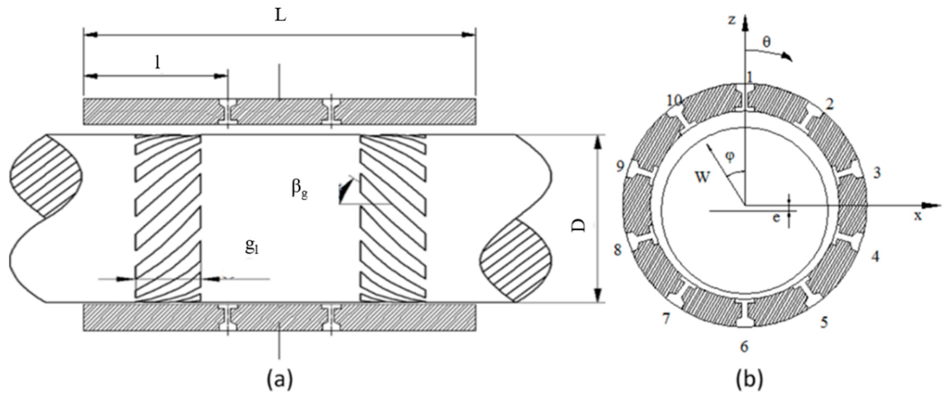
2.1. Calculation of the Dynamic Characteristics of Spiral-Grooved Hybrid Air Journal Bearings
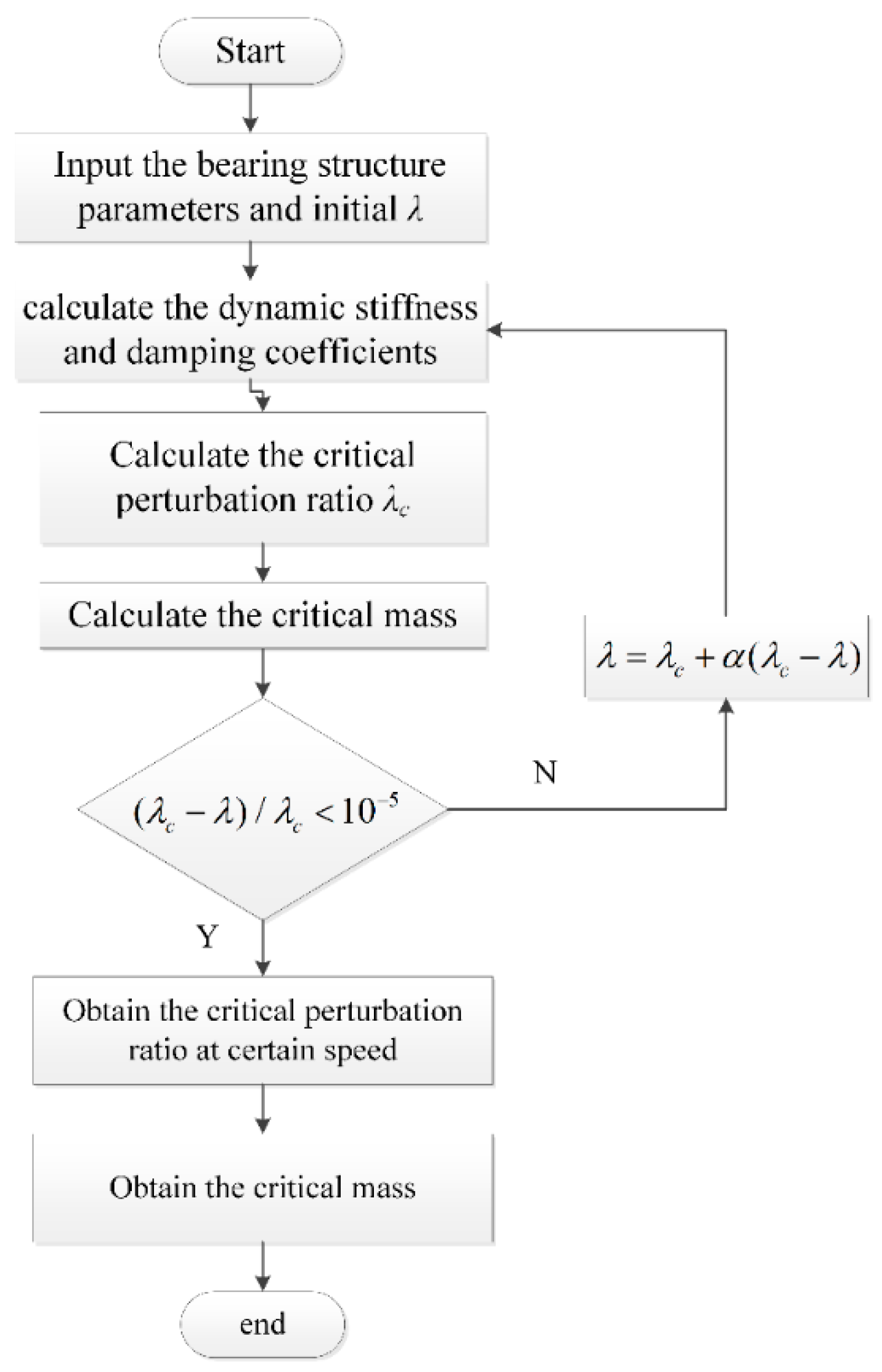
2.2. Stability Characteristics of Spiral-Grooved Hybrid Air Journal Bearings
3. Results
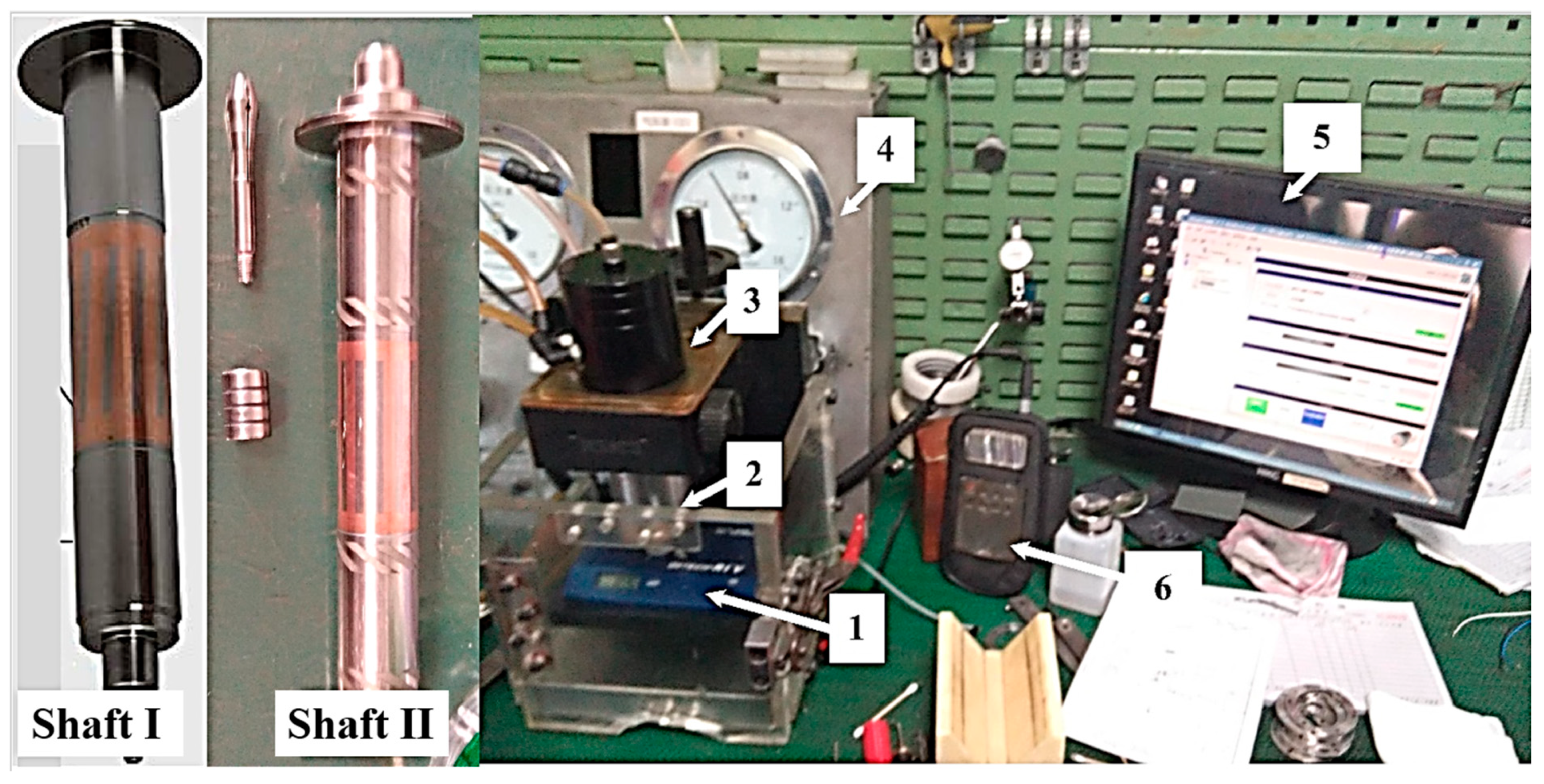
4. Experiments
5. Conclusions
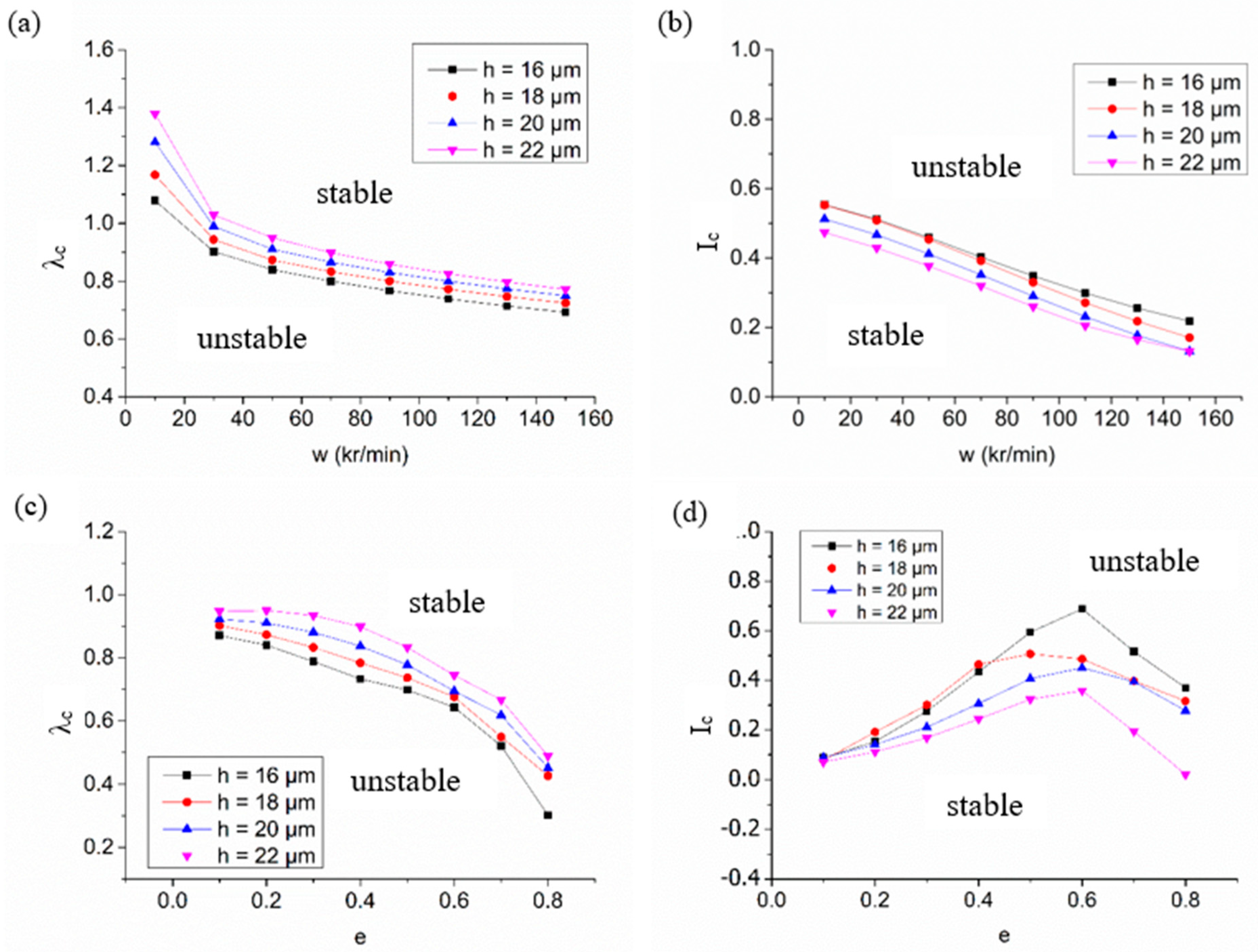
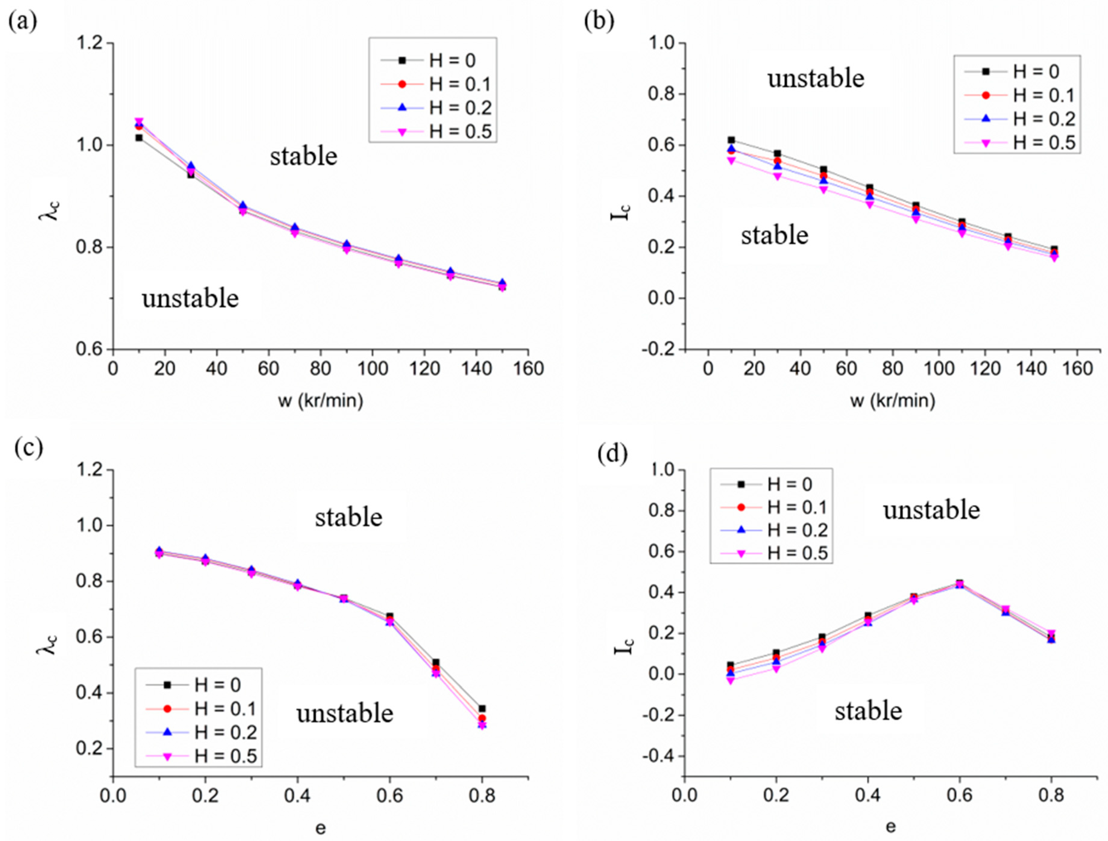
- With increased rotation speed, the critical perturbation ratio increases, while the critical mass decreases. It can be concluded that the stability margin is enhanced by increasing rotation speed.
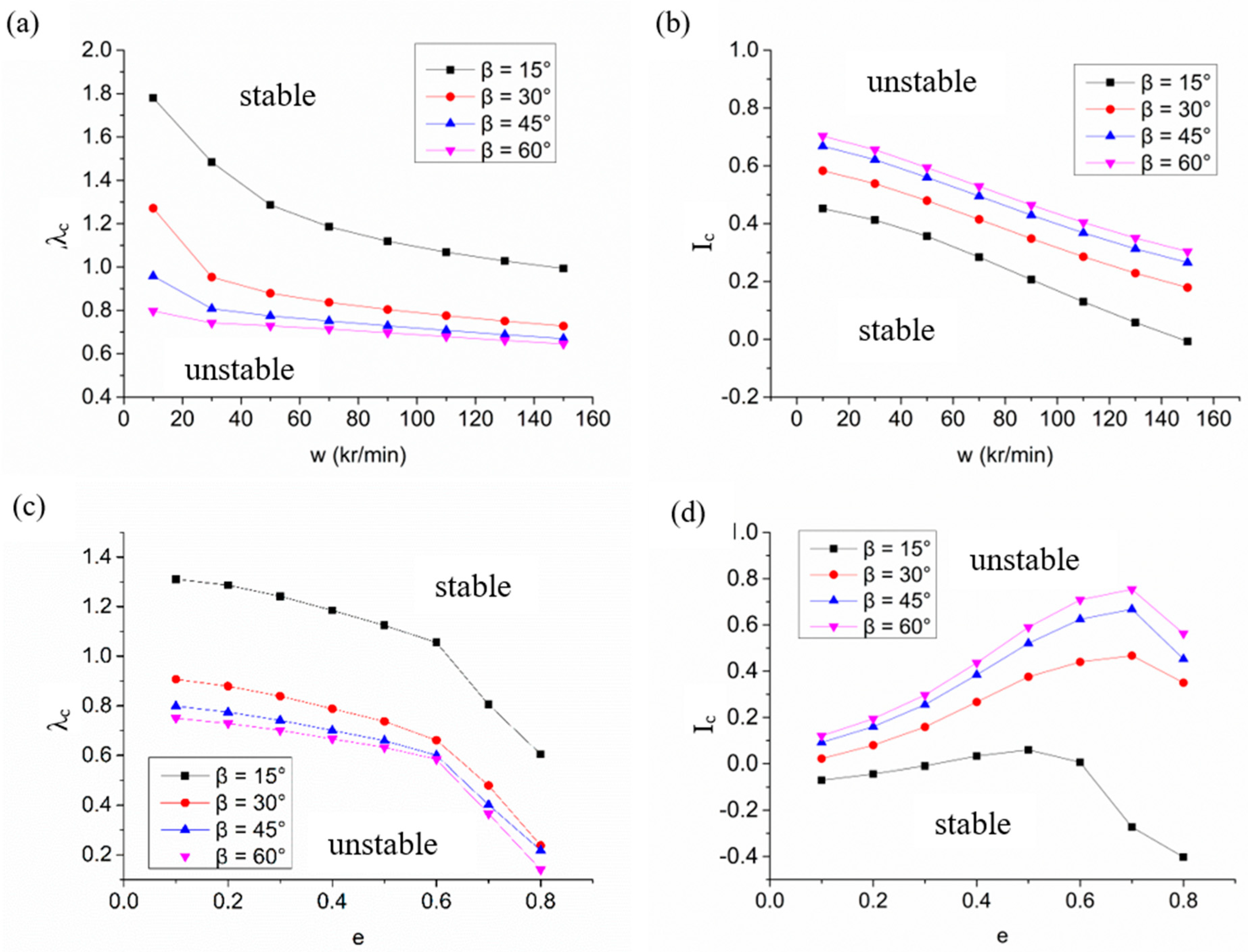
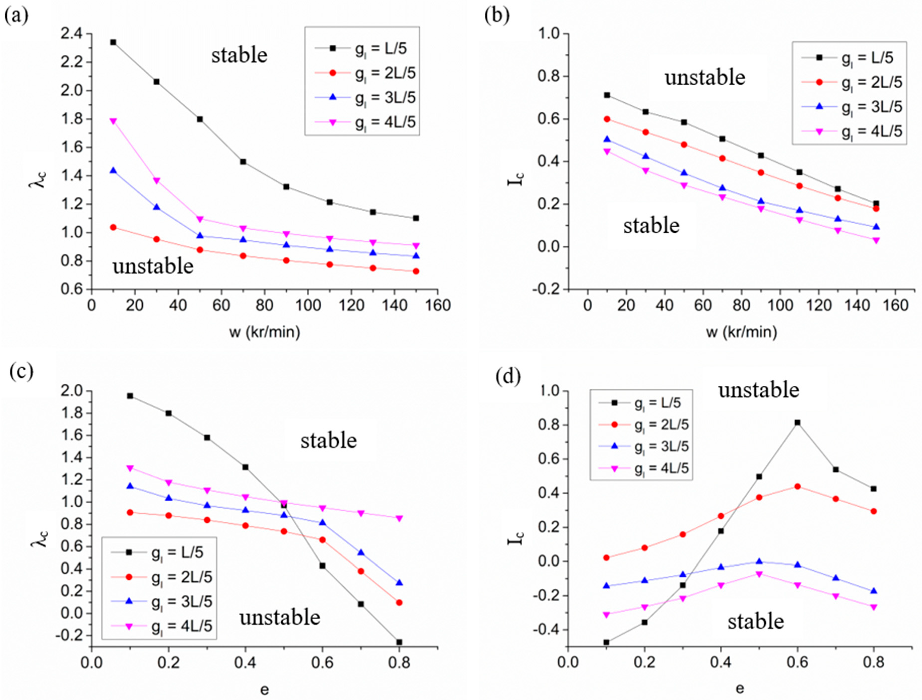
- The stability margin of a spiral-grooved hybrid air spindle can be promoted by enlarging the groove angle. However, when the groove angle is larger than 45°, the enhancement is not obvious. The influence of groove depth on stability characteristics is limited because groove depth mainly affected the cross-coupled stiffness. The hybrid air spindle with spiral grooves that are too large or too short will obtain a lower critical perturbation ratio, which leads to a decline in stability.
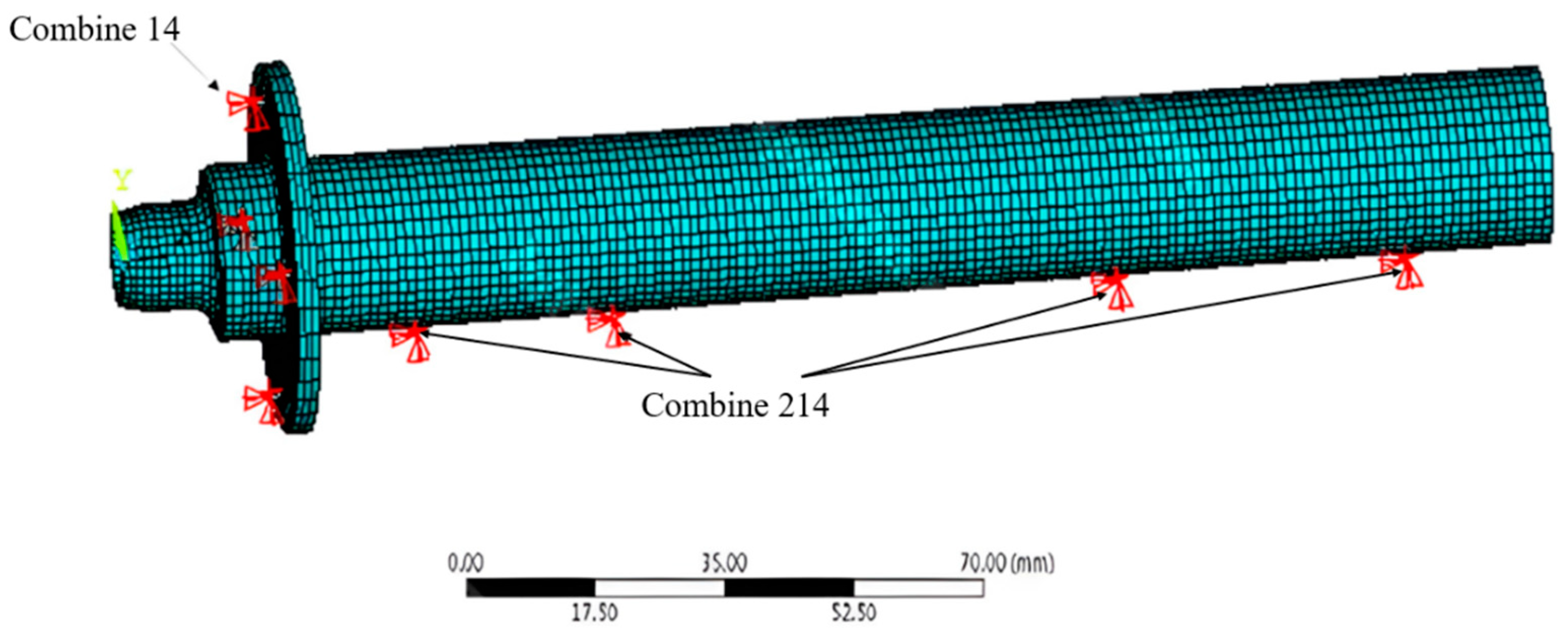
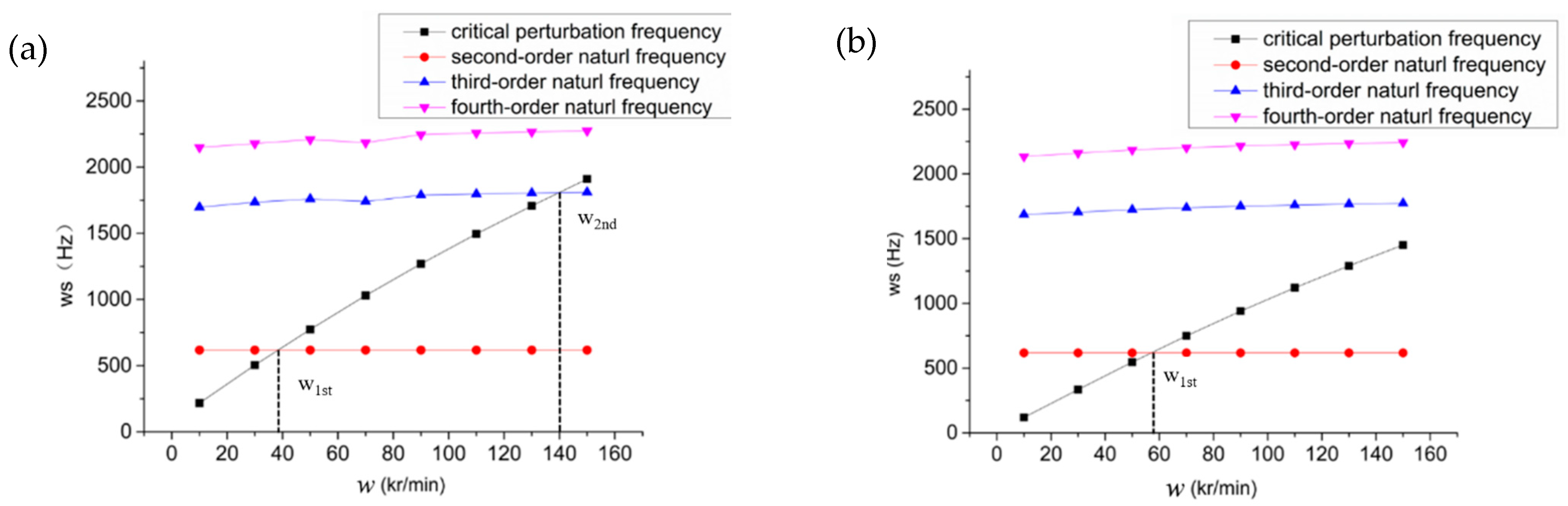
- The second- to fourth-order natural frequencies of a hybrid air spindle are the main causes of spindle vibration, which are responsive to yaw around the Y axis, to the front end of the shaft around the X axis and to the rear end of the shaft around the X axis, respectively. The critical speed of a hybrid air spindle with spiral grooves is larger than that of a spindle without spiral grooves. The enhancement of the critical speed is due to the improvement of the dynamic stiffness and the damping coefficients.
- The designed spiral-grooved hybrid air spindle and an ordinary hybrid spindle was tested on the vibration in both axial and radial directions. The experiments showed results consistent with the calculated critical speed and verified the effect of groove structure on promoting the stability of a hybrid air spindle.
Author Contributions
Funding
Institutional Review Board Statement
Informed Consent Statement
Data Availability Statement
Acknowledgments
Conflicts of Interest
Nomenclature
| Cd | Discharge coefficient |
| d | Orifice diameter (mm) |
| e | Eccentricity ratio |
| f | Approximate solution |
| Pressure square function | |
| , | Dimensionless square atmosphere and downstream pressure |
| Dimensionless air film thickness | |
| H | Dimensionless groove depth (H = gd/c) |
| Kxx, Kyy, Kz | Translational stiffness |
| Kθx, Kθy | Angular stiffness |
| L | Bearing length (mm) |
| Actual rth mass flow rate (kg/s) | |
| Theoretical mass flow rate (kg/s) | |
| Dimensionless air film pressure | |
| Atmosphere pressure | |
| Supply pressure | |
| P0 | Dimensionless air film pressure in steady state |
| Velocity components in the x and z directions (m/s) | |
| , | Moment in x- and y- direction (N) |
| , | Dimensionless coordinates |
| Perturbation frequency ratio | |
| η | Air dynamic viscosity |
| Delta function | |
| ρ | Air density (kg/m3) |
| Air density at atmosphere pressure (kg/m3) | |
| Λ | Compressibility number |
| , | Dimensionless bearing numbers in the x- and z- direction |
| κ | Specific heat ratio of air |
References
- Cheng, K.; Huo, D.H. Mirco Cutting: Fundamentals and Applications; John Wiley & Sons, Ltd.: West Sussex, UK, 2013. [Google Scholar]
- Abele, E.; Altintas, Y.; Brecher, C. Machine tool spindle units. CIRP Ann.-Manuf. Technol. 2010, 59, 781–802. [Google Scholar] [CrossRef]
- Su, J.C.T.; Lie, K.N. Rotation effects on hybrid air journal bearings. Tribol. Int. 2003, 36, 717–726. [Google Scholar] [CrossRef]
- Su, J.C.T.; Lie, K.N. Rotor dynamic instability analysis on hybrid air journal bearings. Tribol. Int. 2006, 39, 238–248. [Google Scholar] [CrossRef]
- Gao, Q.; Chen, W.Q.; Lu, L.H.; Huo, D.; Cheng, K. Aerostatic bearings design and analysis with the application to precision engineering: State-of-the-art and future perspectives. Tribol. Int. 2019, 135, 1–17. [Google Scholar] [CrossRef]
- Liu, Q.; Liao, Z.; Cheng, J. Mechanism of chip formation and surface-defects in orthogonal cutting of soft-brittle potassium dihydrogen phosphate crystals. Mater. Des. 2021, 198, 109327. [Google Scholar] [CrossRef]
- Liu, Q.; Liao, Z.; Axinte, D. Temperature effect on the material removal mechanism of soft-brittle crystals at nano/micron scale. Int. J. Mach. Tools Manuf. 2020, 159, 103620. [Google Scholar] [CrossRef]
- Fourka, M.; Tian, Y.; Bonis, M. Prediction of the stability of air thrust bearings by numerical, analytical and experimental methods. Wear 1996, 198, 1–6. [Google Scholar] [CrossRef]
- Miyatake, M.; Yoshimoto, S.; Sato, J. Whirling instability of a rotor supported by aerostatic porous journal bearings with a surface-restricted layer. J. Eng. Tribol. 2006, 220, 95–103. [Google Scholar] [CrossRef]
- Chen, C.-H.; Tsai, T.-H.; Yang, D.-W.; Kang, Y.; Chen, J.H. The comparison in stability of rotor-aerostatic bearing system compensated by orifices and inherences. Tribol. Int. 2010, 43, 1360–1373. [Google Scholar] [CrossRef]
- Maamari, N.; Krebs, A.; Weikert, S.; Wild, H.; Wegener, K. Stability and dynamics of an orifice based aerostatic bearing with a compliant back plate. Tribol. Int. 2019, 138, 279–296. [Google Scholar] [CrossRef]
- Zheng, Y.Q.; Yang, G.W.; Cui, H.L.; Hou, Y. Pneumatic stability analysis of single-pad aerostatic thrust bearing with pocketed orifice. J. Eng. Tribol. 2020, 234, 1857–1866. [Google Scholar] [CrossRef]
- Vohr, J.H.; Chow, C.Y. Characteristics of Herringbone-Grooved, Gas-Lubricated Journal Bearings. J. Basic Eng. 1965, 87, 568–576. [Google Scholar] [CrossRef]
- Chen, M.F.; Lin, Y.T. Dynamic analysis of the X-shaped groove aerostatic bearings with disk-spring compensator. JSME Int. J. Ser. C Mech. Syst. Mach. Elem. Manuf. 2002, 45, 492–501. [Google Scholar] [CrossRef] [Green Version]
- Belforte, G.; Colombo, F.; Raparelli, T.; Trivella, A.; Viktorov, V. Comparison between grooved and plane aerostatic thrust bearings: Static performance. Meccanica 2011, 46, 547–555. [Google Scholar] [CrossRef] [Green Version]
- Yang, G.W.; Du, J.J.; Ge, W.P.; Liu, T.; Yang, X. Dynamic Characteristics of Spiral-Grooved Opposed-Hemisphere Gas Bearings. J. Tribol. 2017, 139, 11. [Google Scholar] [CrossRef]
- Stanev, P.T.; Wardle, F.; Corbett, J. Investigation of grooved hybrid air bearing performance. J. Multi-Body Dyn. 2004, 218, 95–106. [Google Scholar] [CrossRef]
- Jia, C.H.; Pang, H.J.E.; Ma, W.S.; Qui, M. Dynamic Stability Prediction of Spherical Spiral Groove Hybrid Gas Bearings Rotor System. J. Tribol. 2017, 139, 12. [Google Scholar] [CrossRef]
- Song, L.; Cheng, K.; Ding, H.; Chen, S.; Gao, Q. Analysis of static and dynamic characteristics of spiral-grooved gas journal bearings in high speed. J. Mech. Eng. Sci. 2019, 233, 6774–6792. [Google Scholar] [CrossRef]


| Bearing Geometric Parameters and Operating Parameters | Value |
|---|---|
| Bearing diameter (D) | 19.01 mm |
| Bearing length (L) | 34.813 mm |
| Radius clearance (c) | 21.5 μm |
| Orifice diameter (d) | 0.12 mm |
| Column number of feeding orifices | 2 |
| Number of orifice on each column | 10 |
| Axial distance between orifice and bearing end face (L1) | 12.7 mm |
| Groove depth (gd) | 10 μm |
| Groove angle (βg) | π/6 |
| Groove length (gl) | 12.7 mm |
| Groove width ratio (α = wg/(wr + wg)) | 0.5 |
| Supplied pressure(Ps) | 6 bar |
| Rotation Speed (r/min) | Second-Order fs (Hz) | Third-Order fs (Hz) | Fourth-Order fs (Hz) | Fifth-Order fs (Hz) | Sixth-Order fs (Hz) | Seventh-Order fs (Hz) |
|---|---|---|---|---|---|---|
| 10,000 | 617.67 | 1687 | 2134.1 | 3469.9 | 4285.1 | 4600 |
| 30,000 | 617.67 | 1704.3 | 2160.5 | 3484.3 | 4285.1 | 4610.7 |
| 50,000 | 617.67 | 1724 | 2185 | 3496.4 | 4285.1 | 4618.5 |
| 70,000 | 617.67 | 1739.3 | 2202.6 | 3504 | 4285.1 | 4623.3 |
| 90,000 | 617.67 | 1751.2 | 2216.3 | 3509.3 | 4285.1 | 4626.9 |
| 110,000 | 617.67 | 1759.9 | 2226.3 | 3513 | 4285.1 | 4629.5 |
| 130,000 | 617.67 | 1767.5 | 2235.3 | 3515.7 | 4285.1 | 4632 |
| 150,000 | 617.67 | 1773.5 | 2242.5 | 3518.4 | 4285.1 | 4634 |
| e | 0.2 | 0.4 | 0.6 | 0.8 |
| kxx (N/μm) | 1.980 | 0.459 | −0.189 | 1.939 |
| kxy (N/μm) | 2.028 | 0.568 | −0.147 | 2.018 |
| kyx (N/μm) | 2.099 | 0.738 | −0.063 | 2.190 |
| kyy (N/μm) | 2.185 | 0.999 | 0.093 | 2.468 |
| dxx (Ns/mm) | 0.484 | 0.484 | 0.487 | 0.495 |
| dxy (Ns/mm) | 0.080 | 0.080 | 0.077 | 0.066 |
| dyx (Ns/mm) | −0.145 | −0.158 | −0.185 | −0.235 |
| dyy (Ns/mm) | 0.497 | 0.513 | 0.558 | 0.659 |
| wc (r/min) | 131,854.5 | 118,225.5 | 99,147 | 14,694 |
| mc (g) | 873.2 | 3623.1 | 8037.5 | 13,473.3 |
| W1st (r/min) | 58,496 | 54,026 | 51,890 | 49,137 |
| W2nd (r/min) | - | - | - | - |
| Shaft I | Critical Speed (r/min) | Shaft II | Critical Speed (r/min) |
|---|---|---|---|
| Numerical model (first order) | 39,746 | Numerical model (first order) | 57,221 |
| Experimental results (first order) | 42,500 | Experimental results (first order) | 59,863 |
| Difference | 6.48% | Difference | 4.41% |
| Numerical model (second order) | 139,896 | Numerical model (second order) | - |
| Experimental results (second order) | 137,000 | Experimental results (second order) | - |
| Difference | 2.12% | Difference | - |
Publisher’s Note: MDPI stays neutral with regard to jurisdictional claims in published maps and institutional affiliations. |
© 2022 by the authors. Licensee MDPI, Basel, Switzerland. This article is an open access article distributed under the terms and conditions of the Creative Commons Attribution (CC BY) license (https://creativecommons.org/licenses/by/4.0/).
Share and Cite
Song, L.; Yuan, G.; Zhang, H.; Ding, Y.; Cheng, K. The Stability of Spiral-Grooved Air Journal Bearings in Ultrahigh Speeds. Materials 2022, 15, 1759. https://doi.org/10.3390/ma15051759
Song L, Yuan G, Zhang H, Ding Y, Cheng K. The Stability of Spiral-Grooved Air Journal Bearings in Ultrahigh Speeds. Materials. 2022; 15(5):1759. https://doi.org/10.3390/ma15051759
Chicago/Turabian StyleSong, Laiyun, Guoqin Yuan, Hongwen Zhang, Yalin Ding, and Kai Cheng. 2022. "The Stability of Spiral-Grooved Air Journal Bearings in Ultrahigh Speeds" Materials 15, no. 5: 1759. https://doi.org/10.3390/ma15051759
APA StyleSong, L., Yuan, G., Zhang, H., Ding, Y., & Cheng, K. (2022). The Stability of Spiral-Grooved Air Journal Bearings in Ultrahigh Speeds. Materials, 15(5), 1759. https://doi.org/10.3390/ma15051759