1. Introduction
The DSM method is an analytical method that assumes exact shape functions, unlike other numerical methods, such as the finite element method, which assumes the polynomial shape functions, to obtain the solution for a continuous vibration problem. Thus, it retains the accuracy and exactness of the solutions obtained for a given problem. In this context, the application of the DSM method in the domain of vibration of continuous systems has been widely investigated and reported in the literature. Chen [
1] developed a general dynamic stiffness matrix for the transverse vibrations of beams based on Timoshenko beam theory. Curti et al. [
2] performed a dynamic analysis of homogenous rotor bearing system using the DSM method based on Rayleigh beam theory, whereas Curti et al. [
3] carried out the analysis based on Timoshenko beam theory. Banerjee [
4] developed the dynamic stiffness (DS) matrix for structural elements, such as beams from the governing differential equations obtained by applying various techniques, such as D’Alembert’s principle, Hamiltonian principle Newton laws and so on. Few other works on the dynamic stiffness matrix approach are available in refs [
5,
6].
The frequencies are obtained from the dynamic stiffness matrix by computing the roots of the matrix determinant. However, the determinant of the dynamic stiffness matrix is usually a highly irregular transcendental function of the frequency passing through zeros and varying between infinities. This results in a highly non-linear Eigen-value problem which is difficult to solve using normal root searching techniques. In such cases, the Wittrick–William algorithm is the most efficient root searching technique, which gives the number of natural frequencies under a given trial frequency. The intervals in which the natural frequencies are located can be easily estimated from the algorithm, and the frequencies between these obtained intervals can be computed without much difficulty using a simple bisection method. The method to compute the natural frequencies using the Wittrick–William algorithm has been explained in detail in refs [
7,
8,
9].
Functionally graded materials (FGMs) are the advanced type of inhomogeneous composite materials made up of metals, ceramics and polymers in which the smooth variation of material properties can be observed in the desired direction with the variation of material composition. The disadvantages of traditional inhomogeneous composites, such as de-lamination, de-bonding and low temperature withstanding ability which arise due to the sudden variation of the material composition, are eliminated in the FGMs. The smooth variation of material properties in the FGMs increases the temperature withstanding ability and mechanical performance of the composite material. Therefore, traditional composites are replaced by FGMs in a wide range of engineering applications, such as aerospace, mechanical, biomedical, manufacturing, and so on. Based on this context, it is crucial to study the static and dynamic behavior of FGMs.
The various works based on the dynamic behavior of (FG) beams using analytical and numerical approaches have been detailed in the literature. Aydogdu& Taskin [
10] analyzed the free vibration behavior of simply supported FG beams using various classical beam theories and higher order shear deformation theories. Xiang & Yang [
11], using differential quadrature method derived from Lagrange interpolation polynomials, carried out free and forced vibration analysis of variable thickness laminated FG Timoshenko beam under heat conduction. Alshorbagy et al. [
12] performed the free vibration analysis of the FG Euler Bernoulli beam using the finite element method. Şimşek & Reddy [
13] used the modified couple stress theory to study the bending and free vibration of FG microbeams. Celebi and Tutuncu [
14], using the exact plane elasticity approach, carried out a natural frequency analysis of FG beams to obtain exact natural frequencies.
Few works are reported in the literature on the natural frequency analysis of FG rotor bearing systems using the FEM based on Timoshenko beam theory (TBT) which includes the effects of translation and rotary inertia, gyroscopic moments and transverse shear deformation. The free vibration analysis of the FG rotor bearing system having hysteresis and viscous damping effects has been carried out in refs [
15,
16] using FEM. The free vibration behavior of thermally loaded FG rotor-bearing systems having defects, such as transverse crack [
17], porosities [
18] and corrosion defect [
19] have been investigated, and the influence of these defects on the natural and whirl frequencies has been studied in detail in the literature.
Due to the superiority of theDSM method in terms of exactness and accuracy of the solutions obtained, compared to that of approximate/numerical methods, several works based on natural frequency analysis of FG beams using DSM formulation havebeen detailed in the literature. Based on the general approach presented by Banerjee [
4] to develop the DSM formulation, Su et al. [
20] developed the DSM formulation to analyze the free vibration behavior of the FG beams. Further extensions of the work are also reported in the literature by Su& Banerjee [
21] and Banerjee &Ananthapuvirajah [
22], which includes the analysis of mode shapes of the FG beams. The Wittrick–William algorithm has been used as a root searching technique to calculate the free vibration frequencies from the global dynamic stiffness matrix in the above-listed works based on the free vibration of FG beams. Hao et al. [
23] used the Monte Carlo based simulation to study the parametric random vibration of axially moving laminated shape memory alloy. Akgöz and Civalek [
24] investigated the static bending and buckling behavior of the size dependent micro-beams based on shear deformation and modified strain gradient theory. Akbas et al. [
25] discussed the dynamic responses of fiberreinforced composite Timoshenko beam obtained using the Ritz method. The systems analyzed in the above works can be re-modeled using FG rotors/beams, and the DSM formulations can be developed based on the approach used in this study to investigate the advantages and disadvantages of replacing the materials used in these systems with FGMs.
Even though significant works have been reported on the use of the DSM method to investigate the free vibration analysis of FG beams, not enough attention has been paid to its applicability to vibration behavior rotor systems. A couple of works [
2,
3] have been reported on the formulation of the DSM method to calculate the natural frequencies of homogeneous rotor bearing systems without any thermal loading. However, to the best of the author’s knowledge, there are no works reported in the literature on the formulation and applicability of the DSM method to compute the free vibration frequencies of FG rotor systems subjected to thermal gradients. Therefore the present work mainly focuses on the application of the DSM method on free vibrations of the functionally graded rotor-bearing system.The DSM formulation has been developed based on TBT for the free vibration analysis of the FG rotor bearing system subjected to a non-linear temperature gradient. The natural and whirl frequencies of the FG rotor bearing system havebeen computed using the Wittrick–William algorithm as a root searching technique.
2. Material Modeling
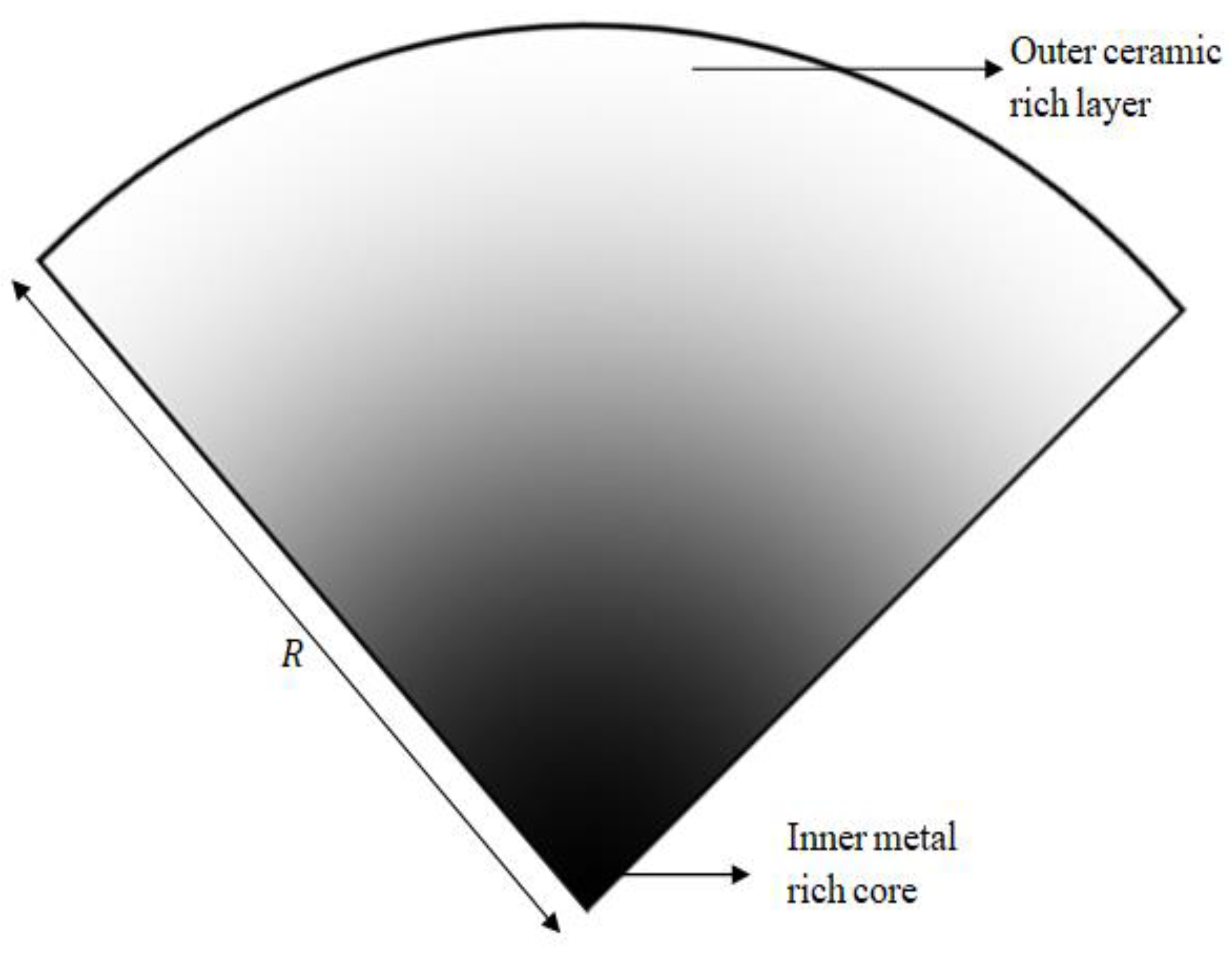
The FG rotor is composed of metal and ceramic which can be classified under metal-ceramic FGMs. The material gradation of the FG rotor occurs between the inner metal-rich core and the outer ceramic-rich layer in the radial direction, as shown in
Figure 1 based on power law. The volume fraction of ceramic is varied in the radial direction based on power law as:
The relationship between the volume fractions of the metal and ceramic constituents at any given layer of the FG rotor can be written as:
According to the rule of mixtures of composite materials, effective material properties
of a given layer of the FG rotor can be expressed as:
Solving the above three equations, effective material property for any given layer of the FG rotor can be obtained as:
The FG rotor is subjected to a temperature gradient that follows one-dimensional steady-state Fourier heat conduction equation, without heat generation, expressed below.
The boundary conditions
T =
Ti at
r =
Ri and
T =
To at
r =
Ro have been applied, and non-linear temperature distribution as a function of the radial distance from the centerof the rotor has been obtained by Lanhe [
26], expressed as a polynomial series of seven terms given below.
Here,
and
. The material properties of the metal and ceramic in the FG rotor subjected to temperature gradient vary as a function of material temperature. The material property as a function of material temperature can be expressed as:
where
P−1, P0, P1, P2 and
P3 are the temperature coefficients and are unique for a given material property of a given material. The temperature coefficients for the material properties of various materials have been listed by Reddy & Chin [
27].
4. DSM Formulation for FG Rotor Element
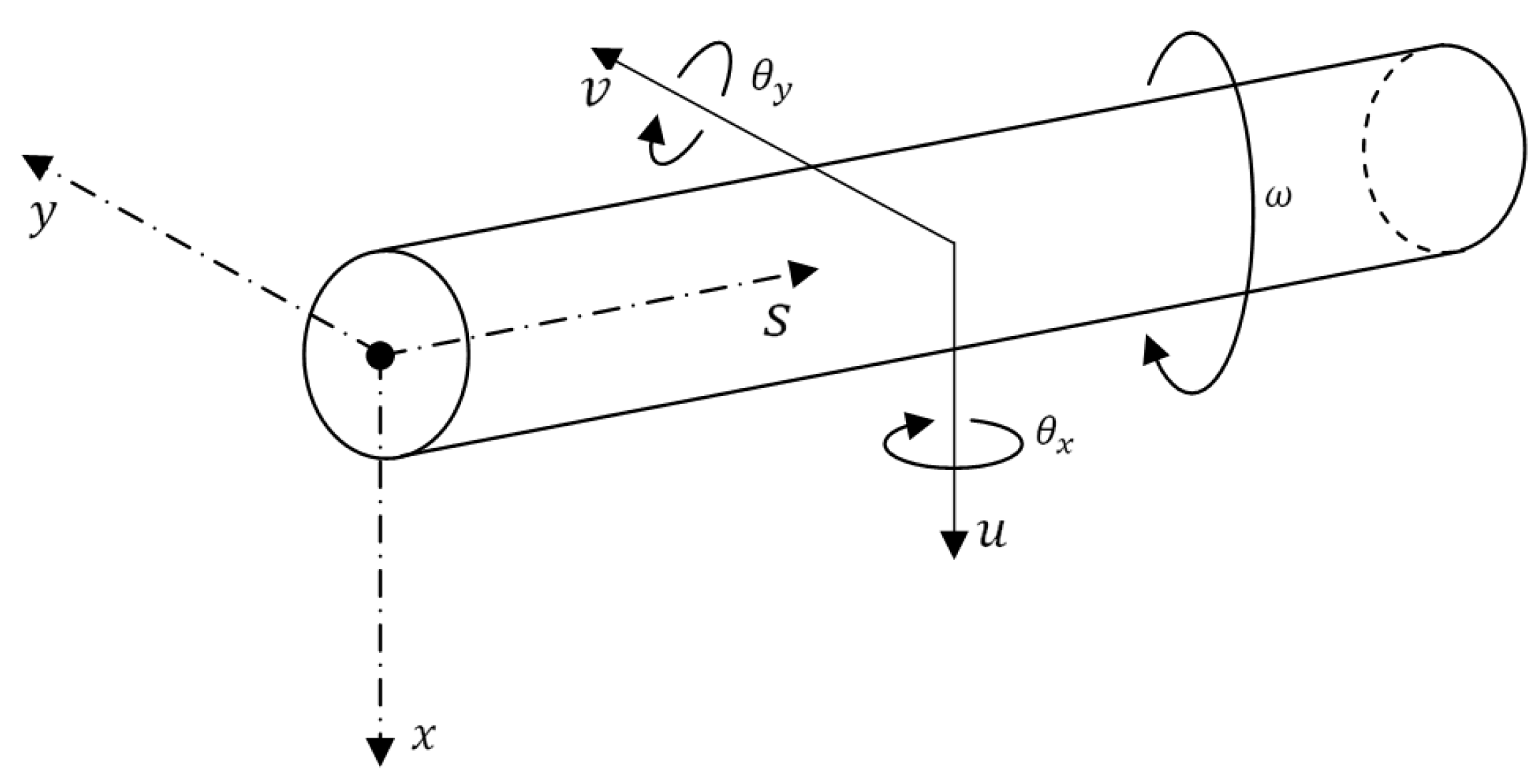
The general coordinate system (
x,
y,
s) and the nodal degrees of freedom of the FG rotor element are represented in
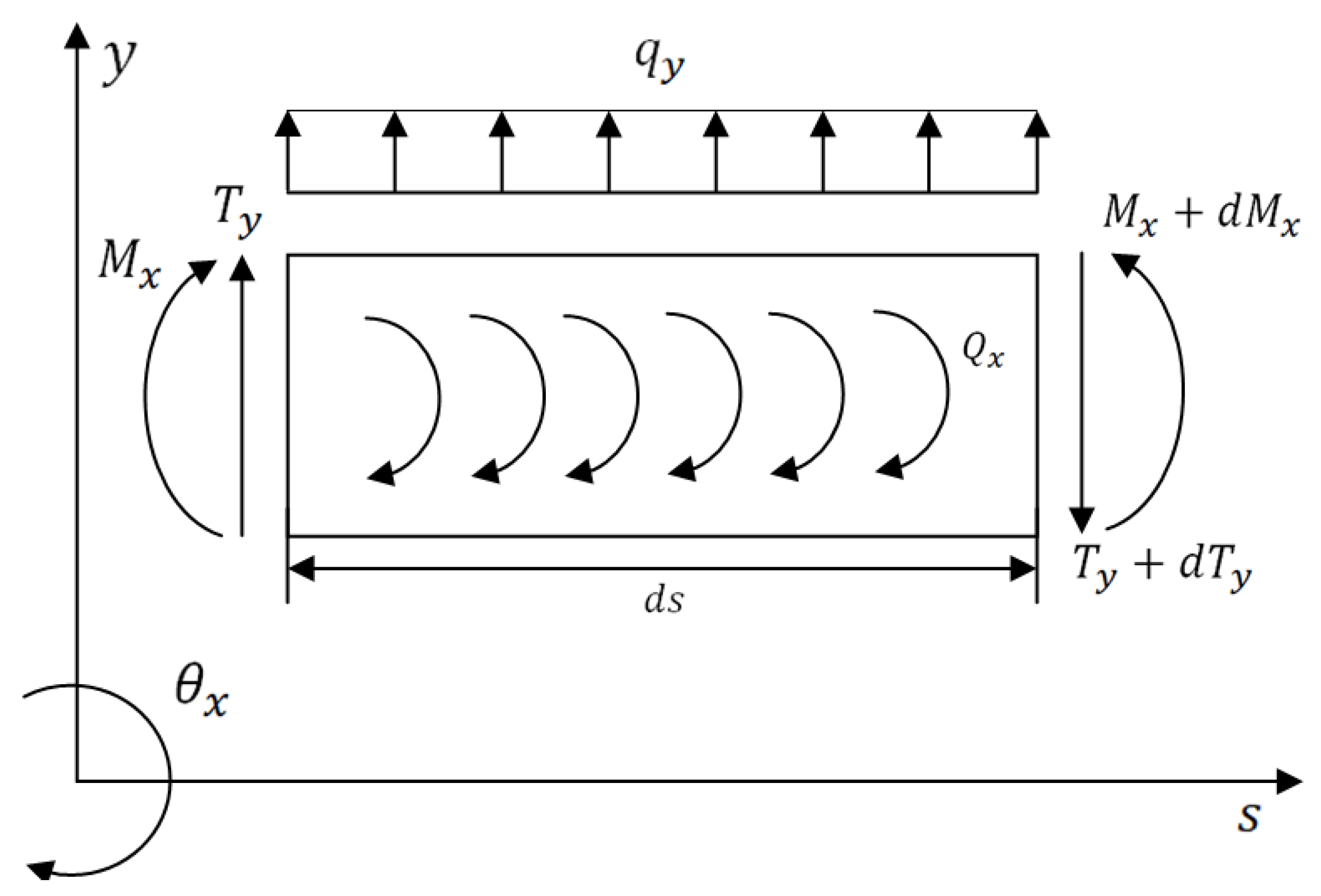
Figure 3. The loads acting on the differential FG rotor element in (
x,
s) and (
y,
s) planes at equilibrium are represented in
Figure 4 and
Figure 5, respectively. The expressions for these various loads acting on (
x,
s) and (
y,
s) planes are defined based on Timoshenko beam theory which considers the effects of translation and rotation inertia, bending and gyroscopic moment, and transverse shear. The corresponding translational and rotational equilibrium conditions in both planes have been derived.
Inplane:
The expressions for various loads acting on the plane, represented in
Figure 4, are listed below.
From Equations (8)–(11), the translational and rotational equilibrium conditions of the plane are obtained in Equations (12) and (13), respectively.
Inplane:
The expressions for various loads acting on the plane, represented in
Figure 5, are listed below.
From the Equations (14)–(17), the translational and rotational equilibrium conditions of the plane are obtained as given below, respectively.
4.1. Governing Differential Equations of Motion
The variables
θx and
θy are eliminated from the equilibrium condition equations of the planes (
x,
s) and (
y,
s) given in Equations (12), (13), (18)and (19), respectively. The resultant equations are combined by introducing a complex variable
z =
x +
iy, to obtain the governing equation for the Timoshenko FG rotor element in terms of total deflection
z as:
The variables
and
are eliminated from the equilibrium condition equations of the planes (
x,
s) and (
y,
s) given in Equations (12), (13), (18) and (19), respectively. The resultant equations are combined by introducing a complex variable
, to obtain the governing equation for the Timoshenko FG rotor element in terms of bending slope
θ as:
The structure and the coefficients of the governing equations of Timoshenko FG rotor element in terms of total deflection, and bending slope, given in Equations (20) and (21) are the same.
4.2. Solution Procedure for the Governing Differential Equations
The solution for the total deflection,
z and the bending slope,
θ in the Equations (20) and (21) for the harmonic motion of the Timoshenko FG rotor element can be assumed as
and
where
and
are the position-dependent amplitudes of motion. Substituting the assumed harmonic solutions in the corresponding equations, the Equations (20) and (21) can be rewritten as:
where,
The solution for Equations (22) and (23) can be assumed as:
Substituting the Equations (24) and (25) in Equations (22) and (23), respectively, the resultant characteristic equations can be obtained as:
where,
The two roots of the quadratic characteristic Equation (26) are:
Considering the condition
, the roots
and
can be written as:
From Equation (27), the solution for amplitude functions
and
can be expressed as:
where,
are the constants of integration.
The two sets of integration constants and in Equations (28) and (29), respectively are related to each other due to the coupling between the lateral deflection and the bending slope in both (x,s) and (y,s) planes given by the coupled equilibrium Equations (12), (13), (17)and (18), respectively. The relationship between the two sets of integration constants has been derived.
The either of the translational or rotational equilibrium equations of (
x,
s) and (
y,
s) planes canbe combined together and rewritten in terms of the amplitude functions
Z(
s) and
to derive the relationship between the two sets of integration constants. The translational equilibrium Equations (12) and (17) of (
x,
s) and (
y,
s) planes, respectively, have been considered and the following resultant equation by applying the procedure mentioned before has been obtained.
Substituting the Equations (24) and (25) in Equation (30) above, the following relationship between the two sets of integration constant has been derived,
where,
4.3. Dynamic Stiffness Matrix Coefficients
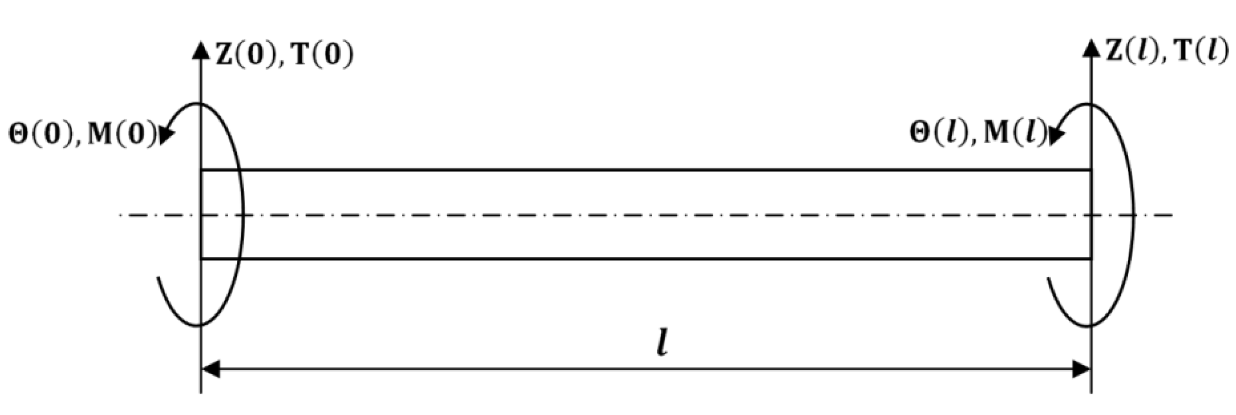
The boundary conditions of the Timoshenko FG rotor element at its ends which includes the generalized loads and displacements are represented in
Figure 6.
The relationship between the loads and displacements of the rotor element has been written in matrix form as:
Here,
K is the dynamic stiffness matrix and
are the dynamic stiffness matrix coefficients of FG rotor elements. The Equations (10) and (16) are combined to obtain the expression for
T(
s), and the Equations (11) and (17) are combined to obtain the expression for
M(
s) in terms of amplitude functions as:
The expressions for total deflection, bending slope, shear force and bending moment at the beam ends can be obtained from the Equations (28), (29), (32) and (33), respectively. Substituting these expressions in Equation (31), the expressions for the dynamic stiffness coefficients of the dynamic stiffness matrix can be derived. Looking at the expressions of dynamic stiffness matrix coefficients, the dynamic stiffness matrix appears to exhibit the asymmetric structure, the inherent property of the dynamic stiffness matrix being symmetric in nature. The symmetric structure of the dynamic stiffness matrix can be obtained by using the following identity:
In the above equation,
. The expressions of dynamic stiffness matrix coefficients of the dynamic stiffness matrix can be written as:
.
The 4 × 4 DS matrix of the FG rotor element with dynamic stiffness coefficients derived above can be used to find the natural frequencies of the FG rotor element for different boundary conditions. Any number of DS matrices of FG rotor elements of the same/different element lengths can be assembled to the required rotor length in addition to the DS matrices of uniform rigid disk and linear isotropic bearings obtained from Curti et al. [
2]. The effect of the gyroscopic moment of disk rotation has been included in the DS matrix of the uniform rigid disk. The final assembled global DS matrix can be used to find the natural whirl frequencies of the FG rotor bearing system. The reader may refer to the assembly procedure detailed in Curti et al. [
2] to possess a greater understanding in regard to the assembly procedure of DS matrices for a rotor bearing system.
6. Results and Discussions
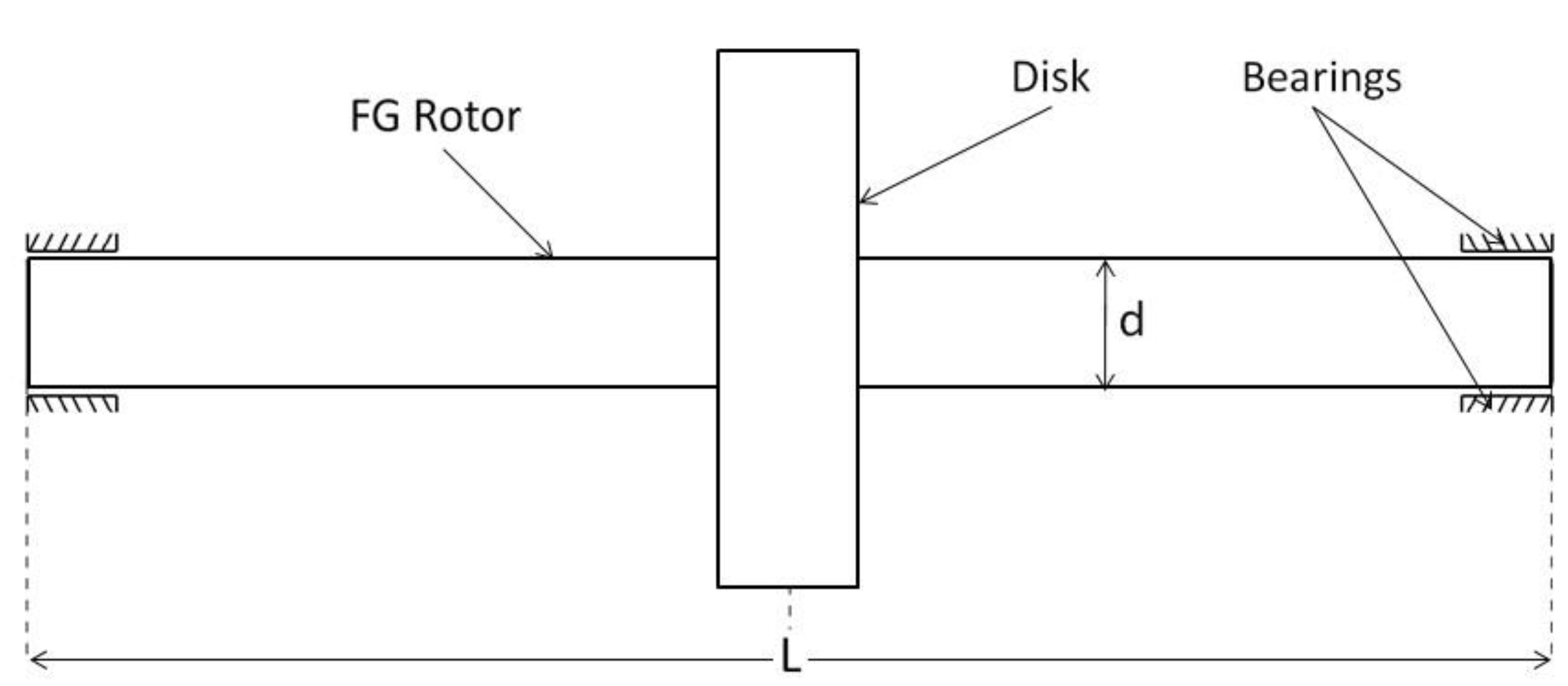
In the present study, the global dynamic stiffness matrix has been derived for the FG rotor bearing system in which the FG rotor is subjected to temperature gradients. The FG rotor consists of a uniform rigid disk at the centerand is supported on linear isotropic bearings at the ends as shown in
Figure 7. A code has been developed in Python Programming Language (PPL) to obtain the natural and whirl frequencies of the FG rotor bearing system from its global dynamic stiffness matrix developed in this paper using the Wittrick–William algorithm. The step-by-step validation procedure of the developed DSM method with the published results has been presented in the following subsections.
6.1. Validation of DSM Formulation—SteelRotor Bearing System
To begin with, the natural frequencies of the steel rotor bearing system have been computed from the global DS matrix using the Wittrick–William algorithm. The following properties of the steel rotor bearing system are used to validate the results from the literature [
28].
Steel material properties: .
Rotor dimensions: .
Bearing stiffness, .
Disk properties: .
The natural frequencies obtained from DSM are compared with FEM results and tabulated in
Table 1.The results obtained are in good agreement with the literature. The approximate mode shapes and corresponding natural frequencies obtained from the FEM method varyfrom the exact solutions obtained from the DSM method at higher modes compared to lower modes. Therefore, there is a higher variation in the natural frequencies obtained from FEM and DSM methods at mode 3 compared to the lower modes. The validation ensures the correctness of the Wittrick–William and DSM formulation for homogeneous materials.
6.2. Validation of DSM Formulation—FG Beam
Further, the exactness of the FG modeling and the corresponding DSM formulation has been ensured by validating the non-dimensional natural frequencies computed for the simply supported FG beam from the developed code. The non-dimensional natural frequencies are computed for the slenderness ratio
at different modes and for different power law indices from the developed code. The computed results are compared with results available in the literature in
Table 2. The natural frequencies are in good agreement with the published results. The beam dimensions and FG material properties used for determining the frequencies are obtained from [
21] as given below.
Beam dimensions: .
Bottom surface (steel): .
Top surface (Al2O3): .
The non-dimensional natural frequencies are computed as
Thus, the dynamic stiffness matrix formulation presented in this work can be used to carry out a free vibration analysis of the FG rotor bearing system, and the Wittrick–William algorithm can be used to determine the modal frequencies from the global dynamic stiffness matrix of the FG rotor system.
6.3. DSM Method Application to Thermally Loaded FG Rotor System
In this section, the DSM approach has been demonstrated for an FG rotor bearing system (shown in
Figure 7) subjected to thermal gradients with proper validations. The FG rotor is divided into four rotor elements with a total of five nodes. The FG rotor is made up of FGM, which is composed of metal and ceramic, as mentioned earlier in the paper in the material modeling section. The metal and ceramic materials considered for the material modeling of the FG rotor are stainless steel and zirconium dioxide, respectively. The temperature dependent coefficients for the material properties of stainless steel and zirconium dioxide are obtained from [
18] and are tabulated in
Table 3. The geometrical dimensions of the FG rotor and the properties of disk and bearings used in the present study are:
Rotor dimensions: .
Bearing stiffness: .
Disk Properties:
The first three modes of the forward and backward whirl frequencies of the FG rotor bearing system subjected to temperature gradients at the rotor spin speed 4000 rpm and inner temperature
has been computed using the dynamic stiffness method for different power law indices and temperature gradients. The computed whirl frequencies of the FG rotor bearing system subjected to temperature gradients havebeen compared with the FEM results available in [
18]. The comparison between the results from the DSM method in the paper and FEM in the literature for temperature gradients at Δ
T = 0 K, 300 K and 600 K are presented in
Table 4,
Table 5 and
Table 6.
The whirl frequencies computed from the DSM method are in good agreement with FEM results obtained from the literature. The FG rotor has been divided into ten finite elements to obtain the required convergence of the results using FEM in the literature. However, the results obtained from the DSM method have been found to be independent ofthe number of elements considered in the analysis, which exemplifies the exactness and computational efficiency of the DSM method.
7. Conclusions
The dynamic stiffness matrix formulation has been developed for the first time for the free vibration analysis of a (FG) rotor bearing system subjected to temperature gradients and to investigate its application to FG rotors. The translational and rotational equilibrium equations have been obtained by applying the equilibrium conditions to the expressions of various loads acting on the FG rotor elements. The governing equations of motion for FG rotor elements have been derived from the equilibrium equations, and the dynamic stiffness matrix has been developed for the same. The Wittrick–William algorithm has been employed as a root searching technique to compute the natural frequencies from the global DS matrix.
The dynamic stiffness matrix formulation code has been thus developed to carry out the free vibration analysis of FG rotor bearing systems. The correctness of the dynamic stiffness matrix formulation has been ensured with the validation of the results obtained from the DSM code, with the results available in the literature. The natural whirl frequencies of the FG rotor bearing system subjected to temperature gradient have been obtained from the DSM code and compared with the FEM results available in the literature. The exactness of the DSM method has been exemplified as the results obtained from the method have been found to be independent of the number of the FG rotor elements considered, which saves a significant amount of computational time.
The authors’ believe that the current article is a step in the right direction in the accurate analysis of complex systems made up of FGMs in the broader view of applications in engineering. The developed DSM method can be used to study the vibration behavior of systems used in various applications, such as micro/nano applications and so on, re-modeled using functionally graded material to investigate its possible application in those systems.


