Article

Method of Data Selection for Turning of Inconel 718 Alloy Obtained by Casting and Laser Sintering Powder

by
Ksenia Latosińska
1,*,
Grzegorz Struzikiewicz
2 and
Wojciech Zębala
1
1
Chair of Production Engineering, Faculty of Mechanical Engineering, Cracow University of Technology, 31-864 Cracow, Poland
2
Chair of Manufacturing Systems, Faculty of Mechanical Engineering and Robotics, AGH University of Science and Technology, 30-059 Cracow, Poland
*
Author to whom correspondence should be addressed.
Materials 2022, 15(4), 1448; https://doi.org/10.3390/ma15041448
Submission received: 14 January 2022 / Revised: 7 February 2022 / Accepted: 11 February 2022 / Published: 15 February 2022

Abstract

:
This article focuses on the issues related to the machining of DMLS (Direct Metal Laser Sintering) laser sintered parts made of Inconel 718 alloy. Longitudinal turning with CBN (cubic boron nitride) tool inserts is analyzed. The authors made an attempt to establish a procedure to find the optimal finishing cutting parameters while minimizing the specific cutting force and taking into account the machined surface quality criterion. During experiments the influence of cutting data on the values of cutting force and specific cutting force were performed. Moreover, the results of measurements of surface roughness parameters and the results of analysis of chip form are presented as well. Cast Inconel 718 has also been tested for comparative purposes. The variability of the material’s hardening state during machining was found, as well as the variability of the specific cutting force value as a function of the cross-sectional shape of the cutting layer. The values of all components of the total cutting force for turning the material obtained by the additive method are lower than for turning the cast material by approximately 32%. At the end of the article, the authors present an application of the proposed optimization algorithm. It was established that by changing the cross-section shape of the cutting layer, it was possible to perform the turning process at a specific cutting force value of 22% less, which is achieved by reducing the cross-section size.

1. Introduction

Nickel-cobalt-based alloys, and Inconel 718 in particular, are one of the most widely used superalloys in the aerospace and energy industries today. They are used in the production of aircraft engine parts and in the energy industry due to their unique properties such as resistance to high temperatures, good thermal fatigue properties, corrosion resistance, and good mechanical properties in extreme conditions [1,2]. These materials constitute about 50% of the components of the gas aircraft engine due to their unique properties [3,4]. Characteristic features of alloys based on nickel and cobalt include high hardness, a tendency to react with the tool (the formation of built-up edges on the blade), high strength at high temperature, low thermal conductivity, the ability to strengthen in the cutting zone and, as a result, the hardening of the alloy in the top layer [5,6]. When processing these type of materials, special attention is paid to the quality of the surface and the cohesion of the surface layer of the parts, as it affects their durability, functionality and fatigue strength. Optimization of the treatment of such materials is considered in terms of surface roughness, maximization of the cutting edge service life, and minimization of production costs [7,8].
The main methods of forming the Inconel 718 alloy are forging, casting and sintering [9]; thanks to the sintering technology, both raw material and energy can be saved; furthermore, the sintered elements are characterized by good mechanical properties and precision [10]. The production of materials using the additive manufacturing method (AM) consists of the production of objects based on the execution of a three-dimensional computer model (3D CAD) followed by the application of accumulated layers of material using various methods. AM technologies allow for the production of very complex and intricate shapes with relatively high accuracy and a high degree of structure densification [11,12]. This method allows us to shorten the production time of materials and reduce their costs [13] while maintaining their characteristic features [14,15]. The DMLS method (Direct Metal Laser Sintering) is an incremental method that melts successive layers of metal powder with a laser beam in an inert gas atmosphere which is filled with the sintering chamber in order to minimize the oxidation process of the metal powder [16]. Inconel 718 is a complex material intended for machining in AM processes because it contains a large number of alloying elements and is a precipitation strengthened alloy [17,18]. The structure and microstructure of alloys made of metal powders is different than that of cast alloys [19]. There are residual stresses that can be mitigated by various in-process methods such as heating, process planning, feedback control and post-processing (e.g., machining and heat treatment) [20]. The authors are trying to improve the sintering process of nickel-based alloys by modifying parameters such as pressure, temperature and the electric field [21].
Inconel 718 belongs to the group of difficult-to-cut materials (superalloys). Thakur et al. [22] described the influence of cutting parameters and tool wear on the surface condition of the material after machining. They noticed that the surface roughness is closely related to changes in the structure as a result of high temperatures in the machining zone (grain growth) and mechanical strains (strain hardening and DRX). They demonstrated that most surface defects appearing during machining (deformed grains, crack-king, debris, feed marks, carbide particles, surface cavities, adhered material particles, surface plucking, slip zones, and redeposited materials) are the result of improper selection of machining parameters and excessive tool wear. Residual stress studies and simulations for the treatment of Inconel 718 have already been carried out in many previous studies. The residual stresses along with the cutting parameters are influenced by the hardening speed (cold work) and the yield point resulting from the preload [23,24]. The trends of these changes differ depending on the increase in feed, depth of cut and cutting speed [25,26]. Many authors have studied the influence of various machining parameters on the obtained final results of the experiments, and they have shown the following dependencies.
Hua et al. [27] investigated the influence of the direction and magnitude of the main residual stress on the fatigue strength of the turned Inconel 718 alloy. They showed that the main residual stress is much greater than the residual surface stress and that it increases with increasing feed. They found that the main residual stresses had the greatest influence on the fatigue properties of the turned alloy. Peng et al. [28] examined the residual stresses on the surface of the turned Inconel 718 alloy. They showed that with the increase of the feed, the cutting forces increased regardless of the value of the cutting speed, and simultaneously, with the increase of the depth of cut, the cutting forces increased, but at high cutting speeds they were lower than with low cutting speeds. Hua et al. [29] investigated the effect of cutting speed, feed rate and nose radius on roughness, microhardness and the degree of work hardening of Inconel 718. They showed that an increase in the feed rate generated greater cutting force and a greater degree of material compaction. Cutting speed did not significantly affect the surface roughness as opposed to the feed rate and the nose radius of the cutting edge. The use of larger corner radii reduced the degree of work hardening and the fatigue crack propagation threshold. ČEP et al. [30] checked the influence of cutting parameters as well as manufacturing technology on the surface structure of the material after the turning process. Other authors have also studied the effect of cutting speed and other machining conditions on the surface condition after turning for nickel-based alloys made with various manufacturing technologies. Numerous authors focus on studying the effects of parameters such as feed, cutting speed, tools on the microhardness and roughness of the machined surface in the turning process [31,32].
Currently, there are no dedicated procedures for optimizing the machining of sintered materials, including the sintered Inconel 718 alloy. The authors made an attempt to establish a procedure to find the optimal finishing cutting parameters for laser sintered powder nickel-cobalt alloy while minimizing the cutting resistance and taking into account the machined surface quality criterion. An analysis of the machining of the longitudinal turning of a part made of cast and sintered Inconel 718 was carried out.
The article is organized as follows: Section 1 provides an introduction. The tests and analysis are presented in Section 2 (materials and experiments), while Section 3 describes the algorithm for the turning process of the Inconel 718 alloy and shows the application of the created algorithm. Section 4 presents the conclusions.

2. Materials and Experiments

As part of the study of the finishing process of laser sintered powder Inconel 718, an attempt was made to determine the effect of cutting parameters on the specific cutting resistance. Cast Inconel 718 was also tested as a comparison.
DMLS samples were made using a Renishaw AM 250 (Renishaw, Wotton-under-Edge, UK). The following parameters were used to prepare the samples: power 185 W, speed 289 mm/s, exposure time 100 µs, distance between sintering points 65 µm, distance between transition lines 0.13 mm, layer thickness 50 µm. The mechanical properties of the material and the chemical composition are presented in Table 1 and Table 2.
While testing, the components of the cutting forces, the roughness of the machined surface and the form of chips obtained in the process were measured. A Talysurf Intra 50 profilographometer by Taylor Hobson (Leicester, UK) was used for the measurements. Microscopic analysis of the machined surface was performed using a microscope by Bresser (Advance ICD, Bresser, Rhede, Germany). In order to record and analyze the components of the cutting forces, a measuring track was used, built on the piezoelectric dynamometer 9257B and amplifier 5070B by Kistler (Winterthur, Switzerland). The measurement of the maximum temperature value in the machined zone was carried out with the use of the SC620 thermal imaging camera and the ThermaCam Researcher program by Flir Systems (Wilsonville, OR, USA).
The SDJCR1616H11 holder from MMC Hardmetal (Group Company of Mitsubishi Materials Corporation) (Tamworth, UK) with cutting inserts made of BN2000 CBN from Sumitomo (Tokyo, Japan) was applied. The cutting parameter values are within the range recommended by the tool manufacturer.
Based on the adopted research plan, the components of the total cutting force during longitudinal turning of cast and printed Inconel 718 alloy were measured. The influence of the cross-section of the cutting layer AD on the values of the components of the total cutting force, i.e., main Fc, feed Ff and back Fp, as well as specific cutting force, was analyzed. The cross-section of the cutting layer was a function of variable cutting parameters, i.e., feed f and depth of cut ap. All trials and measurements were conducted three to five times.
Specific cutting force kc is defined as the ratio of the main cutting force Fc to the cross-section area of the cutting layer AD (1).
k c = F c A D = F c f · a p   [ N / mm 2 ]
For materials of different groups (with a different chemical composition and structure) with the same tensile strength, the specific cutting force may change. Inconel 718 is a specific example because it hardens upon treatment. The value of the specific cutting force depends on the value of the cross-section AD. In order to determine the influence of the shape of the cross-section of the cutting layer on the value of the specific cutting force kc, two types of experiments were carried out. In the first case, tests of longitudinal turning of a tapered surface were carried out, i.e., at a constant value of the feed f and variable value of the depth of cut in the range ap = <0, 1> mm. In the second case, specific cutting force tests were carried out for various shapes of the cross-section of the cutting layer, maintaining a constant value of the cross-section AD. Figure 1 shows schematically the changing shape of the cross-section of the cutting layer with a constant value. The change in the shape of the cutting layer cross-section results from the selection of the proportions of the dimensions describing the cross-section of the cutting layer, i.e., the feed f and the depth of cut ap.
Figure 2 shows the trends of cutting forces Fc, Ff, Fp and specific cutting forces kc, k_Ff, k_Fp when turning the conical surface of a shaft made of cast Inconel 718. In this case, the depth of the cut ap, which changed in time during the turning, resulted in changing the cross-section of the cutting layer. Cutting tests were carried out at a constant feed f = 0.115 mm/rev, and the cutting speed vc = 50 m/min. The cutting force curves were characterized by a constant value increase during machining for all components of the total cutting force (Figure 2a). The specific cutting force values presented in Figure 2b decreased during the cutting process with the increase of the cutting depth ap and, consequently, with the increase in the cross-section of the cutting layer AD. It was observed that for turning above the specific value of cutting layer cross-section AD > 0.04 mm2 k_Ff and k_Fp, specific cutting forces are almost constant. Based on the analysis of the trends of total cutting force components, local increases in the values for the main force Fc and the back force Fo were observed, which is shown in detail in Figure 2c. The reason for this phenomenon may be the increasing degree of hardening of the processed material in the surface layer resulting from the performed work of the cutting edge. An additional factor may be the influence of the nose radius of the cutting insert rε on the reaching of the minimum cross-section of the cutting layer above which the material decohesion occurs.
In the next stage of the research, the influence of the shape of cross-section of the cutting layer on the values of the components of the total cutting force and specific cutting force was analyzed. Figure 3 shows the characteristics of the components of the total cutting force Fc, Ff, Fp as a function of the constant cross-section of the cutting layer AD = 0.8 mm2 in 3D printed and cast Inconel 718 alloy.
Based on the analysis of the obtained results, it can be stated that the values of all components of the total cutting force for turning the material obtained by the additive method are lower than for turning the cast one. It was observed that the value differences increase above w > 0.15, which describes the ratio of feed f to depth of cut ap. For a ratio of w < 0.15, the values of the cutting forces when turning cast and laser sintered material are similar for all components. This means that the greatest differences in the values of the cutting force components are in the case of machining with small depths of cut and high feed values. For example, the values of the main cutting force Fc for turning cast alloy differ by 32% from the value for turning laser sintered material for w = 0.35, i.e., the feed f = 0.173 mm/rev and the depth of cut ap = 0.5 mm.
Similar trends as for the characteristics of cutting forces were observed for the corresponding specific cutting forces. Figure 4 shows the characteristics of the specific cutting force kc, k_Ff, k_Fp for the components of the total cutting force Fc, Ff, Fp, respectively, for turning the 3D printed and cast Inconel 718 alloy.
A comparative analysis of the cutting force for the case of increasing values of the cross-section of the cutting layer AD showed an increase of all components, which are characterized by a constant difference between the values. Figure 5 shows the components of the total cutting force Fc, Ff, Fp as a function of the constant cross-section of the cutting layer AD = 0.8 mm2 and AD = 1.2 mm2 when turning the 3D printed Inconel 718 alloy. A decrease in the Fc and Fp components was observed for increasing values of the w parameter. On the other hand, the values of the feed component Ff increase for each value of the section of the cut layer (Figure 5b).
Figure 6 shows the graphs of the specific cutting force kc, k_Ff, k_Fp for the components of the total cutting force Fc, Ff, Fp respectively, when turning laser-sintered material for two values of the cross-section of the cutting layer, i.e., AD = 0.8 mm2 and AD = 1.2 mm2. The specific cutting force kc and kcp decrease with an increase of the parameter w (Figure 5a,c) for both analyzed sections. It should be noted that the values of the specific cutting force for the bigger cross-section AD = 1.2 mm2 are lower for w parameter range <0.3 than for the cross-section with the lower value. For w ≈ 0.3, the values of the specific cutting force kc reach similar values. Above the value of the parameter w ≈ 0.3, the specific cutting force for the cross-section AD = 1.2 mm2 is higher. It seems that by changing the shape of the cross-section of the cutting layer, the turning process can be carried out with reduced specific cutting force values. It is important for the selection of machining allowances and for the implementation of turning, both fine and rough. It should be noted, however, that changing the shape of the surface reduces the volumetric efficiency of the Qv process, which results in an extension of the total cutting time Ttotal.
Figure 7 shows the surface roughness profile Ra for turning of the cast and 3D printed Inconel 718 alloy. In all cases, the surface roughness values increased. This is the result of increasing values of the feed f in order to maintain a constant cross-section of the cutting layer, i.e., with decreasing values of the depth of cut ap. It should be noted, however, that when turning laser sintered material, the surface roughness Ra was lower than when turning cast material.
Figure 8 shows examples of photos of chips obtained by turning a laser sintered and cast alloy. In the case of turning the laser sintered alloy, an acceptable chip shape was obtained with a length in the range of Lch = <30; 60> mm. The following chip classification has been adopted: “-”-unacceptable chips with a length of more than 150 mm; “0”-acceptable chips with a length of 30–150 mm and favorable chips “+” with a length of up to 30 mm. The obtained chips were spiral and continuous. A slight change in the chip shape was observed for increasing the feed f. For turning the cast Inconel 718, usually chips were obtained with an unacceptable shape with a length above Lch > 150 mm. The obtained chips had the form of a long, twisted or spiral ribbon. A change in the chip shape from ribbon to spiral was observed for increasing feed f values while maintaining a constant cross-section of the cut layer AD = 0.08 mm2. For a higher value of the cross-section of the cutting layer AD = 0.12 mm2, an advantageous shape of chips was observed when turning the DMLS printed material. In the case of turning cast material, the chips were classified as disadvantageous or acceptable.

3. Description of Algorithm for Turning Data Selection and Application

Figure 9 shows a simplified diagram of the procedure algorithm which is used for turning as the method of minimizing the value of the specific cutting resistance kc. The minimization of the kc parameter value is performed taking into account the constant value of the area of cross-section of the cutting layer AD. In turn, the value of the area of cross-section of the cutting layer is determined by selecting the suitable ratio the value of the feed f and the cutting depth ap (schematic presented in Figure 1). The shape of the cross-sectional area of the cutting layer also depends on the corner radius of the cutting insert and the entering angle κr of the applied cutting edge. The method takes into account the optimization constraints as permissible values of specific cutting resistance kc_limit, surface roughness Ra_limit, w_limit, the coefficient describing the ratio of the feed value and cutting depth and the maximum temperature in the cutting zone, Tmax_limit.
The following steps are executed in the procedure algorithm presented in Figure 9a:
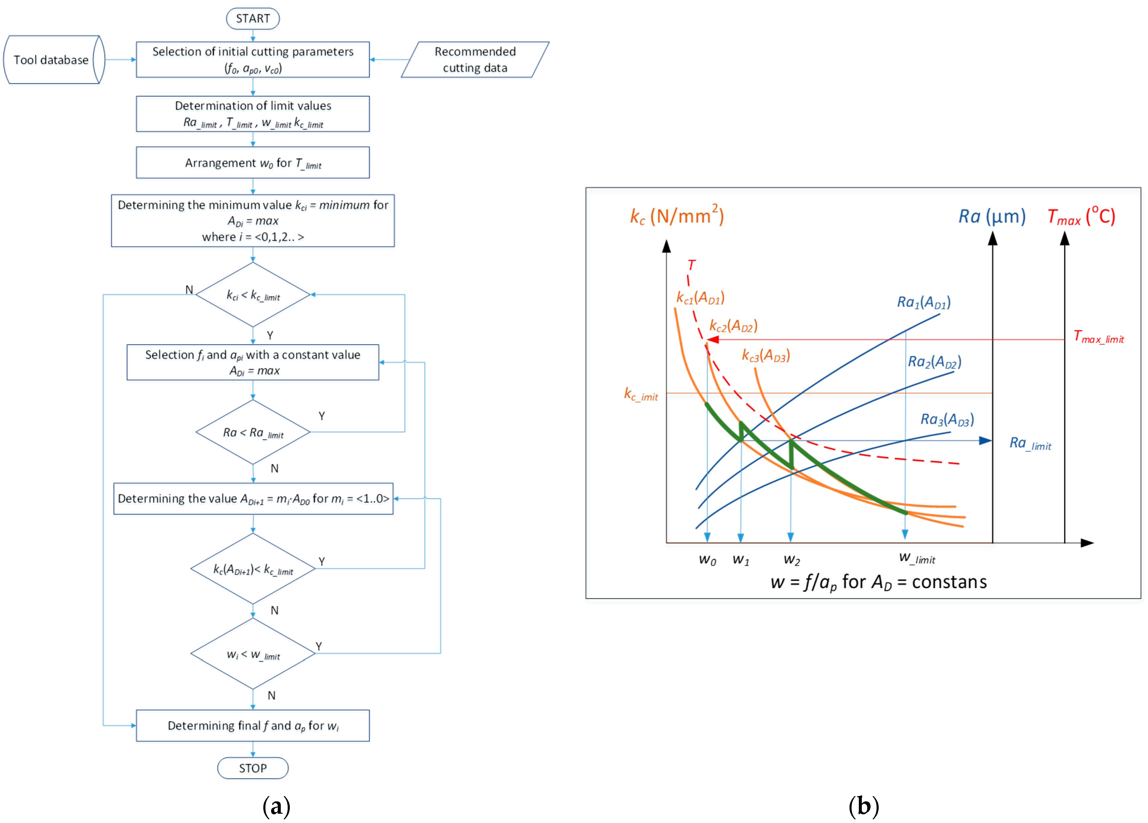
  • In the first step, the initial turning conditions are adopted, including the selection of the cutting tool. Based on that, the initial ranges of the values of the cutting parameters (f0, ap0, vc0) are adopted and the AD0 area of cross-section is determined.
  • In the next step, acceptable values of limiting parameters are adopted, i.e., kc_limit, Ra_limit, wlimit and Tmax_limit.
  • In the next step, the initial value of the parameter w0 = f/ap is determined for the adopted Tmax_limit value.
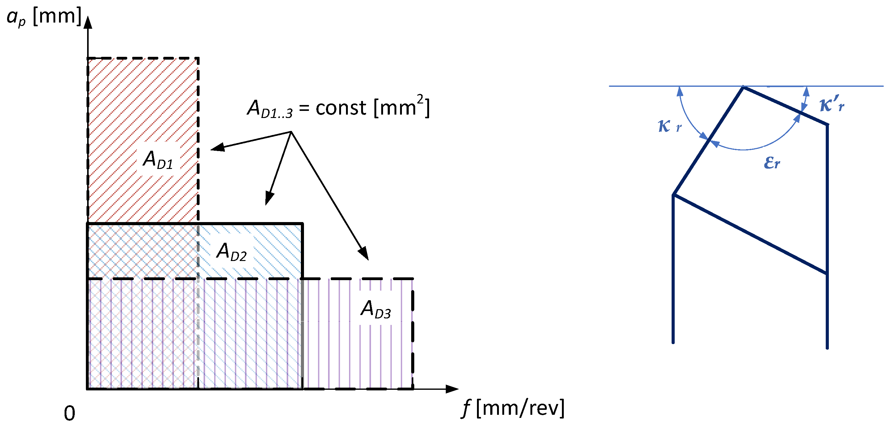
  • The maximum value of the AD area of cross-section is determined for which it is possible to obtain the minimum value of the kc specific resistance during turning. It also means setting the value of the parameter w depending on the feed f and the cutting depth ap in ratio allowing for the maintaining of a constant value of AD = const. This is done by suitable increasing of the feed value and by decreasing the value of the cutting depth.
  • In the next stages of the procedure algorithm, the actual cutting resistance is checked to see whether it exceeds the allowed values, kc_limit and Ra_limit. In the case when the condition Ra < Ra_limit is not met, another value of AD is determined, or a correction of the value AD = m·AD is adopted. Assuming the value of the correction factor m in the range m = <1..0> means that a smaller value of the AD parameter is searched for which a constant value of the parameter w is preserved. At the same time, the condition of exceeding the kc_limit limit is checked for the determined correction value.
  • As a last step, the condition of exceeding the w_limit value is checked, based on which the final values of the feed and the cutting depth are adopted and the turning is performed.
Figure 9b shows a schematic representation of the implementation steps of the method of minimizing the value of the actual cutting force.
An exemplary algorithm application is presented for turning a shaft made of Inconel 718 with the use of the DMLS method. The following ranges of cutting parameters and acceptable limits were assumed: ap = <0.5; 1.0> mm, f = <0.086; 0.25> mm/rev, vc = 50 m/min, kc_limit = 4000 N/mm2, Tmax_limit = 600 °C, w_limit = 0.35 and Ra_limit = 1.2 µm. Figure 10 shows the characteristics of the specific cutting force kc, surface roughness Ra and the maximum temperature in the cutting zone Tmax as a function of the w parameter for two values of the cross-section AD1 = 0.086 mm2 and AD2 = 0.12 mm2. The figure shows the correct characteristics of specific cutting force, surface roughness and maximum temperature. The adopted limits are marked with horizontal and vertical sections.
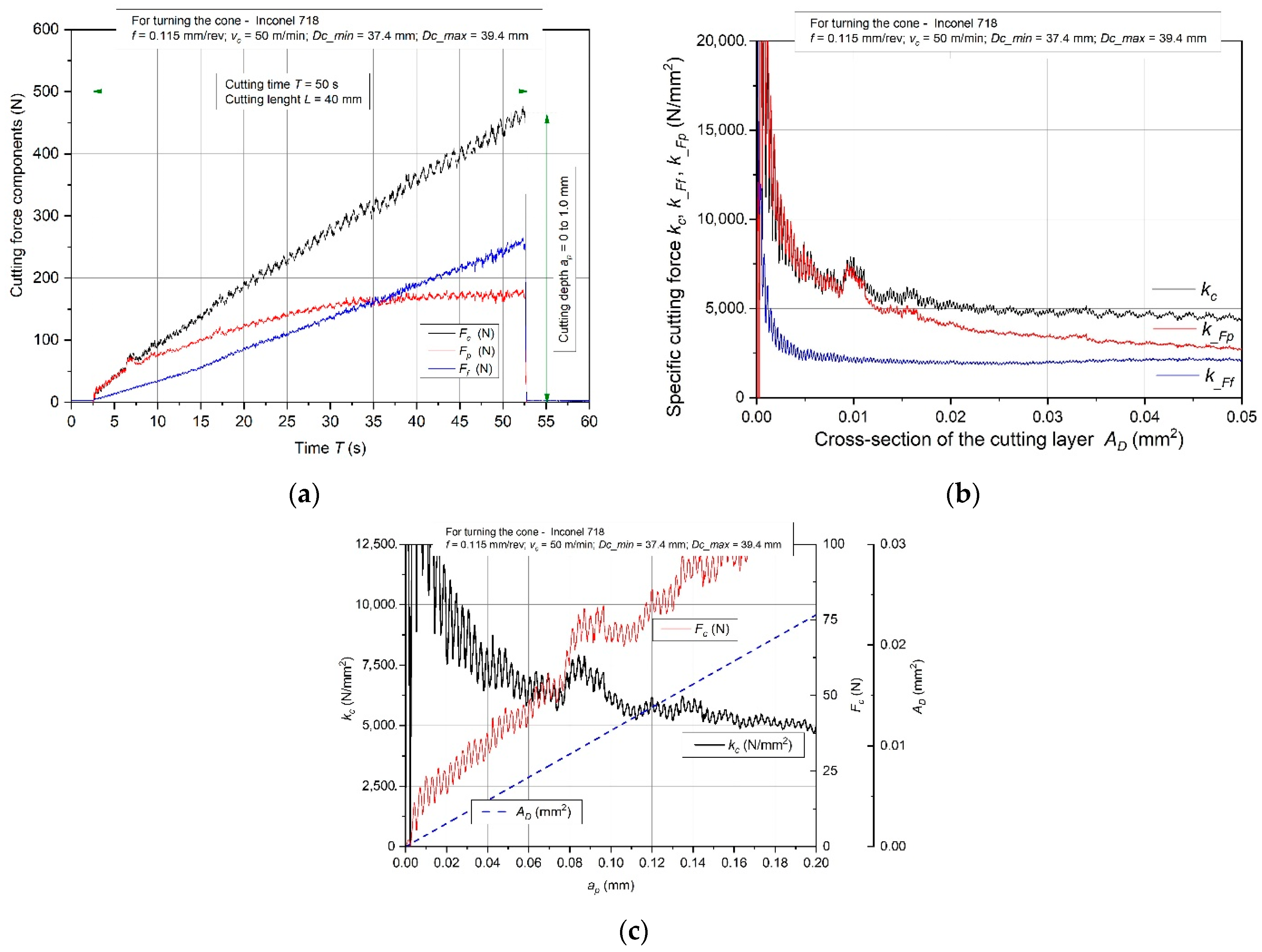
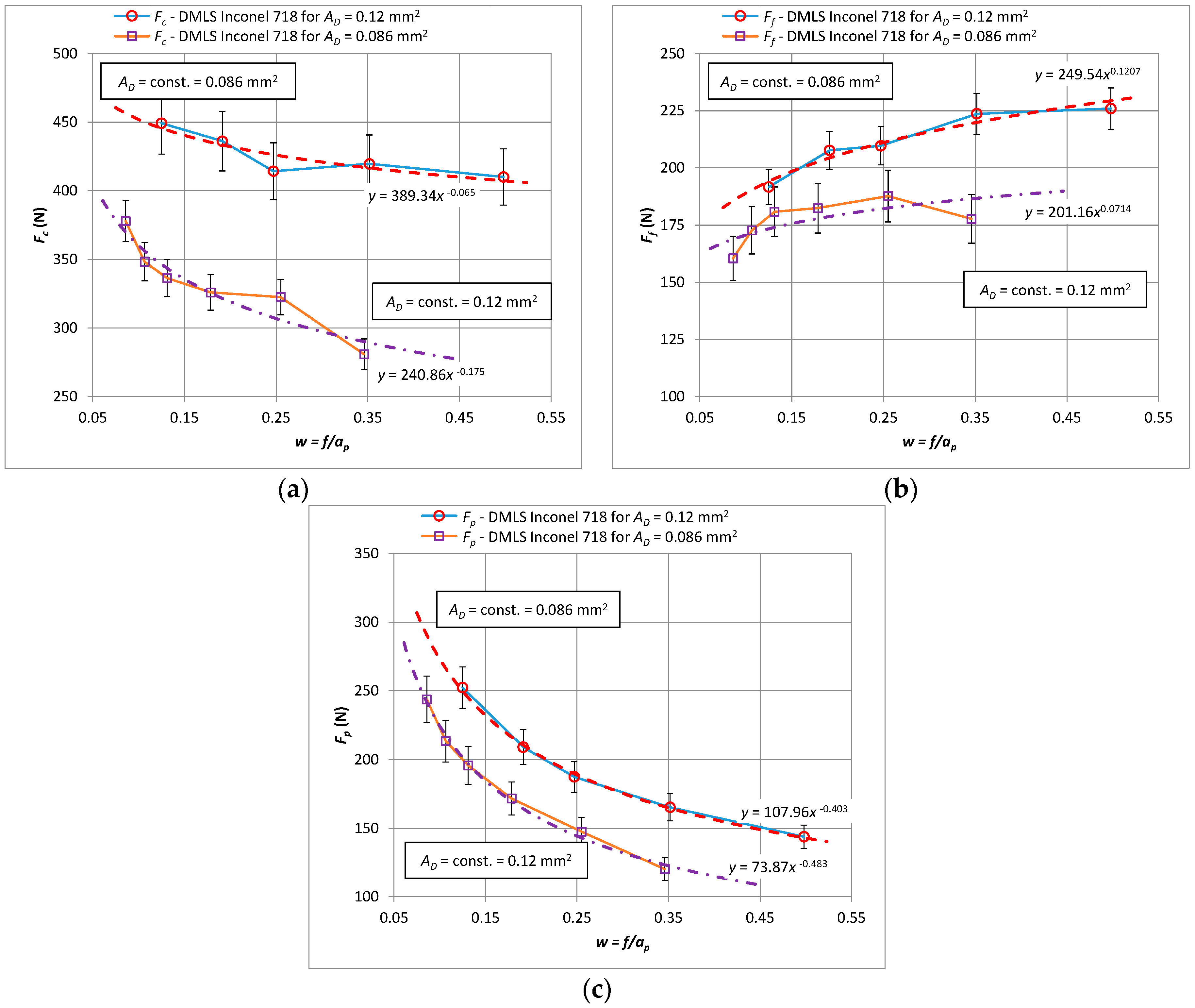
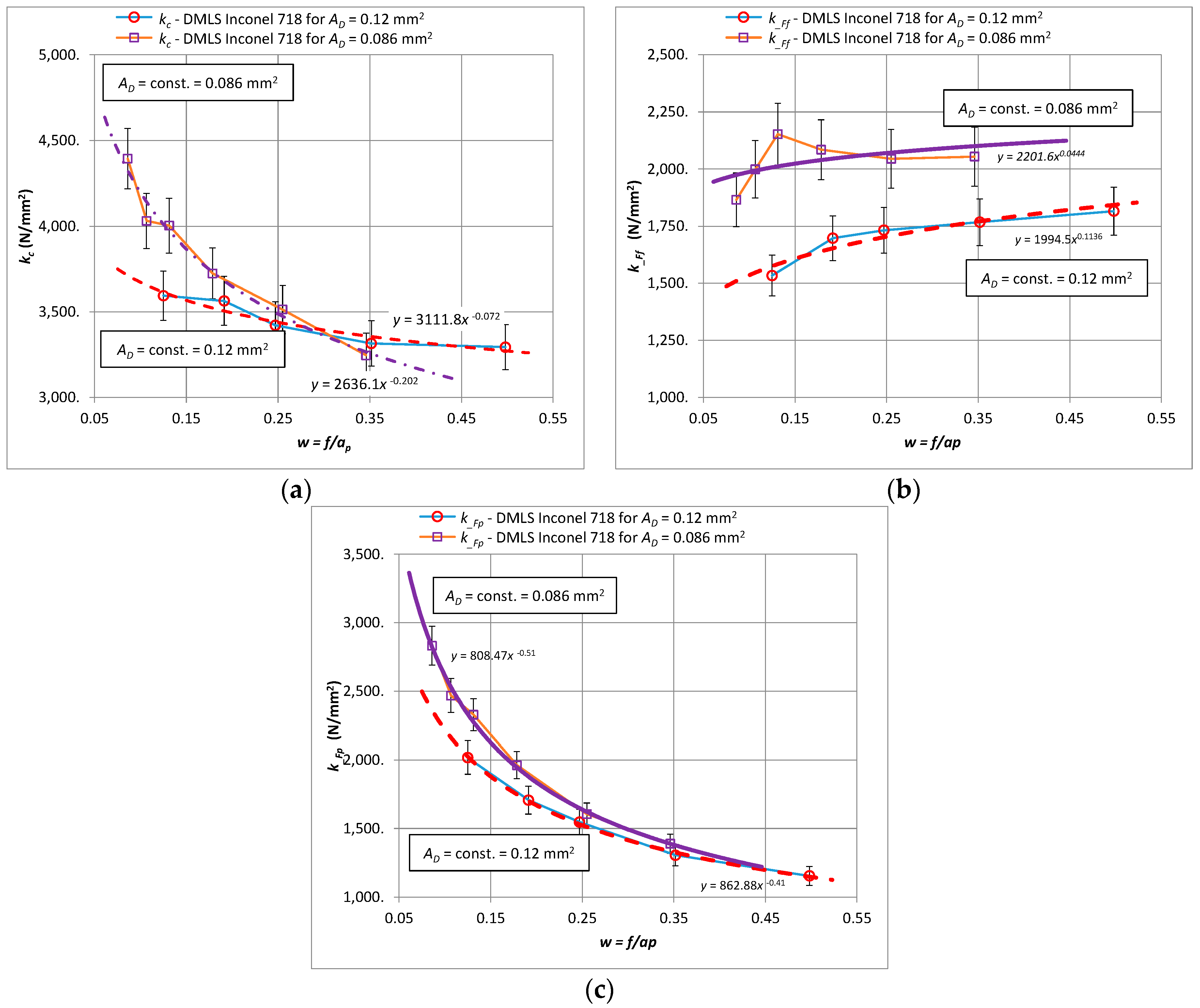
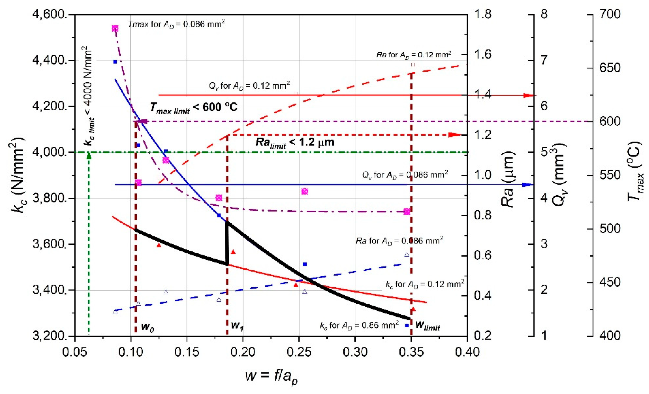
According to the algorithm (Figure 9), for Tmax_limit = 600 °C, the initial value of w0 = 0.15 was set. For such w0 value the lowest value of the specific cutting force kc is for the cross-section AD2 = 0.12 mm2.
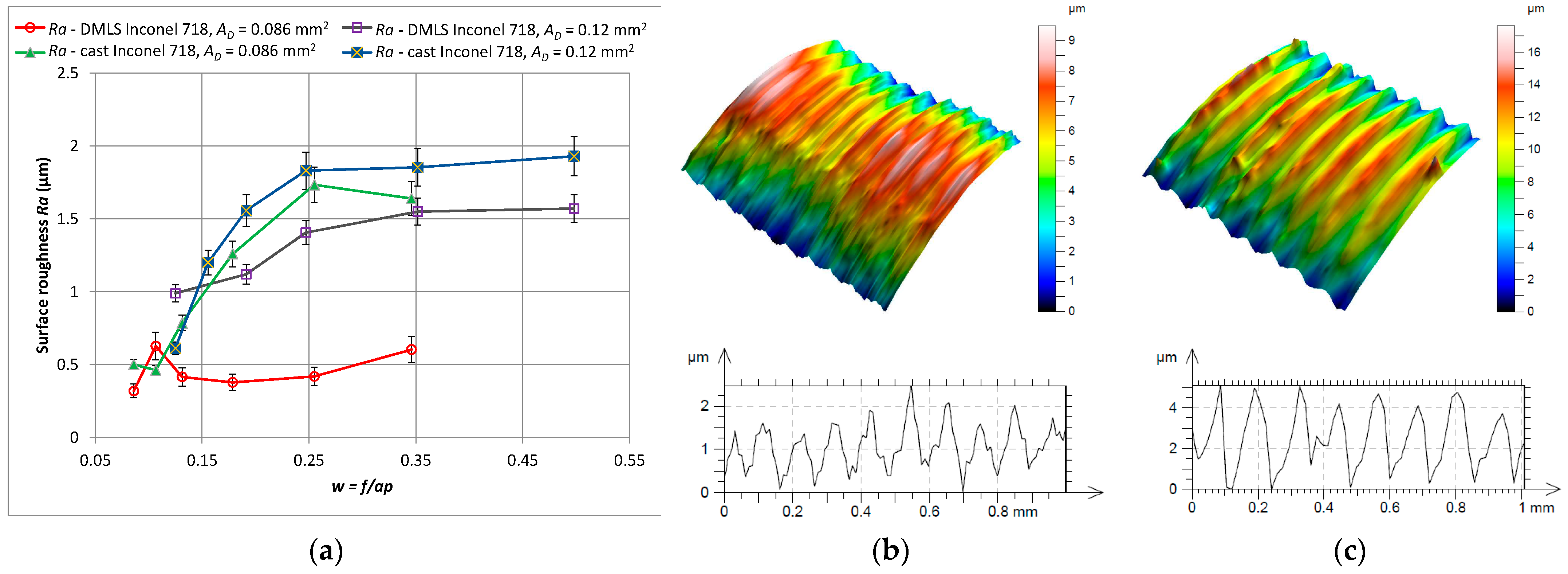
For such initial conditions, the lowest value of kc may be obtained via selection of the feed f (higher f value) and depth of the cut AD2 = 0.12 mm2. For such assumed initial conditions, the minimization of the kc value can be achieved by selecting the feed value f (i.e., increasing the f value) and the cutting depth ap (i.e., reducing the ap value) while maintaining the constant value AD2 = const. For the value w1 = 0.186 the smaller value of the cross-section AD1 = 0.086 mm2 should be assumed due to the exceeding of the permissible surface roughness Ra_limit = 1.2 µm at this point.
Further minimization of the kc value is achieved by appropriately (proportional) increasing the value of the feed and at the same time reducing the value of the cut of depth while maintaining a constant value of AD1. The surface roughness characteristics Ra for AD1 = 0.086 mm2 shows that in this case all surface roughness values are lower than the accepted limit Ra_limit = 1.2 µm. Therefore, the determination of the optimal cutting parameters will result from the adopted limiting value w_limit = 0.35. In this case, the optimal values will be: feed f = 0.175 mm/rev and cutting depth ap = 0.5 mm. However, it should be noted that adopting a smaller value of the cross-section of the cutting layer causes a reduction in the volumetric efficiency of the turning process Qv (which results from adopting a constant cutting speed value vc = 50 m/min). Maintaining the efficiency for the initial cutting data can be achieved by adopting a correspondingly higher cutting speed vc.

4. Conclusions

Based on the obtained results and the conducted analysis, the following conclusions can be made:
Based on the developed algorithm for turning with a shape of the cross-section of the cutting layer, which changes in time, the machining process can be carried out with reduced specific cutting force values. The algorithm has been experimentally verified for the turning of laser sintered Inconel 718 alloy and can be perceived as a guideline for the mechanical processing of parts obtained by 3D printing.
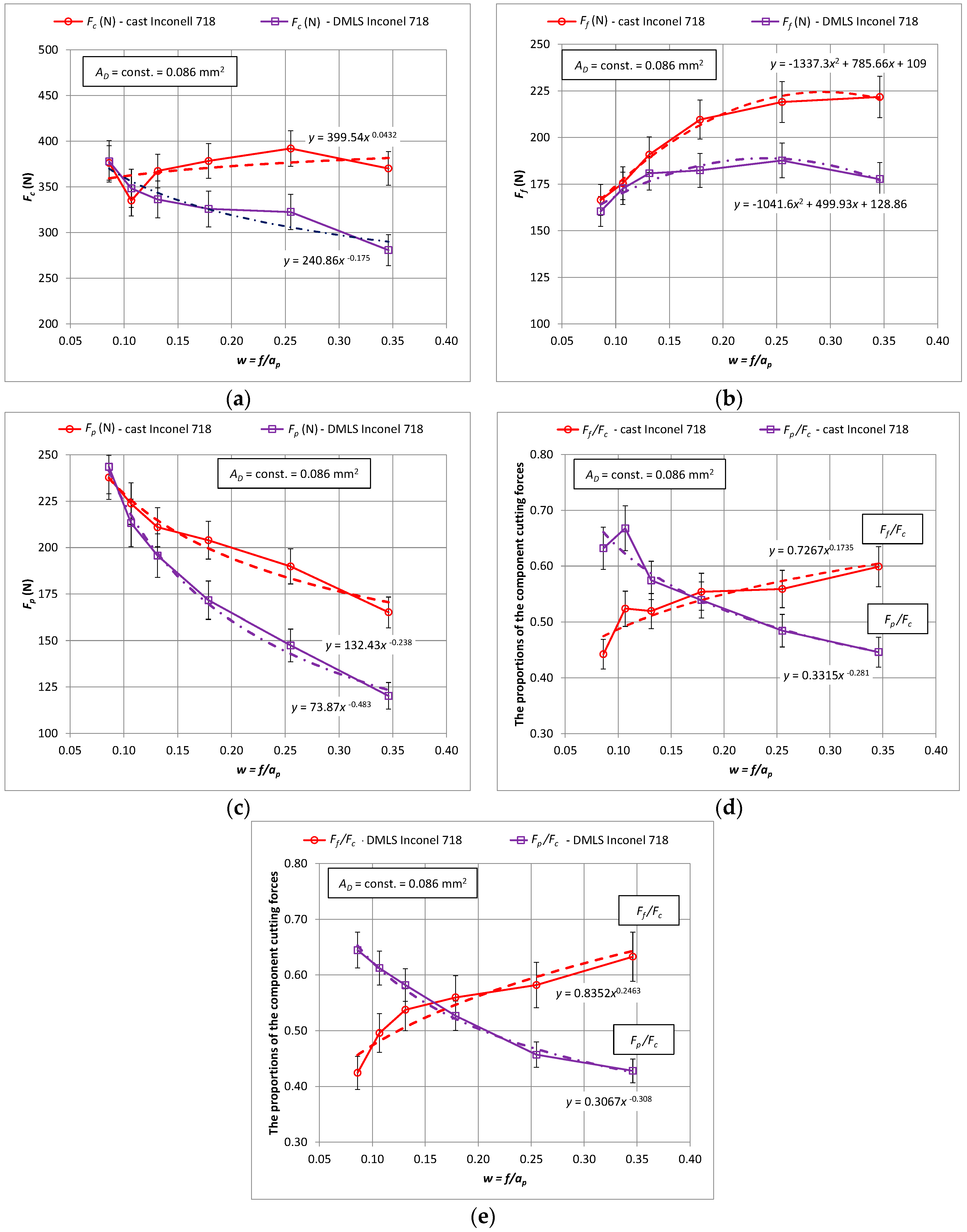
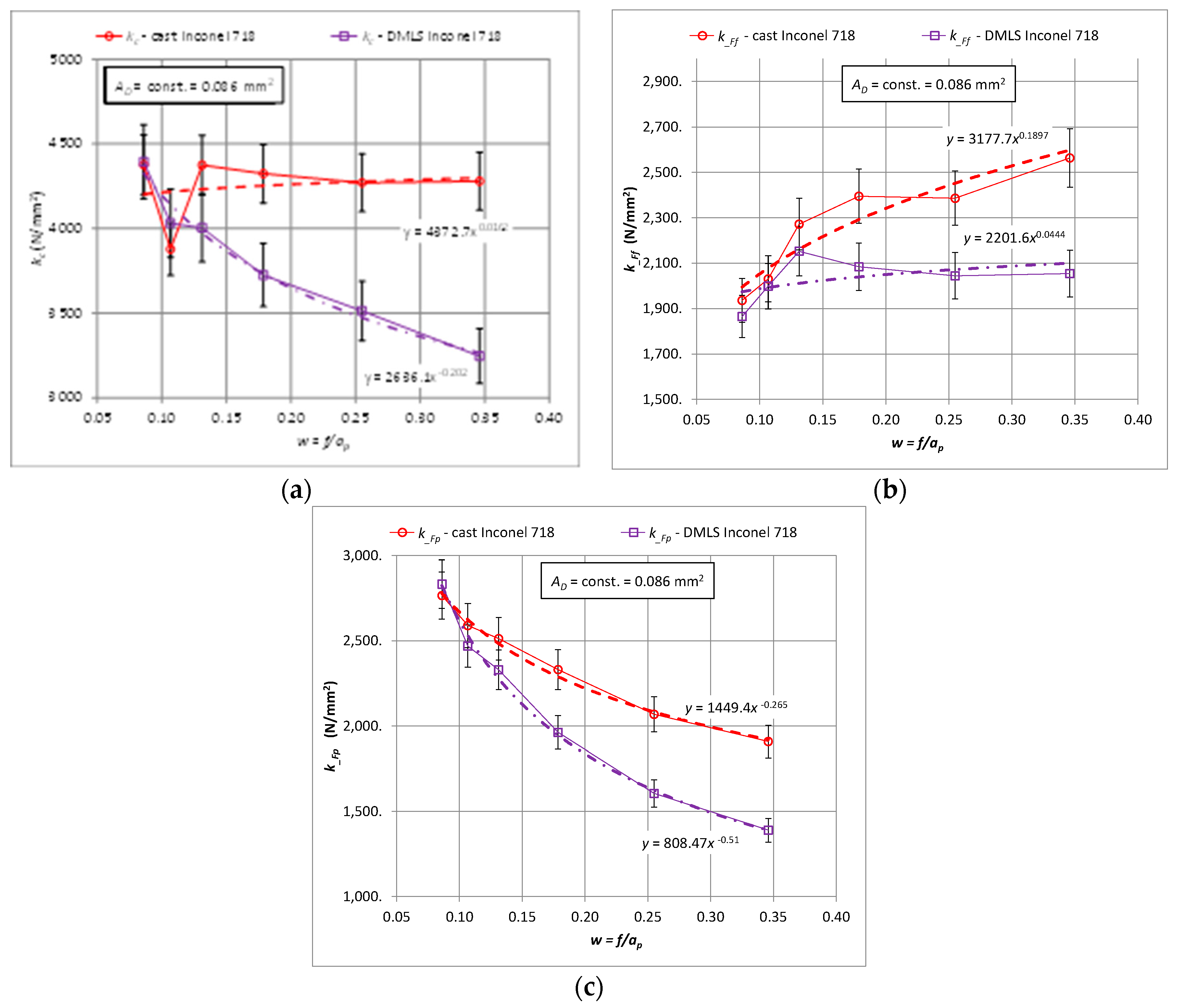
Studies have shown that for turning tapered surfaces, the specific cutting force kc values decrease with the increase in the cross-section of the cutting layer resulting from the change of the depth of cut ap.
The values of all components of the total cutting force for turning the material obtained by the additive method are lower than for turning the cast material. A progressive increase in value differences above the w > 0.15 parameter value was observed. The values of the Fc main cutting force for turning a cast alloy vary in the range of 0 to 32% in the analyzed cases. For w < 0.15, the values of the cutting forces when turning cast and laser sintered material are similar for all components.
The surface roughness Ra was lower in the machining of the laser sintered material than of the cast material. The surface roughness value Ra was within the range of 0.5–2.5 µm.
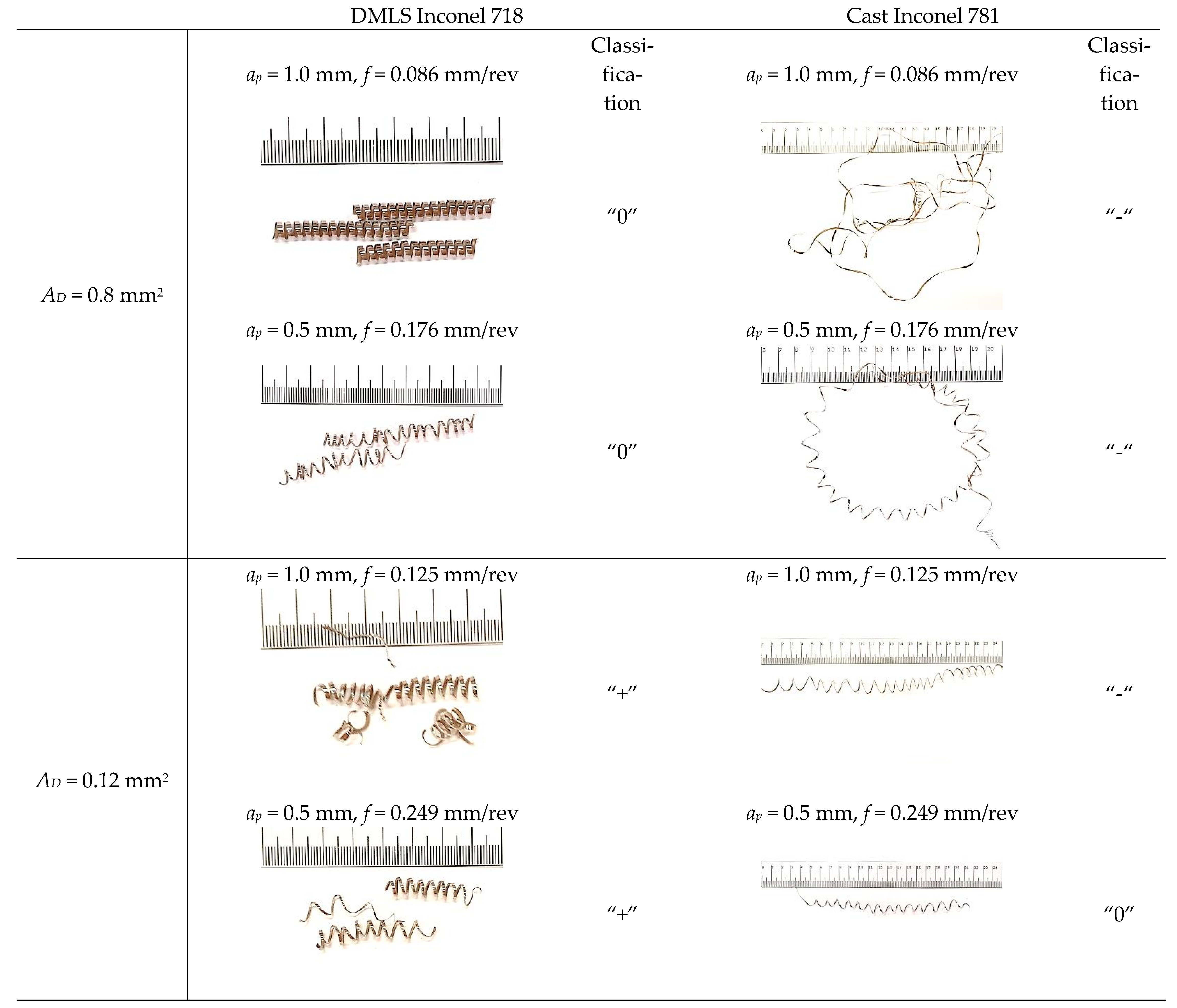
A slight influence of the shape of the cross-section of the cut layer on the chip shape was observed. The chip shape was significantly influenced by the value of the f feed.

Author Contributions

Conceptualization, K.L. and W.Z.; methodology, K.L.; software, G.S.; validation, K.L., W.Z. and G.S.; formal analysis, K.L.; investigation, K.L. and G.S.; data curation, K.L.; writing—original draft preparation, K.L. and G.S.; writing—review and editing, W.Z. and G.S.; visualization, G.S.; supervision, W.Z. All authors have read and agreed to the published version of the manuscript.

Funding

This research received no external funding.

Institutional Review Board Statement

Not applicable.

Informed Consent Statement

Not applicable.

Data Availability Statement

The data presented in this study are available on request from the corresponding author. The data are not publicly available due to privacy.

Conflicts of Interest

The authors declare that they have no conflict of interest.

References

  1. Chen, J.; Hu, Q.; Lv, X.; Li, X. Numerical simulation and experiment study on the nuclear fuel spacer grid stamping of Inconel 718. Procedia Eng. 2017, 207, 1534–1539. [Google Scholar] [CrossRef]
  2. Deng, D.; Peng, R.L.; Brodin, H.; Moverare, J. Microstructure and mechanical properties of Inconel 718 produced by selective laser melting: Sample orientation dependence and effects of post heat treatments. Mater. Sci. Eng. A 2018, 713, 294–306. [Google Scholar] [CrossRef]
  3. Thakur, D.G.; Ramamoorthy, B.; Vijayaraghavan, L. Study on the machinability characteristics of superalloy Inconel 718 during high speed turning. Mater. Des. 2009, 30, 1718–1725. [Google Scholar] [CrossRef]
  4. Hosseini, E.; Popovich, V. A review of mechanical properties of additively manufactured Inconel 718. Addit. Manuf. 2019, 30, 100877. [Google Scholar] [CrossRef]
  5. Ezugwu, E.O.; Wang, Z.M.; Machado, A.R. The machinability of nickel based alloys: A review. J. Mater. Process. Technol. 1999, 86, 1–16. [Google Scholar] [CrossRef]
  6. Anbarasan, N.; Gupta, B.K.; Prakash, S.; Muthukumar, P.; Oyyaravelu, R.; John Felix Kumar, R.; Jerome, S. Effect of heat treatment on the microstructure and mechanical properties of Inconel 718. Mater. Today Proc. 2018, 5, 7716–7724. [Google Scholar] [CrossRef]
  7. Caiazzo, F.; Alfieri, V.; Sergi, V.; Schipani, A.; Cinque, S. Dissimilar autogenous disk-laser welding of Haynes 188 and Inconel 718 superalloys for aerospace applications. Int. J. Adv. Manuf. Technol. 2013, 68, 1809–1820. [Google Scholar] [CrossRef]
  8. Grzesik, W.; Niesłony, P.; Habrat, W.; Sieniawski, J.; Laskowski, P. Investigation of tool wear in the turning of Inconel 718 superalloy in terms of process performance and productivity enhancement. Tribol. Int. 2018, 118, 337–346. [Google Scholar] [CrossRef]
  9. Huang, B.Y.; Wei, W.F.; Li, S.L.; Li, L.Y. Development of modern powder metallurgy materials and technology. Chin. J. Nonferrous Met. 2019, 29, 1917–1933. [Google Scholar]
  10. Huang, B.Y.; Yi, J.H. Current development of modern powder metallurgy materials and technologies. Shanghai Met. 2007, 3, 1–7. [Google Scholar]
  11. Guo, M.; Gu, D.; Xi, L.; Du, L.; Zhanga, H.; Zhanga, J. Formation of scanning tracks during Selective Laser Melting (SLM) of pure tungsten powder: Morphology, geometric features and forming mechanisms. Int. J. Refract. Met. Hard Mater. 2019, 79, 37–46. [Google Scholar] [CrossRef]
  12. Legutko, S. Additive techniques of manufacturing functional products from metal materials. IOP Conf. Ser. Mater. Sci. Eng. 2018, 393, 012003. [Google Scholar] [CrossRef]
  13. Bremen, S.; Meiners, W.; Diatlov, A. Selective Laser Melting. Laser Tech. J. 2012, 9, 33–38. [Google Scholar] [CrossRef]
  14. Strößner, J.; Terock, M.; Glatzel, U. Mechanical and Microstructural Investigation of Nickel-Based Superalloy IN718 Manufactured by Selective Laser Melting (SLM). Adv. Eng. Mater. 2015, 17, 1099–1105. [Google Scholar] [CrossRef]
  15. Trosch, T.; Strößner, J.; Völkl, R.; Glatzel, U. Microstructure and mechanical properties of selective laser melted Inconel 718 compared to forging and casting. Mater. Lett. 2016, 164, 428–431. [Google Scholar] [CrossRef]
  16. N’Dri, N.; Mindt, H.W.; Shula, B.; Megahed, M.; Peralta, A.; Kantzos, P.; Neumann, J. DMLS Process Modeling and Validation. In Proceedings of the TMS 2015 144th Annual Meeting & Exhibition, Orlando, FL, USA, 15–19 March 2015; pp. 389–396. [Google Scholar]
  17. Tucho, W.M.; Cuvillier, P.; Sjolyst-Kverneland, A.; Hansen, V. Microstructure and hardness studies of Inconel 718 manufactured by selective laser melting before and after solution heat treatment. Mater. Sci. Eng. A 2017, 689, 220–232. [Google Scholar] [CrossRef]
  18. Niaki, M.K.; Torabi, S.A.; Nonino, F. Why manufacturers adopt additive manufacturing technologies: The role of sustainability. J. Clean. Prod. 2019, 222, 381–392. [Google Scholar] [CrossRef]
  19. Chlebus, E.; Gruber, K.; Kuznicka, B.; Kurzac, J.; Kurzynowski, T. Effect of heat treatment on the microstructure and mechanical properties of Inconel 718 processed by selective laser melting. Mater. Sci. Eng. A. 2015, 639, 647–655. [Google Scholar] [CrossRef]
  20. Li, C.; Liu, Z.; Fang, X.; Guo, Y.B. Residual Stress in Metal Additive Manufacturing. Procedia CIRP 2018, 71, 348–353. [Google Scholar] [CrossRef]
  21. Liyong, M.; Ziyong, Z.; Bao, M.; Min, W. Effec of Pressure and Temperature on Densification in Electric Field—Assisted Sintering of Inconel 718 Superalloy. Materials 2021, 14, 2546. [Google Scholar]
  22. Thakur, A.; Gangopadhyay, S. State-of-the-art in surface integrity in machining of nickel-based superalloys. Int. J. Mach. Tools Manuf. 2016, 100, 25–54. [Google Scholar] [CrossRef]
  23. Madariaga, A.; Arrazola, P.J.; Esnaola, J.A.; Ruiz-Hervias, J.; Muñoz, P. Evolution of residual stresses induced by machining in a nickel based alloy under static loading at room temperature. Procedia CIRP 2014, 13, 175–180. [Google Scholar] [CrossRef] [Green Version]
  24. Madariaga, A.; Esnaola, J.A.; Arrazola, P.J.; Ruiz-Hervias, J.; Muñoz, P.; Ostolaza, K. Stability of machining induced residual stresses in Inconel 718 under quasi-static loading at room temperature. Mater. Sci. Eng. A. 2015, 620, 129–139. [Google Scholar] [CrossRef]
  25. Madariaga, A.; Esnaola, J.A.; Fernandez, E.; Arrazola, P.J.; Garay, A.; Morel, F. Analysis of residual stress and work-hardened profiles on Inconel 718 when face turning with large-nose radius tools. Int. J. Adv. Manuf. Technol. 2014, 71, 1587–1598. [Google Scholar] [CrossRef]
  26. Da Silva, F.A.V.; Denguir, L.A.; Outeiro, J.C. Residual stresses prediction in machining of Inconel 718 superalloy using a constitutive model considering the state of stress. Procedia CIRP 2020, 87, 527–532. [Google Scholar] [CrossRef]
  27. Hua, Y.; Liu, Z. Experimental Investigation of Principal Residual Stress and Fatigue Performance for Turned Nickel-Based Superalloy Inconel 718. Materials 2018, 11, 879. [Google Scholar] [CrossRef] [Green Version]
  28. Peng, H.; Tang, W.; Xing, Y.; Zhou, X. Semi-Empirical Prediction of Turned Surface Residual Stress for Inconel 718 Grounded in Experiments and Finite Element Simulations. Materials 2021, 14, 3937. [Google Scholar] [CrossRef]
  29. Hua, Y.; Liu, Z. Effects of cutting parameters and tool nose radius on surface roughness and work hardening during dry turning Inconel 718. Int. J. Adv. Manuf. Technol. 2018, 96, 2421–2430. [Google Scholar] [CrossRef]
  30. Struzikiewicz, G.; Zębala, W.; Słodki, B. Cutting parameters selection for sintered alloy AlSi10Mg longitudinal turning. Measurement 2019, 138, 39–53. [Google Scholar] [CrossRef]
  31. Wood, P.; Díaz-Álvarez, A.; Díaz-Álvarez, J.; Miguélez, M.H.; Rusinek, A.; Gunputh, U.F.; Williams, G.; Bahi, S.; Sienkiewicz, J.; Płatek, P. Machinability of INCONEL718 Alloy with a Porous Microstructure Produced by Laser Melting Powder Bed Fusion at Higher Energy. Materials 2020, 13, 5730. [Google Scholar] [CrossRef]
  32. Słodki, B.; Zębala, W.; Struzikiewicz, G. Correlation Between Cutting Data Selection and Chip Form in Stainless SteelTurning. Mach. Sci. Technol. 2015, 19, 217–235. [Google Scholar] [CrossRef]
Figure 1. A simplified diagram of the cross-section shapes of the cutting layer while maintaining a constant cross-section for turning with entering angle KR = 90°.
Materials 15 01448 g001
Figure 2. Characteristics of the components Fc, Ff, Fp (a) with specific cutting forces (b) and specific cutting force kc during the initial phase of cutting edge work (c) for turning the cone made of Inconel 718 alloy.
Materials 15 01448 g002
Figure 3. The characteristics of the components for turning with a constant cross-section of the machined layer AD = 0.8 mm2 for the printed and cast Inconel 718 alloy, (a) Fc component, (b) Ff component, (c) Fp component, (d) the ratio of the cutting forces Ff/Fc and Fp/Fc–cast material (e) the ratio of the cutting forces Ff/Fc and Fp/Fc–3D printed material.
Materials 15 01448 g003
Figure 4. Relationship of specific cutting force for the components Fc, Ff, Fp for turning with a constant cross-section of the cutting layer AD = 0.8 mm2 for the printed and cast Inconel 718 alloy, (a) kc, (b) k_Ff, (c) k_Fp.
Materials 15 01448 g004
Figure 5. The characteristic of the components for turning with a constant cross-section of the cutting layer AD = 1.2 mm2 for the printed Inconel 718 alloy, (a) Fc component, (b) Ff component, (c) Fp component.
Materials 15 01448 g005
Figure 6. Relationships for specific cutting force components Fc, Ff, Fp for turning with a constant cross-section of the cutting layer AD = 0.8 mm2 and AD = 1.2 mm2 for 3D printed Inconel 718, (a) kc, (b) k_Ff, (c) k_Fp.
Materials 15 01448 g006
Figure 7. Surface roughness Ra relationship for turning with a constant cross-section of the cutting layer AD = 0.08 mm2 and AD = 0.12 mm2 for 3D printed (a) and cast Inconel 718 alloy, (b) shape and profile-3D printed material, w = 0.18, (c) shape and profile-cast material, w = 0.18.
Materials 15 01448 g007
Figure 8. Chips’ photographs obtained for laser sintered and cast alloy turning.
Materials 15 01448 g008
Figure 9. Simplified algorithm of procedure (a) for minimizing the value of the actual cutting resistance and the schematic diagram of the method (b).
Materials 15 01448 g009
Figure 10. An example of the application of the algorithm for minimizing the value of specific cutting force when turning the Inconel 718 alloy using the DMLS method.
Materials 15 01448 g010
Table 1. Mechanical properties of the material Inconel 718 for DMLS and cast parts (at 20 °C).
MaterialTensile Strength (MPa)Yield Strength Δ(Rp 0.2%)HRCElongation at Break Δ(%)Density Δ(Cast Part) Δ(g/cm3)Density Δ(DMLS Part) Δ(g/cm3)
Inconel 718106078030278.28.15
Rockwell C (HRC) hardness measurement according to EN ISO 6508-1 on polished surface.
Table 2. Chemical composition of Inconel 718 (%).
NiCrNbMoTiAlCoCuSiCMn
50184.83.10.950.7<1.0<0.3<0.35<0.08<0.35
Publisher’s Note: MDPI stays neutral with regard to jurisdictional claims in published maps and institutional affiliations.

