
Hybridization Effects on Bending and Interlaminar Shear Strength of Composite Laminates


Abstract
1. Introduction
2. Materials and Methods
3. Results
4. Conclusions
- -
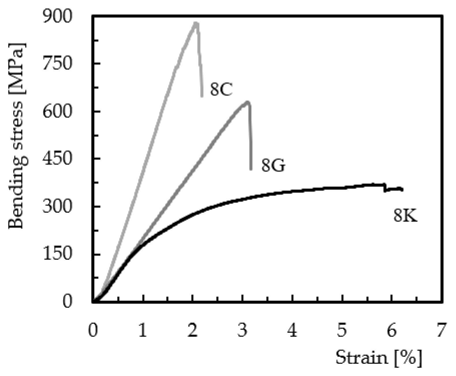
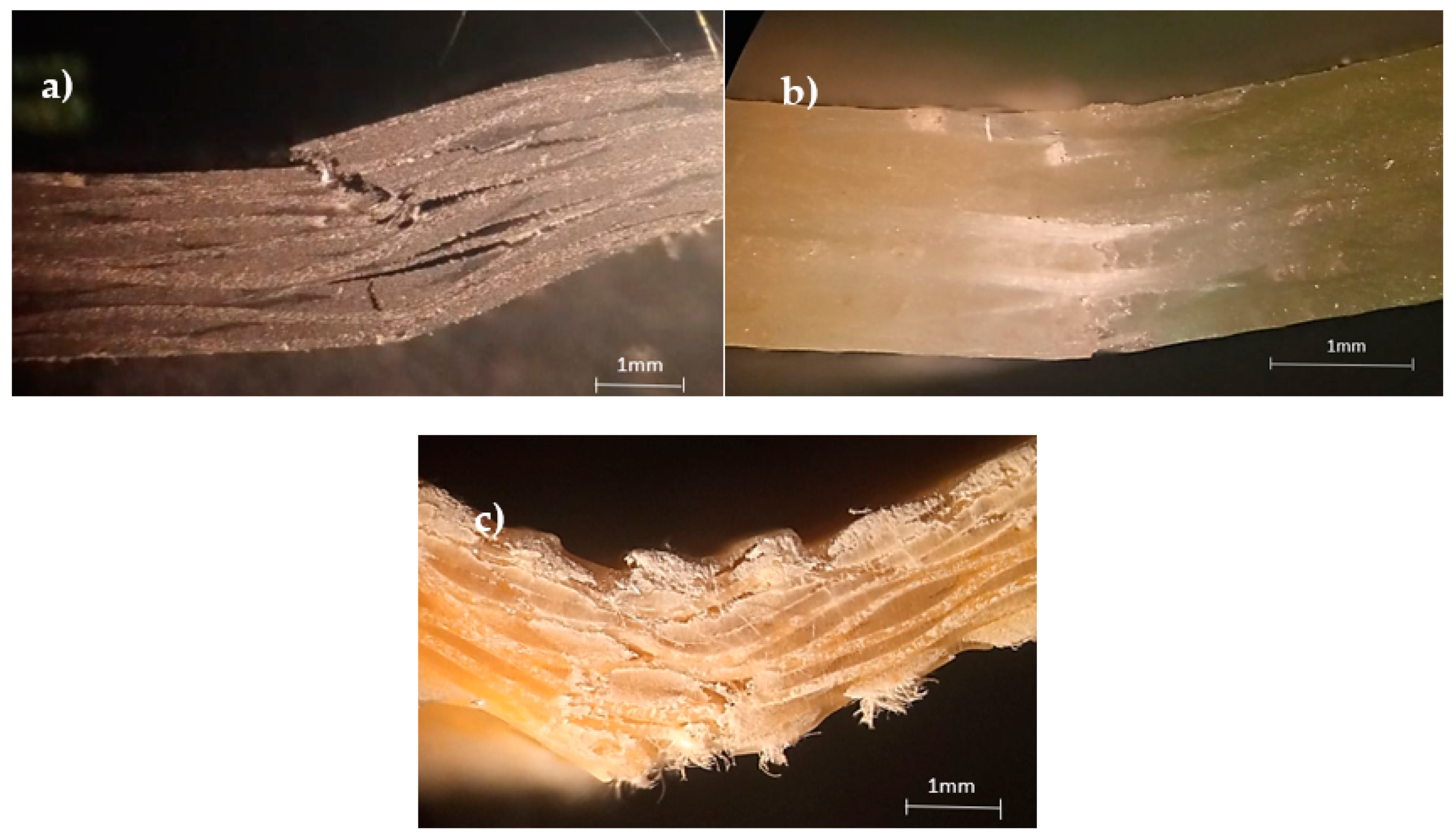
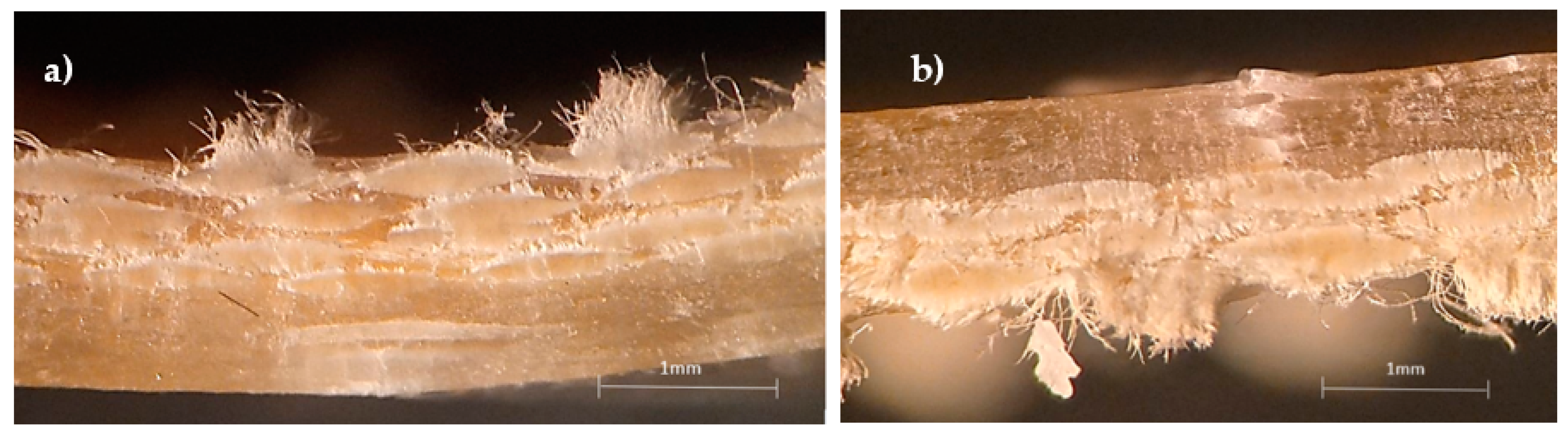
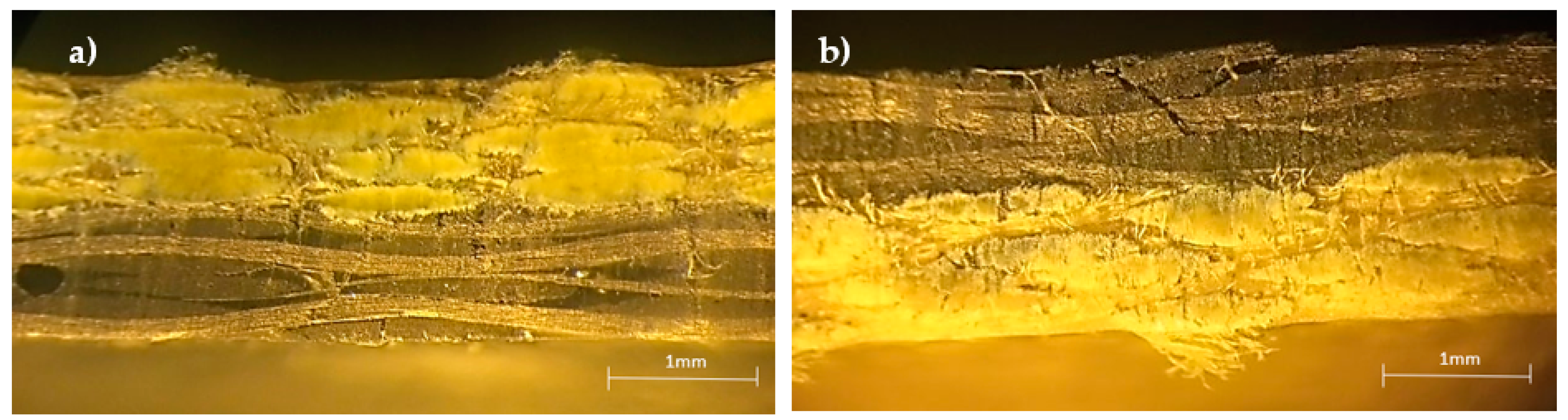
- for non-hybrid composites, the maximum bending stress and modulus were obtained for the carbon/epoxy composite, while the bending strain was the smallest. On the opposite side, the Kevlar/epoxy composite showed the lowest bending stress and modulus, while the bending strain had the highest value. These results were explained by the intrinsic properties of the composites’ constituents and by the damage mechanisms that proved to be very specific for each laminate. The interlaminar shear strength followed the same trend, with the highest ILSS value for the carbon/epoxy composite and the lowest for the Kevlar/epoxy composite;
- -
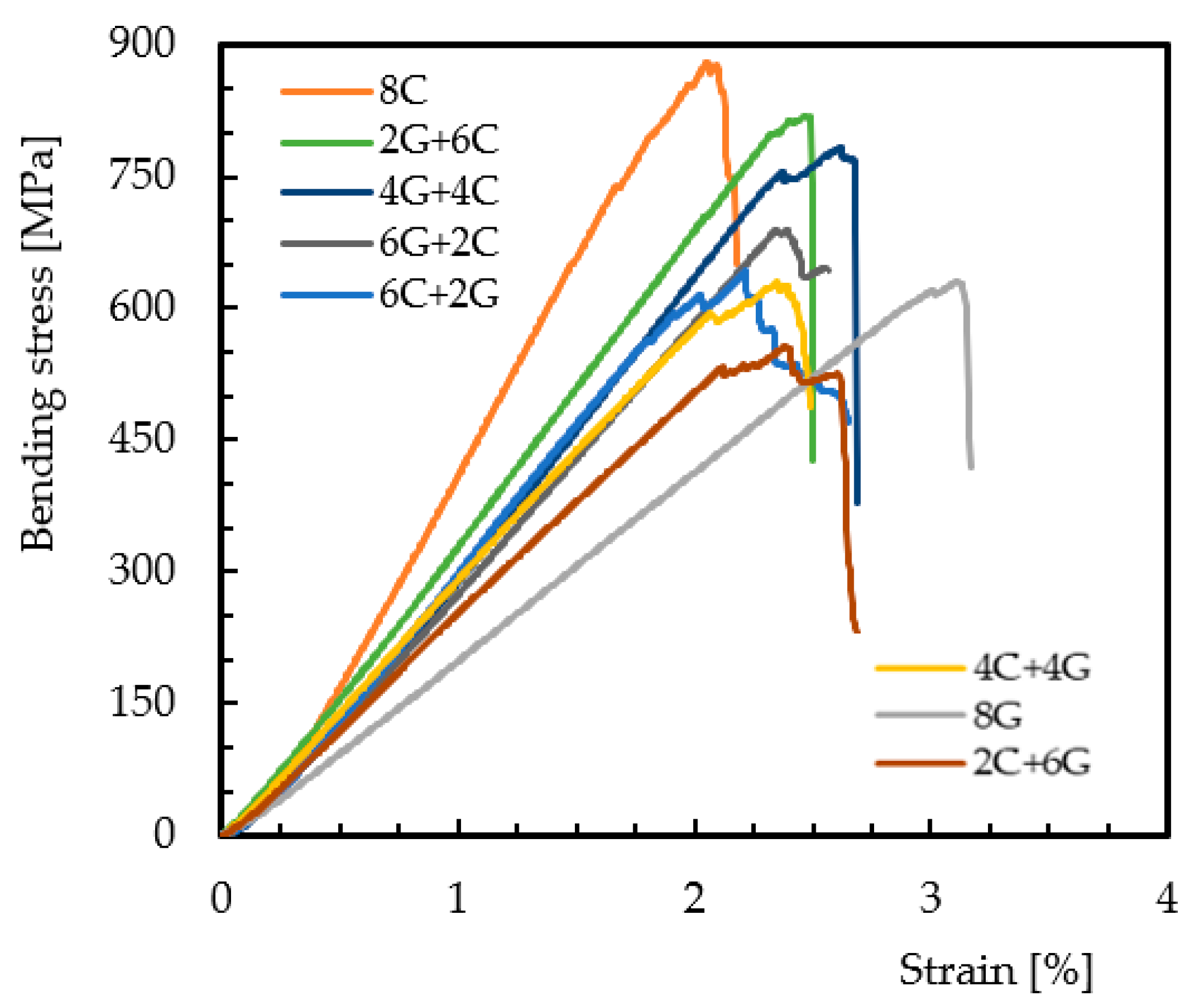
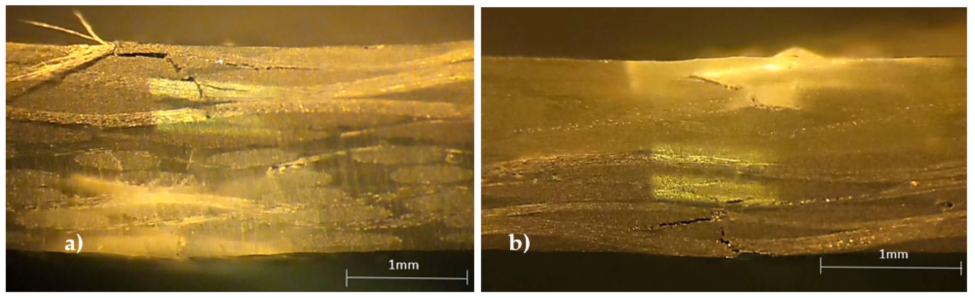
- about the hybridization effect, the highest values were obtained for composites involving carbon and glass fibers, with the latter placed on the compression side. This proves the poor compression performance of the carbon fibers. On the other hand, the results were very similar when Kevlar fibers were placed on the tensile side. Finally, the highest ILSS values were obtained for the composite involving carbon and glass fibers, while the lowest ILSS values were obtained for composites involving Kevlar fibers. Furthermore, it was observed that the fiber content and its positioning in the laminate affect both flexural strength and interlaminar shear strength, evidencing that these properties may be related.
Author Contributions
Funding
Institutional Review Board Statement
Informed Consent Statement
Data Availability Statement
Acknowledgments
Conflicts of Interest
References
- Durão, L.M.P.; Tavares, J.M.R.S.; de Albuquerque, V.H.C.; Marques, J.F.S.; Andrade, O.N.G. Drilling damage in composite material. Materials 2014, 7, 3802–3819. [Google Scholar] [CrossRef] [PubMed]
- Pasăre, M.M.; Luca, L.; Dimitrov, R.; Constantin, B. Aspects of composite materials evolution. Fiability Durab./Fiabil. Durabilitate 2019, 2, 55–60. [Google Scholar]
- Mallick, P.K. Fibre-Reinforced Composites Materials, Manufacturing and Design, 3rd ed.; Taylor & Francis Group: New York, NY, USA, 2007; p. 616. [Google Scholar]
- Chandrasekar, M.; Shahroze, R.M.; Ishak, M.R.; Saba, N.; Jawaid, M.; Senthilkumar, K.; Senthil Muthu Kumar, T.; Suchart Siengchin. Flax and sugar palm reinforced epoxy composites: Effect of hybridization on physical, mechanical, morphological and dynamic mechanical properties. Mater. Res. Express. 2019, 6, 105331. [Google Scholar] [CrossRef]
- Muhammad, N.; Jumahat, A.; Ali, N.M. Effect of hybridization on compressive properties of woven carbon, glass and kevlar hybrid composites. J. Teknol. 2015, 76, 75–80. [Google Scholar] [CrossRef]
- Makeev, A.; Ghaffari, S.; Seon, G. Improving compressive strength of high modulus carbon-fiber reinforced polymeric composites through fiber hybridization. Int. J. Eng. Sci. 2019, 142, 145–157. [Google Scholar] [CrossRef]
- Swolfs, Y.; Gorbatikh, L.; Verpoest, I. Fibre hybridisation in polymer composites: A review. Compos. Part A Appl. Sci. Manuf. 2014, 67, 181–200. [Google Scholar] [CrossRef]
- Gupta, M.K.; Srivastava, R.K. Mechanical Properties of Hybrid Fibers-Reinforced Polymer Composite: A Review. Polym. Plast. Technol. Eng. 2016, 55, 626–642. [Google Scholar] [CrossRef]
- Guo, R.; Xian, G.; Li, C.; Huang, X.; Xin, M. Effect of fiber hybridization types on the mechanical properties of carbon/glass fiber reinforced polymer composite rod. Mech. Adv. Mater. Struct. 2021, 9, 1–13. [Google Scholar] [CrossRef]
- Giancaspro, P.N.; Papakonstantinou, J.W.; Balaguru, C.G. Flexural Response of Inorganic Hybrid Composites With E-Glass and Carbon Fibers. J. Eng. Mater. Technol. 2010, 132, 021005. [Google Scholar] [CrossRef]
- Wonderly, C.E.; Grenestedt, J.; Fernlund, G. Comparison of mechanical properties of glass fiber/vinyl ester and carbon fiber/vinyl ester composites. Compos. Part B Eng. 2005, 36, 417–426. [Google Scholar] [CrossRef]
- Santos, P.; Valvez, S.; Monjon, A.; Reis, P.N.B. The hybridisation effect on the viscoelastic properties of polymeric composites. Procedia Struct. Integr. 2020, 28, 1816–1826. [Google Scholar] [CrossRef]
- Ghafaar, M.A.; Mazen, A.A.; El-Mahallawy, N.A. Behavior of Woven Fabric Reinforced Epoxy Composites Under Bending and Compressive Loads. JES J. Eng. Sci. 2006, 34, 453–469. [Google Scholar] [CrossRef]
- Madhavi, P.; Chandra Shekar, K.; Poojith, K.; Sai Kumar, P.; Usman Khan, P.; Leela Gowtham, P. Flexural and Inter-Laminar Shear Strength of Glass/Carbon Fabric Reinforced Composite. IOP Conf. Ser. Mater. Sci. Eng. 2021, 1057, 012016. [Google Scholar] [CrossRef]
- Sudarisman; MiguelIan, B.S.; Davies, I.J. The effect of partial substitution of E-glass fibre for carbon fibre on the mechanical properties of CFRP composites. In Proceedings of the International Conference on Materials and Metallurgical Technology, Surabaya, Indonesia, 24–25 June 2009; pp. 125–128. [Google Scholar]
- Dong, C.; Davies, I.J. Optimal design for the flexural behaviour of glass and carbon fibre reinforced polymer hybrid composites. J. Mater. 2012, 37, 450–457. [Google Scholar] [CrossRef]
- Oskouei, A.V.; Taleie, S.M. Experimental Investigation of Relaxation of Fiber-reinforced Polymer Composites. J. Reinf. Plast. Compos. 2010, 29, 2705–2712. [Google Scholar] [CrossRef]
- Ibarra, L.; Macias, A.; Palma, E. Stress-Strain and stress relaxation in oxidated short carbon fiber-thermoplastic elastomer composites. J. Appl. Polym. Sci. 1996, 61, 2447–2454. [Google Scholar] [CrossRef]
- Agarwal, B.D.; Broutman, L.J. Analysis and Performance of Fiber Composites, 2nd ed.; JohnWiley Sons Inc.: New York, NY, USA, 1990; p. 449. [Google Scholar]
- Donnet, B.; Bansal, R.C. Carbon Fibers, 3rd ed.; Marcel Dekker Inc.: New York, NY, USA, 1998; p. 567. [Google Scholar]
- Harris, B. Engineering Composite Materials, 1st ed.; The Institute of Materials: London, UK, 1999; p. 194. [Google Scholar]
- Turla, P.; Kumar, S.S.; Reddy, P.H.K.; Shekar, C. Interlaminar Shear Strength of Carbon Fiber and Glass Fiber Reinforced Epoxy Matrix Hybrid Composite. Int. J. Res. Eng. Adv. Technol. 2014, 2, 1–4. [Google Scholar]
- Padmanabhan, K.; Kishore, J. Interlaminar shear of woven fabric Kevlar-epoxy composites in three-point loading. Mater. Sci. Eng. A. 1995, 197, 113–118. [Google Scholar] [CrossRef]
- Reis, P.N.B.; Gorbatikh, L.; Ivens, J.; Lomov, S.V. Strain-Rate Sensitivity and Stress Relaxation of Hybrid Self-Reinforced Polypropylene Composites under Bending Loads. Compos. Struct. 2019, 209, 802–810. [Google Scholar] [CrossRef]
- Ferreira, J.A.M.; Reis, P.N.B.; Costa, J.D.M.; Richardson, M.O.W. Fatigue behavior of Kevlar composites with nanoclay filled epoxy resin. J. Compos. Mater. 2013, 47, 1885–1895. [Google Scholar] [CrossRef]
- Allred, R.E.; Hall, N.H. Volume Fraction Determination of Kevlar 49/Epoxy Composites. Polym. Eng. Sci. 1979, 19, 907–909. [Google Scholar] [CrossRef]
- Peters, S.T. Handbook of Composites, 2nd ed.; Chapman & Hall: London, UK, 1998; p. 1118. [Google Scholar]
- Chung, D.D.L. Composite Materials, 2nd ed.; Springer: London, UK, 2010; p. 349. [Google Scholar]
- Reis, P.; Ferreira, J.; Antunes, F.; Costa, J. Fatigue Notch Sensibility of Thermoplastic Glass Fibres Composites. Mater. Sci. Forum. 2006, 514–516, 653–656. [Google Scholar] [CrossRef]
- Amaro, A.P.B.M.; Reis, P.; Moura, M.F.S.F. Residual Strength after Low Velocity Impact in Carbon-Epoxy Laminates. Mater. Sci. Forum. 2006, 514–516, 624–628. [Google Scholar] [CrossRef]
- Amaro, D.A.M.; Reis, P.N.B.; Neto, M.A.; Cirne, J.M. Residual impact strength of carbon/epoxy laminates after flexural loadings. Compos. Struct. 2016, 146, 69–74. [Google Scholar] [CrossRef]
- Reis, P.; Ferreira, J.; Antunes, F.; Costa, J. Flexural behaviour of hybrid laminated composites. Compos. Part A-Appl. S. 2007, 38, 1612–1620. [Google Scholar] [CrossRef]
- Amaro, A.; Reis, P.N.B.; de Moura, M.F.S.F. Delamination effect on bending behaviour in carbon-epoxy composites. Strain 2011, 47, 203–208. [Google Scholar] [CrossRef]
- Zhang, J.; Chaisombat, K.; He, S.; Wang, C.H. Hybrid composite laminates reinforced with glass/carbon woven fabrics for lightweight load bearing structures. Mater. Des. 2012, 36, 75–80. [Google Scholar] [CrossRef]
- Bekyarova, E.I.; Thostenson, E.; Yu, A.; Kim, H.; Gao, J.; Tang, J.; Al, E. Multiscale carbon nanotube-carbon fiber reinforcement for advance epoxy composites. Langmuir 2007, 23, 3940–3974. [Google Scholar] [CrossRef]
- Adhikari, K.; Hubert, P.; Benoit, S.; Andrew, J. Effect of the Localized Application of SWNT Modified Epoxy on the Interlaminar Shear Strength of Carbon Fibre Laminates. In Proceedings of the 47th AIAA/ASME/ASCE/AHS/ASC Structures, Structural Dynamics, and Materials, Newport, Rhode Island, 1–4 May 2006; p. 10. [Google Scholar]
- Mouritz, A.P.; Gallagher, J.; Goodwin, A.A. Flexural strength and interlaminar shear strength of stitched GRP laminates following repeated impacts. Compos. Sci. Technol. 1997, 57, 509–522. [Google Scholar] [CrossRef]
- Alsaadi, M.; Ugla, A.A.; Erklig, A. A comparative study on the interlaminar shear strength of carbon, glass, and Kevlar fabric/epoxy laminates filled with SiC particles. J. Compos. Mater. 2017, 51, 2835–2844. [Google Scholar] [CrossRef]
- Wu, Z.; Li, J.; Huang, C.; Li, L. Effect of matrix modification on interlaminar shear strength of glass fibre reinforced epoxy composites at cryogenic temperature. Phys. Procedia. 2015, 67, 1068–1073. [Google Scholar] [CrossRef][Green Version]
- Gao, J.; Wang, X.; Huang, J.; Yao, J.; Yang, J.; Liu, X. Effects of different fluorination routes on aramid fiber surface structures and interlaminar shear strength of its composites. Appl. Surf. Sci. 2013, 270, 627–633. [Google Scholar] [CrossRef]
- Wu, J.; Cheng, X. Study of interlaminar shear strength of rare earths treated aramid fiber reinforced epoxy composites. J. Mater. Sci. 2005, 40, 1043–1045. [Google Scholar] [CrossRef]
- Kim, Y.; Mai, J. High strength, high fracture toughness fibre composites with interface control-a review. Compos. Sci. Technol. 1991, 41, 333–378. [Google Scholar] [CrossRef]
- Khan, S.U.; Kim, J.K. Improved interlaminar shear properties of multiscale carbon fiber composites with bucky paper interleaves made from carbon nanofibers. Carbon 2012, 50, 5265–5277. [Google Scholar] [CrossRef]
- Kim, J.; Mai, Y. Engineered Interfaces in Fiber Reinforced Composites, 1st ed.; Elsevier Science Ltd.: Oxford, UK, 1998; p. 391. [Google Scholar]
- Almeida, J.H.S.; Angrizani, C.C.; Botelho, E.C.; Amico, S.C. Effect of fiber orientation on the shear behavior of glass fiber/epoxy composites. Mater. Des. 2015, 65, 789–795. [Google Scholar] [CrossRef]
- Abali, F.; Pora, A.; Shivakumar, K. Modified short beam shear test for measurement of interlaminar shear strength of composites. J. Compos. Mater. 2003, 37, 453–464. [Google Scholar] [CrossRef]


| Group 1 | Average Thickness [mm] | Group 2 | Average Thickness [mm] | Group 3 | Average Thickness [mm] |
|---|---|---|---|---|---|
| 8C | 1.8 | 8G | 1.5 | 8K | 1.9 |
| 2C + 6G | 1.6 | 2G + 6K | 1.8 | 2K + 6C | 1.8 |
| 4G + 4C | 1.7 | 4G + 4K | 1.7 | 4K + 4C | 1.9 |
| 6C + 2G | 1.7 | 6G + 2K | 1.6 | 6K + 2C | 1.9 |
| Laminates | Fiber Content (wt.%) | ||
|---|---|---|---|
| Carbon Fibers | Glass Fibers | Kevlar Fibers | |
| 8C | 60 ± 0.23 | - | - |
| 2C + 6G | 15 ± 0.19 | 49 ± 0.18 | - |
| 4C + 4G | 30 ± 0.16 | 32 ± 0.79 | - |
| 6C + 2G | 43 ± 0.26 | 17 ± 0.28 | - |
| 8G | - | 63 ± 0.19 | - |
| 2G + 6K | - | 17 ± 0.97 | 41 ± 0.22 |
| 4G + 4K | - | 32 ± 0.48 | 28 ± 0.36 |
| 6G + 2K | - | 49 ± 0.25 | 13 ± 0.14 |
| 8K | - | - | 56 ± 0.2 |
| 2K + 6C | 43 ± 0.58 | - | 13 ± 0.17 |
| 4K + 4C | 30 ± 0.25 | - | 28 ± 0.25 |
| 6K + 2C | 15 ± 0.22 | - | 41 ± 0.19 |
| Laminates | σf [MPa] | Ef [GPa] | E |
|---|---|---|---|
| 8C | 843.3 ± 33.2 | 48.4 ± 0.9 | 2.0 ± 0.06 |
| 2G + 6C | 820.0 ± 35.0 | 38.8 ± 0.6 | 2.5 ± 0.10 |
| 4G + 4C | 785.2 ± 20.5 | 34.8 ± 1.9 | 2.6 ± 0.08 |
| 6G + 2C | 694.6 ± 16.8 | 30.7 ± 1.6 | 2.4 ± 0.07 |
| 6C + 2G | 652.9 ± 27.6 | 37.4 ± 4.4 | 2.2 ± 0.10 |
| 4C + 4G | 637.2 ± 12.8 | 31.0 ± 2.8 | 2.4 ± 0.09 |
| 2C + 6G | 596.1 ± 25.1 | 27.7 ± 2.8 | 2.5 ± 0.08 |
| 8G | 632.5 ± 11.8 | 22.1 ± 0.7 | 3.3 ± 0.09 |
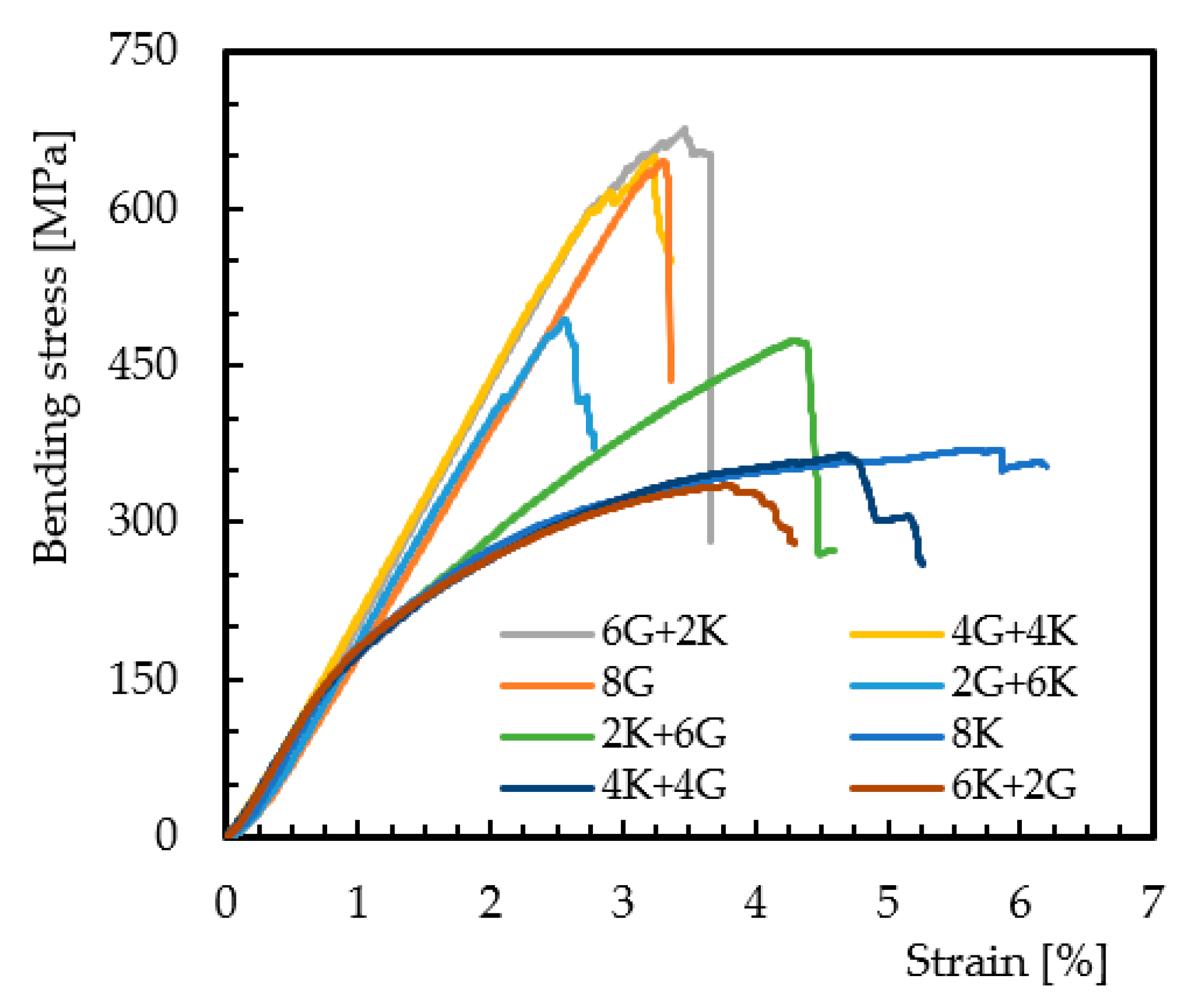
| Laminates | σf [MPa] | Ef [GPa] | εf [%] |
|---|---|---|---|
| 8G | 632.5 ± 11.8 | 22.1 ± 0.7 | 3.3 ± 0.09 |
| 2K + 6G | 465.4 ± 16.0 | 19.0 ± 0.9 | 4.4 ± 0.08 |
| 4K + 4G | 354.1 ± 13.1 | 19.9 ± 1.5 | 4.6 ± 0.30 |
| 6K + 2G | 332.3 ± 7.0 | 20.5 ± 2.2 | 4.0 ± 0.13 |
| 6G + 2K | 696.5 ± 41.2 | 23.3 ± 1.5 | 3.4 ± 0.10 |
| 4G + 4K | 646.8 ± 20.3 | 23.2 ± 1.4 | 3.2 ± 0.16 |
| 2G + 6K | 500.6 ± 14.0 | 23.9 ± 1.8 | 2.4 ± 0.22 |
| 8K | 378.2 ± 8.8 | 21.0 ± 1.3 | 6.2 ± 0.46 |
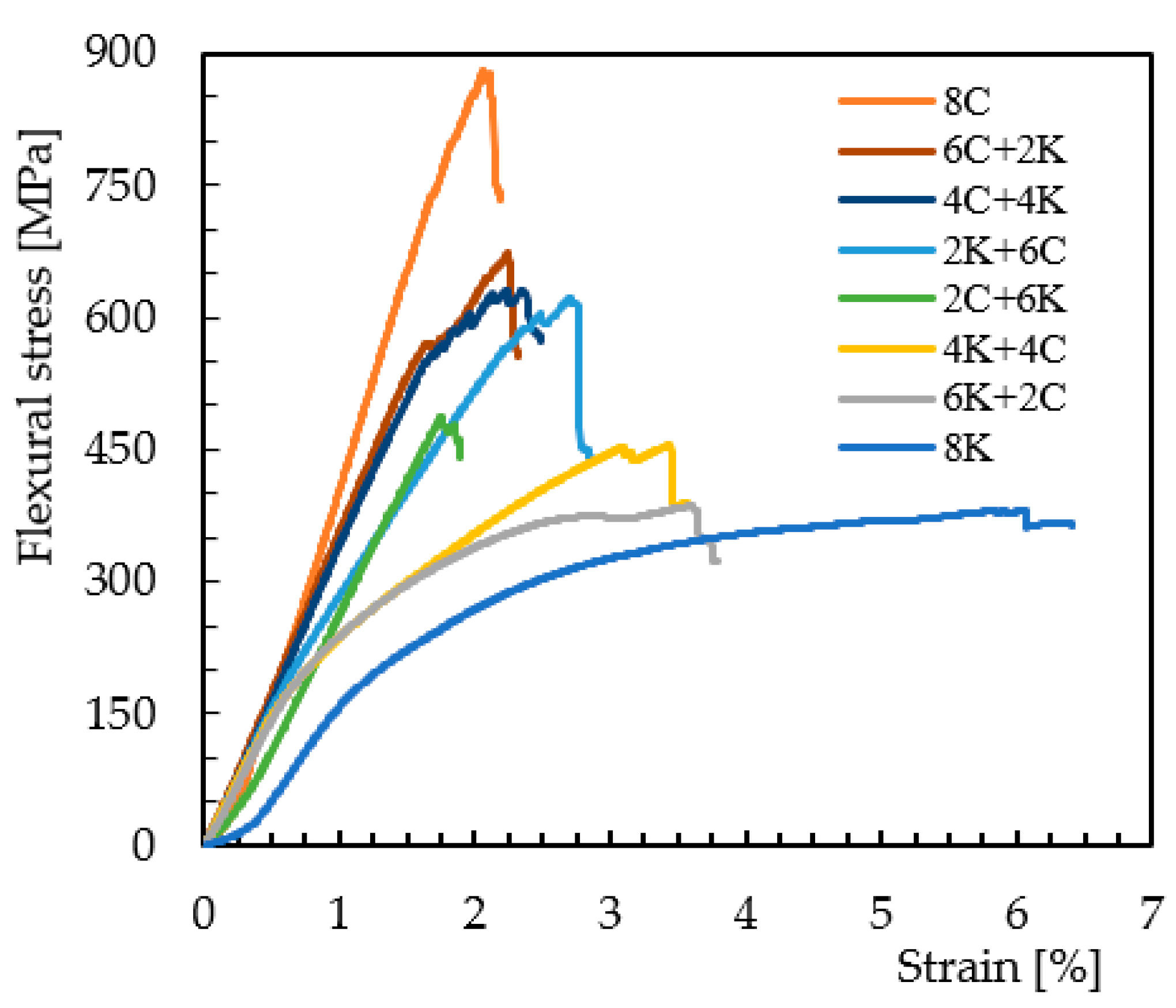
| Laminates | σf [MPa] | Ef [GPa] | εf [%] |
|---|---|---|---|
| 8C | 843.3 ± 33.2 | 48.4 ± 0.9 | 2.0 ± 0.06 |
| 2K + 6C | 629.4 ± 32.2 | 24.2 ± 1.8 | 2.6 ± 0.19 |
| 4K + 4C | 471.4 ± 18.3 | 25.6 ± 1.8 | 3.4 ± 0.18 |
| 6K + 2C | 399.0 ± 20.1 | 29.1 ± 3.5 | 3.8 ± 0.30 |
| 6C + 2K | 644.6 ± 32.0 | 42.5 ± 6.0 | 2.0 ± 0.20 |
| 4C + 4K | 638.7 ± 19.0 | 34.5 ± 2.4 | 2.0 ± 0.09 |
| 2C + 6K | 488.8 ± 34.7 | 29.9 ± 2.9 | 1.8 ± 0.06 |
| 8K | 378.2 ± 8.8 | 21.0 ± 1.3 | 6.2 ± 0.46 |
| Laminates | ILSS [MPa] | Decrease in Relation to 8C [%] |
|---|---|---|
| 8C | 53.6 ± 1.3 | - |
| 8G | 46.8 ± 2.2 | −12.7% |
| 8K | 28.6 ± 1.1 | −46.6% |
| Laminates | ILSS [MPa] | Decrease in Relation to 8C [%] |
|---|---|---|
| 8C | 53.6 ± 1.29 | - |
| 2G + 6C | 46.7 ± 0.96 | −12.9% |
| 4G + 4C | 51.1 ± 0.58 | −4.7% |
| 6G + 2C | 45.3 ± 2.10 | −15.5% |
| 6C + 2G | 45.6 ± 1.04 | −14.9% |
| 4C + 4G | 48.9 ± 1.98 | −8.8% |
| 2C + 6G | 39.6 ± 2.91 | −26.1% |
| 8G | 46.8 ± 2.15 | −12.7% |
| Laminates | ILSS [MPa] | Decrease in Relation to 8G [%] |
|---|---|---|
| 8G | 46.8 ± 2.15 | - |
| 2K + 6G | 34.5 ± 4.05 | −26.3% |
| 4K + 4G | 30.8 ± 2.22 | −34.2% |
| 6K + 2G | 33.2 ± 3.21 | −29.1% |
| 6G + 2K | 37.6 ± 1.15 | −19.7% |
| 4G + 4K | 34.4 ± 0.81 | −26.5% |
| 2G + 6K | 32.5 ± 0.98 | −30.6% |
| 8K | 28.6 ± 1.09 | −38.9% |
| Laminates | ILSS [MPa] | Decrease in Relation to 8C [%] |
|---|---|---|
| 8C | 53.6 ± 1.29 | - |
| 2K + 6C | 44.8 ± 0.58 | −16.4% |
| 4K + 4C | 34.5 ± 1.57 | −35.6% |
| 6K + 2C | 31.9 ± 0.7 | −40.5% |
| 6C + 2K | 42.5 ± 1.53 | −20.7% |
| 4C + 4K | 37.0 ± 1.69 | −31.0% |
| 2C + 6K | 36.2 ± 0.82 | −32.5% |
| 8K | 28.6 ± 1.09 | −46.6% |
Publisher’s Note: MDPI stays neutral with regard to jurisdictional claims in published maps and institutional affiliations. |
© 2022 by the authors. Licensee MDPI, Basel, Switzerland. This article is an open access article distributed under the terms and conditions of the Creative Commons Attribution (CC BY) license (https://creativecommons.org/licenses/by/4.0/).
Share and Cite
Monjon, A.; Santos, P.; Valvez, S.; Reis, P.N.B. Hybridization Effects on Bending and Interlaminar Shear Strength of Composite Laminates. Materials 2022, 15, 1302. https://doi.org/10.3390/ma15041302
Monjon A, Santos P, Valvez S, Reis PNB. Hybridization Effects on Bending and Interlaminar Shear Strength of Composite Laminates. Materials. 2022; 15(4):1302. https://doi.org/10.3390/ma15041302
Chicago/Turabian StyleMonjon, Alice, Paulo Santos, Sara Valvez, and Paulo N. B. Reis. 2022. "Hybridization Effects on Bending and Interlaminar Shear Strength of Composite Laminates" Materials 15, no. 4: 1302. https://doi.org/10.3390/ma15041302
APA StyleMonjon, A., Santos, P., Valvez, S., & Reis, P. N. B. (2022). Hybridization Effects on Bending and Interlaminar Shear Strength of Composite Laminates. Materials, 15(4), 1302. https://doi.org/10.3390/ma15041302