
Corrosion Resistance of MgO and Cr2O3-Based Refractory Raw Materials to PbO-Rich Cu Slag Determined by Hot-Stage Microscopy and Pellet Corrosion Test

 ,
,  , , ,
, , , 
Abstract
:1. Introduction
2. Materials and Methods
2.1. Characterization of Refractory Raw Materials and Cu Slag
2.2. Corrosion Tests of Raw Material–Slag Mixtures
2.2.1. Hot-Stage Microscopy
2.2.2. Pellet Test
3. Results
3.1. Characterization of Raw Materials
3.1.1. Chemical Composition of Raw Materials by XRF
3.1.2. The Phase Composition of Raw Materials by XRD
3.2. Characterization of Cu Slag
3.2.1. Chemical Composition of Cu Slag by XRF
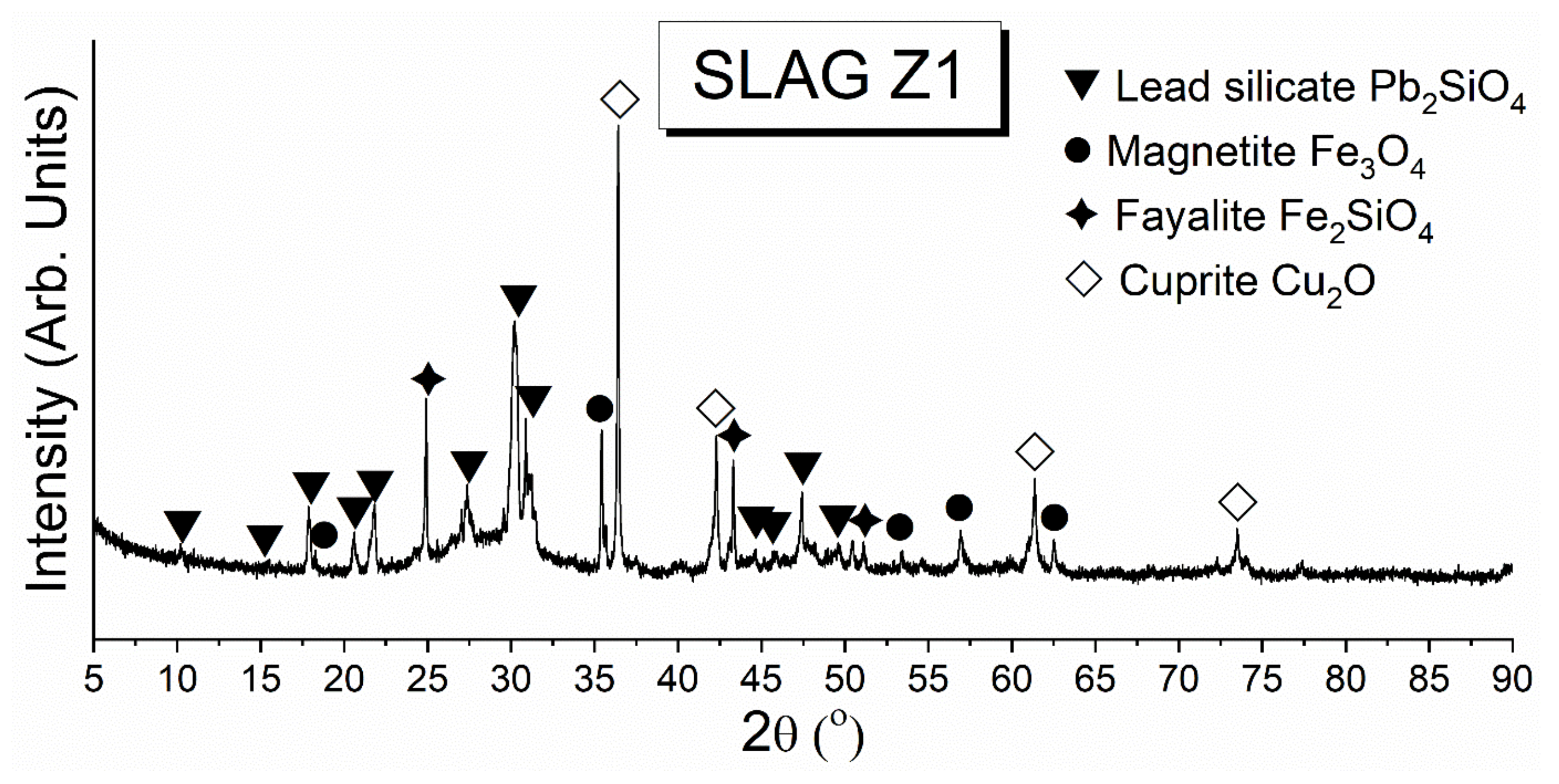
3.2.2. The Phase Composition of Cu Slag by XRD
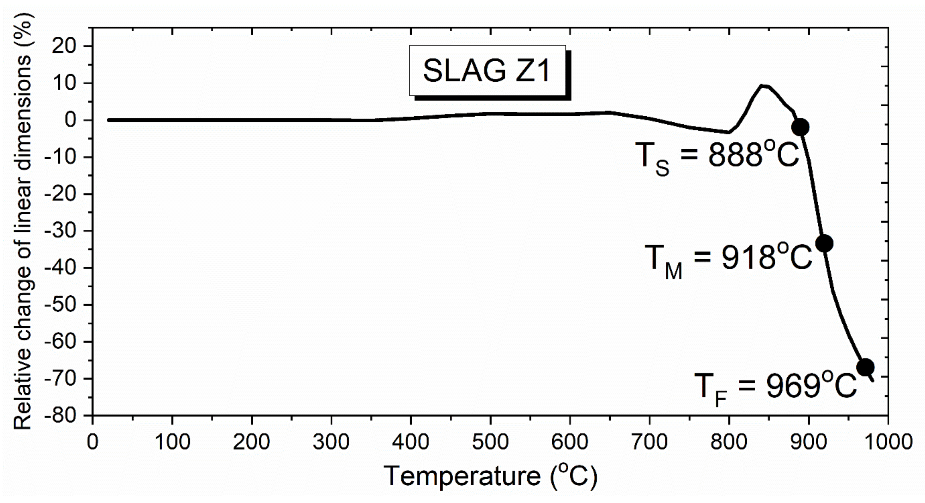
3.2.3. Hot-Stage Microscopy Test of Cu Slag
3.3. Corrosion of Raw Material–Cu Slag Mixtures
3.3.1. Hot-Stage Microscopy Test
3.3.2. Pellet Test
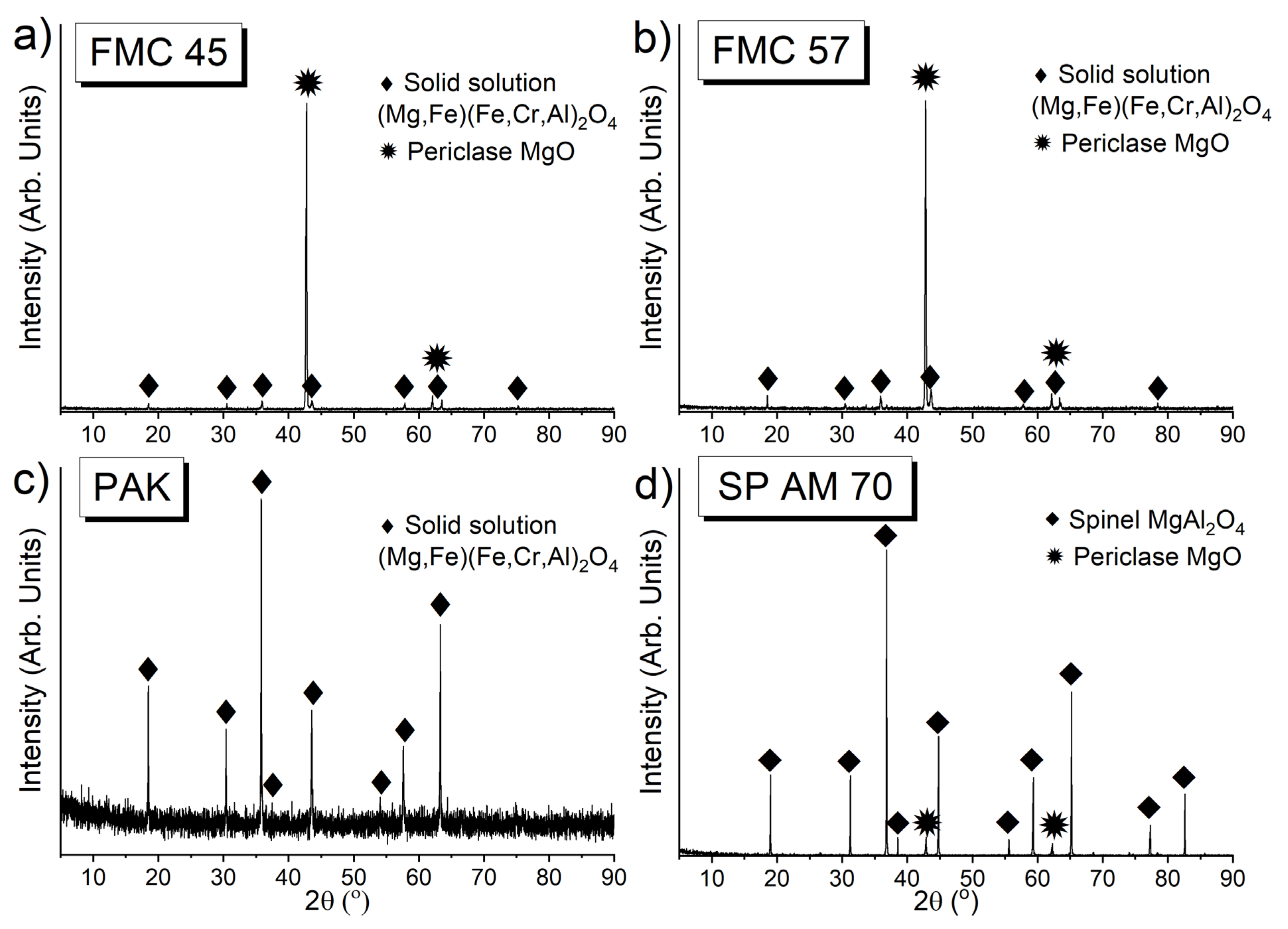
Phase Composition of the Raw Material–Slag Mixtures after the Pellet Test
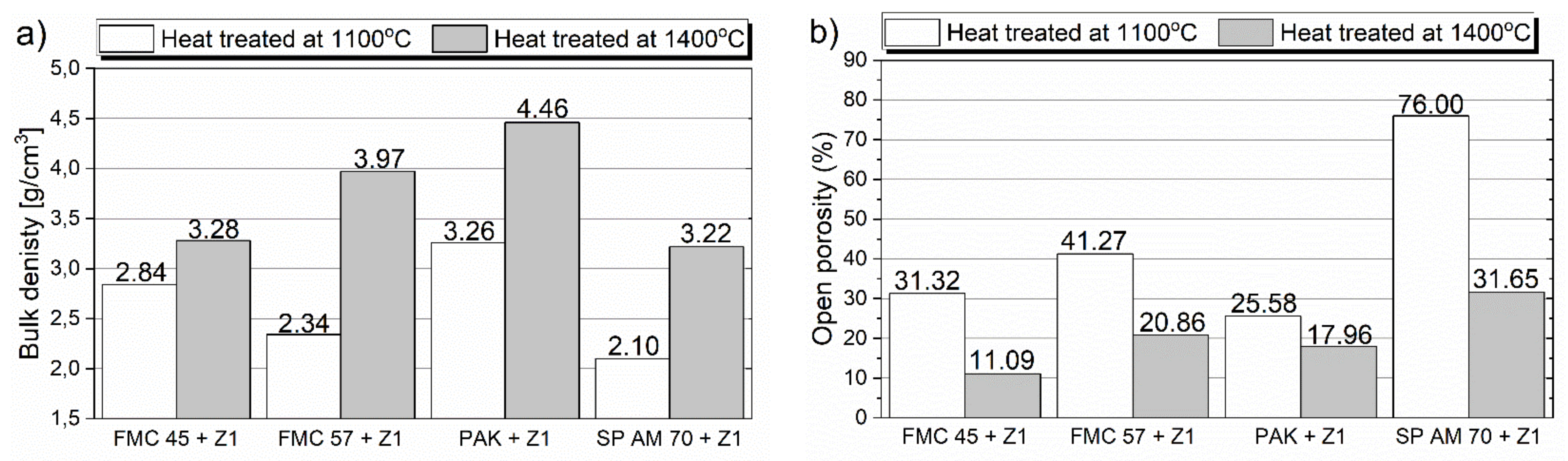
Bulk Density and Open Porosity of the Raw Material–Slag Mixtures after Pellet Test
Microstructure Analysis of the Raw Material–Slag Mixtures after the Pellet Test
4. Discussion

| Research Work | Testing Materials and Conditions | Massive Formation of Forsterite | Dissolution of Mg into Melt | Diffusion of Fe and Cu into MgO Grains | Diffusion of Fe into Chromite Grains | Formation of Güggenite in Contact with Cr-Containing Material | Formation of Güggenite in Contact with Cr-Free Material | Formation of Corrosion Protective/Interface Layer |
|---|---|---|---|---|---|---|---|---|
| Present work | Raw materials: FMC 45, FMC 57, PAK, SP AM 70 Corrosive agent: PbO-rich copper slag Temperature: 1100 °C and 1400 °C | + | + | + | + | + | + | |
| [42] | Product: MgO-Cr Corrosive agent: PbO-rich copper slags Temperature: 1300 °C | + | + | + | + | + | ||
| [40] | Product: MgO-Cr Corrosive agent: PbO-based slag Temperature: 1300 °C | + | + | + | + | |||
| [39] | Product: MgO-Cr Corrosive agent: PbO-SiO2-MgO slag Temperature: 1200 °C | + | + | + | ||||
| [2] | Product: MgO-Cr Corrosive agent: Cu-CuxO-PbO Temperature: 1200 °C | + | + | + | ||||
| [25] | Product: MgO-Cr Corrosive agent: Fayalite slag with increased ZnO content Temperature: 1200 °C | + | + | + | ||||
| [74] | Product: MgO-Cr Corrosive agent: Copper smelting slag Temperature: 1250 °C | + | + | + | + | + | ||
| [29] | Product: Al2O3-Cr Corrosive agent: Fayalite slag with increased ZnO content Temperature: 1200 °C | Dissolution of Al in slag | + | + | ||||
| [30] | Product: MgAl2O4 Corrosive agent: Cu2OT emperature: 1300 °C | + | ||||||
| [36] | Product: MgO doped with ZrO2 nanoparticles Corrosive agent: Fayalite slag Temperature: 1450 °C | + | + |
5. Conclusions
- Four commercial refractory raw materials commonly used in refractories for Cu metallurgy—two magnesia–chromite co-clinkers (FMC 45 and FMC 57), a chromite ore (PAK), and a fused spinel (SP AM 70)—were comparatively investigated against PbO-rich Cu slag by hot-stage microscopy and pellet corrosion test.
- Test slag, containing the high levels of PbO of 39% and CuOx of 16%, was characterized by a low melting point of 969 °C, determined by hot-stage microscopy test.
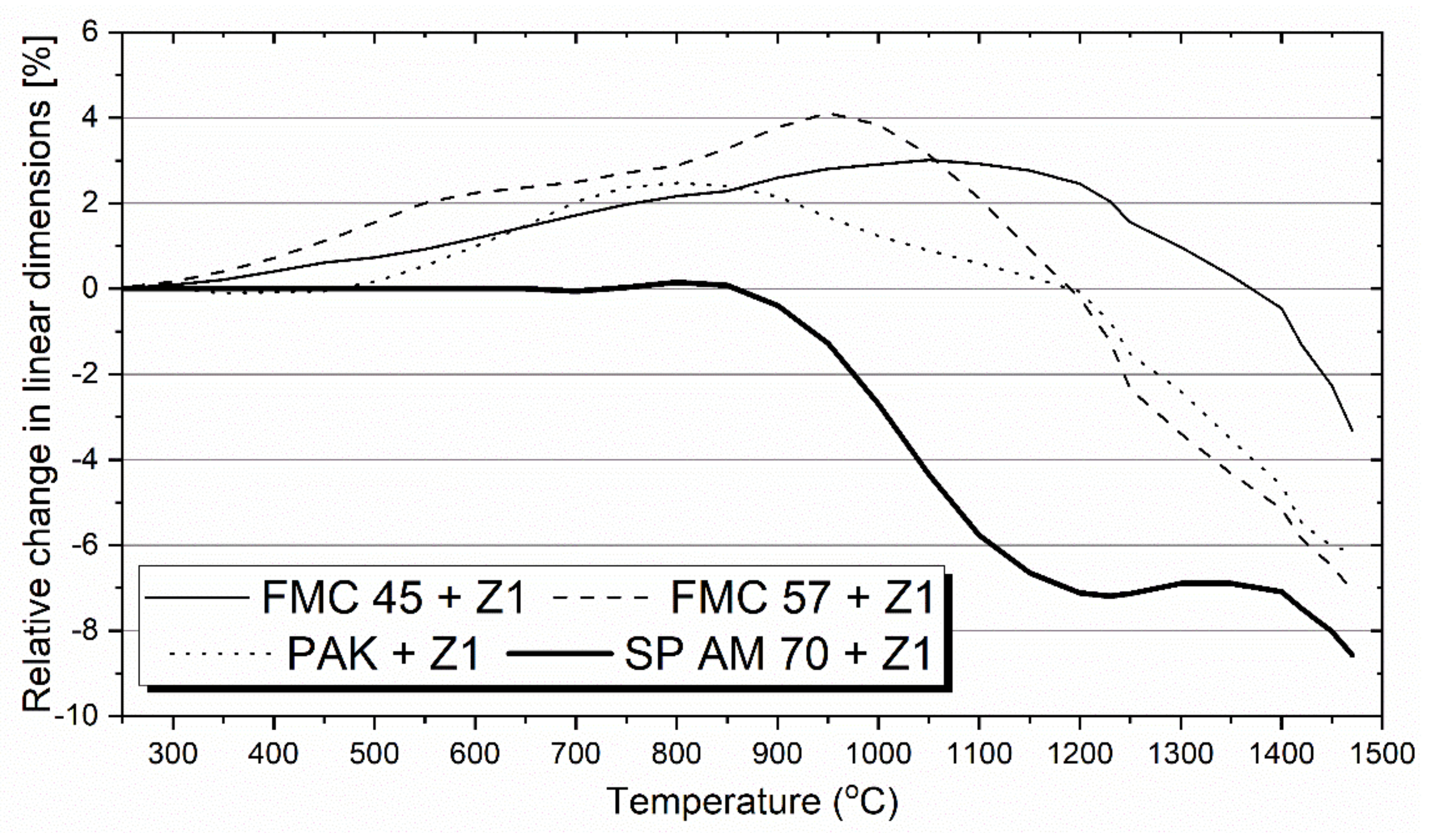
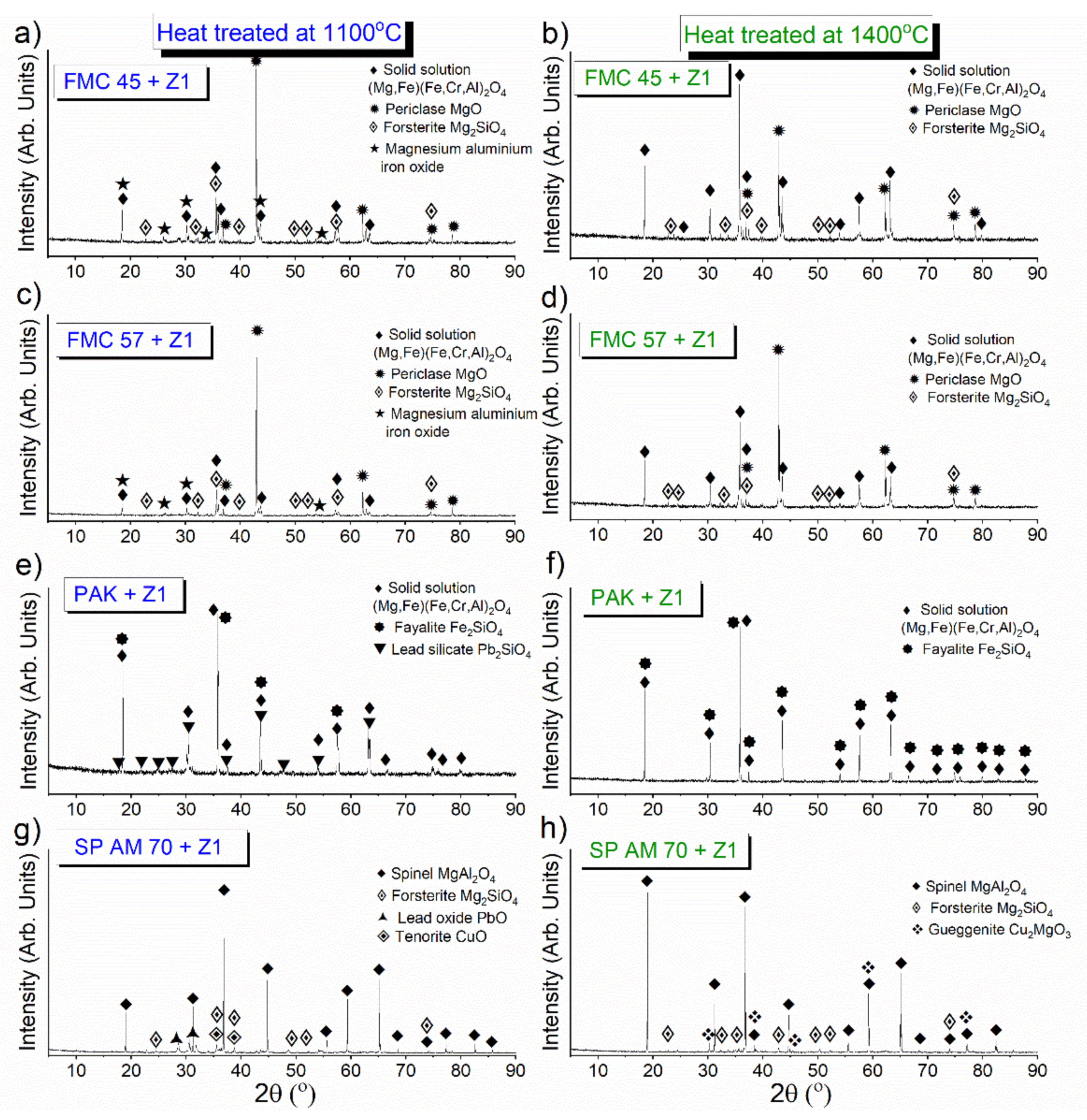
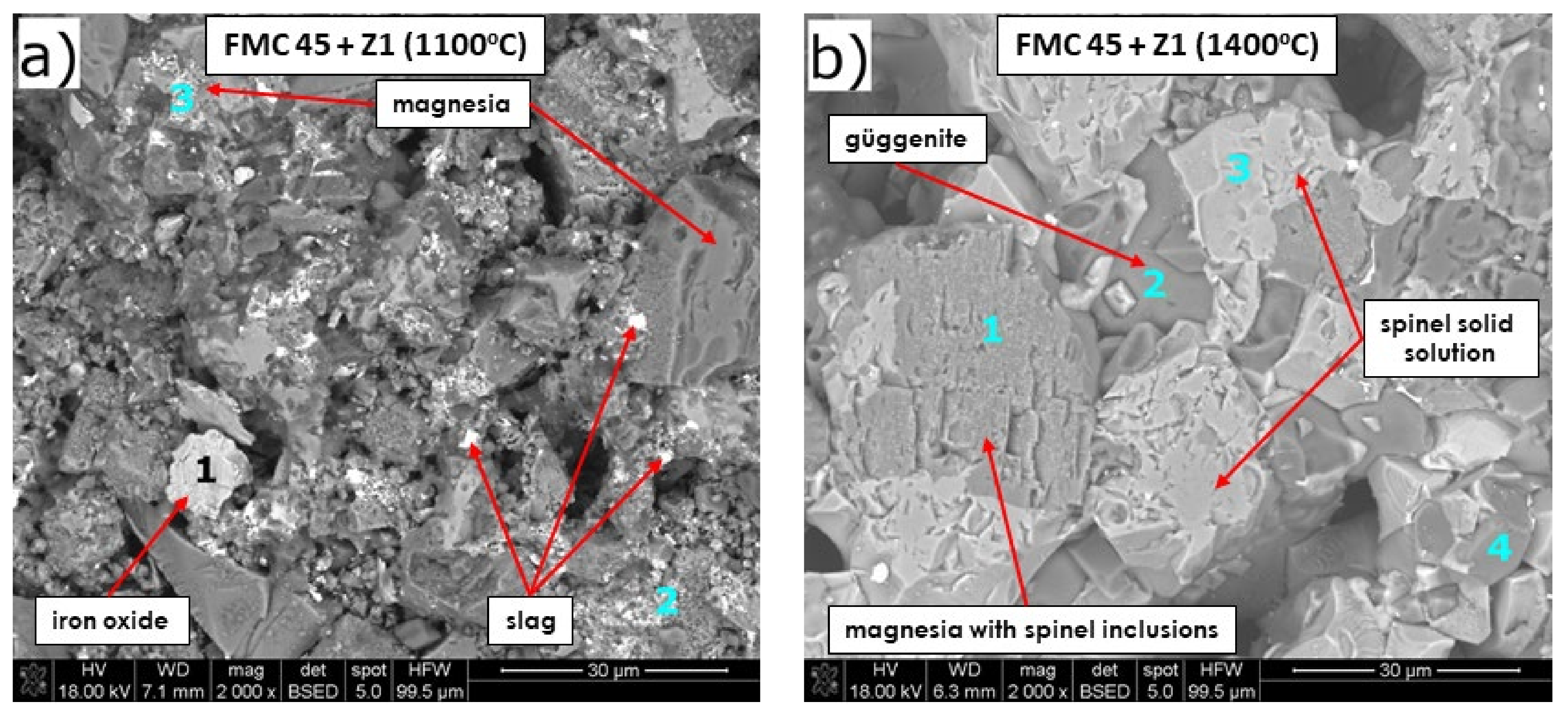
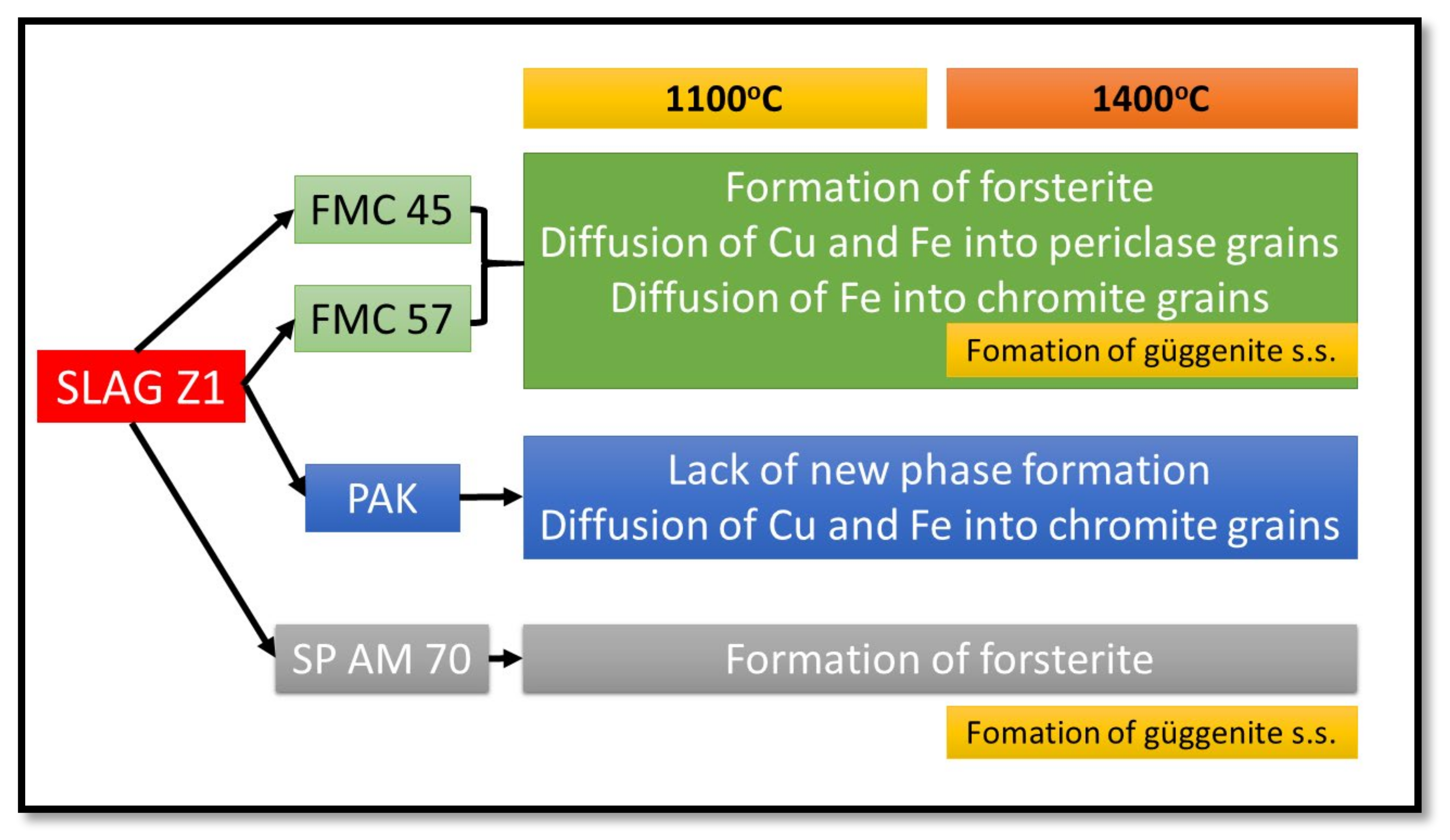
- From the results of both pellet and hot-stage microscopy corrosion tests, the most beneficial behavior was determined for FMC 45. It exhibited relatively stable dimensions during heating with 2% shrinkage, which corresponded to sample sintering at 1440 °C, being the highest sintering point among all tested raw materials. The only corrosion product was forsterite, which formed in slight amounts.
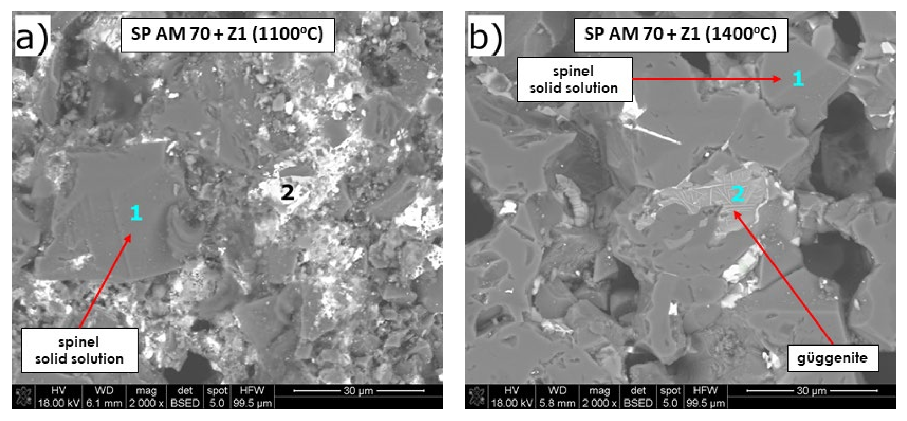
- Fused spinel (SP AM 70) was the least resistant to PbO-rich slag, as it started to sinter as first at 970 °C, followed by a fast and high 8% shrinkage of the material afterward. Güggenite solid solution formed due to the reaction between CuOx from slag and MgO from refractory. This phase is potentially detrimental, as it decomposes above 1062 °C, leading to the spalling of the material during reheating. Moreover, forsterite (Mg2SiO4) formed during corrosion can be harmful in larger amounts due to its significant volume.
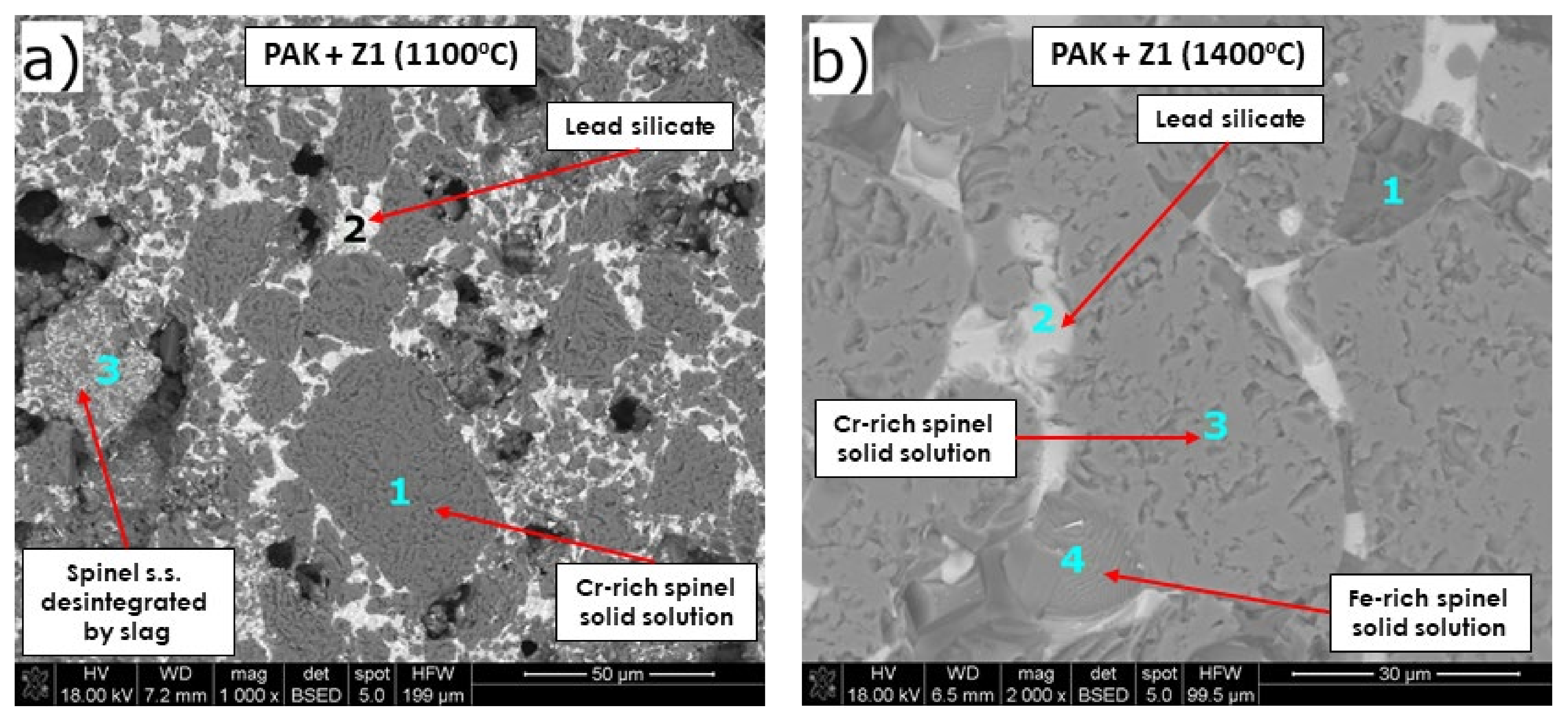
- Despite the different phase composition, PAK and FMC 57 showed comparable corrosion resistance and high-temperature behavior; thus, they constitute the most promising prospective raw materials for refractories dedicated to non-ferrous metallurgy where aggressive Pb-Cu-O slags occur.
Author Contributions
Funding
Data Availability Statement
Conflicts of Interest
References
- Malfliet, A.; Lotfian, S.; Scheunis, L.; Petkov, V.; Pandelaers, L.; Jones, P.T.; Blanpain, B. Degradation mechanisms and use of refractory linings in copper production processes: A critical review. J. Eur. Ceram. Soc. 2014, 34, 849–876. [Google Scholar] [CrossRef]
- Chen, L.; Li, S.; Jones, P.T.; Guo, M.; Blanpain, B.; Malfliet, A. Identification of magnesia-chromite refractory degradation mechanisms of secondary copper smelter linings. J. Eur. Ceram. Soc. 2016, 36, 2119–2132. [Google Scholar] [CrossRef]
- Petkov, V.; Jones, P.T.; Blanpain, B. Optimisation of an anode furnace refractory lining using distinct magnesia-chromite refractory types. World Metall.—ERZMETALL 2007, 60, 208–217. [Google Scholar]
- Gregurek, D.; Schmidl, J.; Reinharter, K.; Reiter, V.; Spanring, A. Copper Anode Furnace: Chemical, Mineralogical and Thermo-Chemical Considerations of Refractory Wear Mechanisms. JOM 2018, 70, 2428–2434. [Google Scholar] [CrossRef]
- Schlesinger, M.E. Refractories for copper production. Miner. Process. Extr. Metall. Rev. 1996, 16, 125–140. [Google Scholar] [CrossRef]
- Nadachowski, F. Zarys Technologii Materiałów Ogniotrwałych; Śląskie Wydawnictwa Techniczne: Katowice, Poland, 1995. [Google Scholar]
- Pashkeev, Y.; Vlasov, V.N. To the problem of phase equilibrium in PbO-SiO2 system. Izvestiia-vysshie Uchebnye Zavedeniia Tsvetnaia Metallurgiia 1999, 4, 3–6. [Google Scholar]
- Wu, M.P.; Eriksson, G.; Pelton, A.D. Calculated phase diagram of the system FeO-SiO2 in equilibrium with metallic Fe with total iron expressed as “FeO”. ISIJ Int. 1993, 33, 26–35. [Google Scholar] [CrossRef] [Green Version]
- Gabasiane, T.S.; Danha, G.; Mamvura, T.A.; Mashifana, T.; Dzinomwa, G. Characterization of copper slag for beneficiation of iron and copper. Heliyon 2021, 7, e06757. [Google Scholar] [CrossRef] [PubMed]
- Takeda, Y. Phase Diagram of CaO-FeO-Cu2O slag under copper saturation. Acta Crystallogr. 1956, 9, 211–225. [Google Scholar] [CrossRef]
- Bechta, S.V.; Krushinov, E.V.; Al’myashev, V.I.; Vitol, S.A.; Mezentseva, L.P.; Petrov, Y.B.; Lopukh, D.B.; Khabenskii, V.B.; Barrachin, M.; Hellmann, S. T-X phase diagram for the join Fe-Fe2O3. Russ. J. Inorg. Chem. 2006, 51, 325–331. [Google Scholar]
- Mcewan, N.; Courtney, T.; Parry, R.A.; Knupfer, P. Chromite—A cost-effective refractory raw material for refractories in various metallurgical applications. S. Afr. Pyrometallurgy 2011, 359–373. [Google Scholar]
- Seetharaman, S. Industrial Processes. In Treatise on Process Metallurgy; Elsevier: Amsterdam, The Netherlands, 2013; Volume 3. [Google Scholar]
- Petkov, V.; Jones, P.T.; Boydens, E.; Blanpain, B.; Wollants, P. Chemical corrosion mechanisms of magnesia-chromite and chrome-free refractory bricks by copper metal and anode slag. J. Eur. Ceram. Soc. 2007, 27, 2433–2444. [Google Scholar] [CrossRef]
- Golestani Fard, F.; Talimian, A. Improving Corrosion Behaviour of Magnesia-chrome Refractories by Addition of Nanoparticles. Refract. Worldforum 2014, 6, 93–98. [Google Scholar]
- Lotfian, N.; Nourbakhsh, A.A.; Mirsattari, S.N.; Mackenzie, K.J.D. Functionalization of nano-MgCr2O4 additives by silanol groups: A new approach to the development of magnesia-chrome refractories. Ceram. Int. 2021, 47, 31724–31731. [Google Scholar] [CrossRef]
- Lotfian, N.; Nourbakhsh, A.A.; Mirsattari, S.N.; Saberi, A.; Mackenzie, K.J.D. A comparison of the effect of nanostructured MgCr2O4 and FeCr2O4 additions on the microstructure and mechanical properties of direct-bonded magnesia-chrome refractories. Ceram. Int. 2020, 46, 747–754. [Google Scholar] [CrossRef]
- Pérez, I.; Moreno-Ventas, I.; Parra, R.; Ríos, G. Comparative analysis of refractory wear in the copper-making process by a novel (industrial) dynamic test. Ceram. Int. 2019, 45, 1535–1544. [Google Scholar] [CrossRef]
- Rigaud, M.; Palco, S.; Paransky, E. New refractory materials for the copper industry. In Proceedings of the Tehran International Conference on Refractories, Tehran, Iran, 4–6 May 2004. [Google Scholar]
- Pérez, I.; Moreno-Ventas, I.; Ríos, G. Post-mortem study of magnesia-chromite refractory used in Peirce-Smith Converter for copper-making process, supported by thermochemical calculations. Ceram. Int. 2018, 44, 13476–13486. [Google Scholar] [CrossRef]
- Pérez, I.; Moreno-Ventas, I.; Ríos, G. Chemical degradation of magnesia-chromite refractory used in the conversion step of the pyrometallurgical copper-making process: A thermochemical approach. Ceram. Int. 2018, 44, 18363–18375. [Google Scholar] [CrossRef]
- Gregurek, D.; Prietl, T.; Breyner, S.B.; Ressler, A.; Berghofer, N.M. Innovative Magnesia-Chrome Fused Grain Material For Non- Ferrous Metals Refractory Applications. S. Afr. Inst. Min. Metall. 2012, 251–260. [Google Scholar]
- Xu, L.; Chen, M.; Wang, N.; Gao, S. Chemical wear mechanism of magnesia-chromite refractory for an oxygen bottom-blown copper-smelting furnace: A post-mortem analysis. Ceram. Int. 2021, 47, 2908–2915. [Google Scholar] [CrossRef]
- Lange, M.; Garbers-Craig, A.M.; Cromarty, R. Wear of magnesia-chrome refractory bricks as a function of matte temperature. J. S. Afr. Inst. Min. Metall. 2014, 114, 4. [Google Scholar]
- Chen, L.; Guo, M.; Shi, H.; Huang, S.; Jones, P.T.; Blanpain, B.; Malfliet, A. Effect of ZnO level in secondary copper smelting slags on slag/magnesia-chromite refractory interactions. J. Eur. Ceram. Soc. 2016, 36, 1821–1828. [Google Scholar] [CrossRef]
- Chen, L.; Guo, M.; Shi, H.; Scheunis, L.; Jones, P.T.; Blanpain, B.; Malfliet, A. The influence of ZnO in fayalite slag on the degradation of magnesia-chromite refractories during secondary Cu smelting. J. Eur. Ceram. Soc. 2015, 35, 2641–2650. [Google Scholar] [CrossRef]
- Xu, L.; Chen, M.; Wang, N.; Gao, S.; Wu, Y. Degradation mechanisms of magnesia-chromite refractory bricks used in oxygen side-blown reducing furnace. Ceram. Int. 2020, 46, 17315–17324. [Google Scholar] [CrossRef]
- Hu, S.; Huang, A.; Jia, Q.; Zhang, S.; Chen, L. Degradation of magnesia-chromite refractory in ZnO-containing ferrous calcium silicate slags. Ceram. Int. 2021, 47, 11276–11284. [Google Scholar] [CrossRef]
- Chen, L.; Malfliet, A.; Vleugels, J.; Blanpain, B.; Guo, M. Degradation mechanisms of alumina-chromia refractories for secondary copper smelter linings. Corros. Sci. 2018, 136, 409–417. [Google Scholar] [CrossRef]
- Jiang, Y.; Chen, M.; Chen, J.; Zhao, B. Interactions of MgO·Al2O3 spinel with Cu, Cu2O and copper matte at high temperature. Ceram. Int. 2018, 44, 14108–14112. [Google Scholar] [CrossRef]
- Hellstén, N.; Taskinen, P. Experimental phase relations between MgO-saturated magnesium-aluminate spinel (MgAl2O4) and CuOx-rich liquid. Ceram. Int. 2017, 43, 11116–11122. [Google Scholar] [CrossRef]
- De Wilde, E.; Bellemans, I.; Campforts, M.; Guo, M.; Blanpain, B.; Moelans, N.; Verbeken, K. Sessile drop evaluation of high temperature copper/spinel and slag/spinel interactions. Trans. Nonferrous Met. Soc. China 2016, 26, 2770–2783. [Google Scholar] [CrossRef]
- Jedynak, L.; Wojsa, J.; Podwórny, J.; Wala, T. Refractories from MgO-Al2O3-SnO2 system for metallurgical applications. In Proceedings of the 11th International Conference and Exhibition of the European Ceramic Society, Krakow, Poland, 21–25 June 2009; Volume 2009, pp. 812–817. [Google Scholar]
- Jedynak, L.; Wojsa, J. Bezchromowe, niewypalane materiały ogniotrwałe. Pr. Inst. Szkła Ceram. Mater. Ogniotrwałych i Bud. 2010, 3, 69–79. [Google Scholar]
- Yurkov, A.; Malakho, A.; Avdeev, V. Corrosion behavior of silicon nitride bonded silicon carbide refractory material by molten copper and copper slag. Ceram. Int. 2017, 43, 4241–4245. [Google Scholar] [CrossRef]
- Gómez-Rodríguez, C.; Antonio-Zárate, Y.; Revuelta-Acosta, J.; Verdej, L.F.; Fernández-González, D.; López-Perales, J.F.; Rodríguz-Castellanos, E.A.; García-Quiñonez, L.V.; Castillo-Rodríguez, G.A. Research and development of novel refractory of MgO doped with ZrO2 nanoparticles for copper slag resistance. Materials 2021, 14, 2277. [Google Scholar] [CrossRef]
- Hellstén, N.; Hamuyuni, J.; Taskinen, P. High-temperature phase equilibria of Cu-O-MgO system in air. Thermochim. Acta 2016, 623, 107–111. [Google Scholar] [CrossRef]
- Scheunis, L.; Campforts, M.; Jones, P.T.; Blanpain, B.; Malfliet, A. Spinel saturation of a PbO based slag as a method to mitigate the chemical degradation of magnesia-chromite bricks. J. Eur. Ceram. Soc. 2016, 36, 4291–4299. [Google Scholar] [CrossRef]
- Scheunis, L.; Fallah-Mehrjardi, A.; Campforts, M.; Jones, P.T.; Blanpain, B.; Malfliet, A.; Jak, E. The effect of a temperature gradient on the phase formation inside a magnesia-chromite refractory in contact with a non-ferrous PbO-SiO2-MgO slag. J. Eur. Ceram. Soc. 2015, 35, 2933–2942. [Google Scholar] [CrossRef]
- Scheunis, L.; Fallah Mehrjardi, A.; Campforts, M.; Jones, P.T.; Blanpain, B.; Jak, E. The effect of phase formation during use on the chemical corrosion of magnesia-chromite refractories in contact with a non-ferrous PbO-SiO2 based slag. J. Eur. Ceram. Soc. 2014, 34, 1599–1610. [Google Scholar] [CrossRef]
- Scheunis, L.; Campforts, M.; Jones, P.T.; Blanpain, B.; Malfliet, A. The influence of slag compositional changes on the chemical degradation of magnesia-chromite refractories exposed to PbO-based non-ferrous slag saturated in spinel. J. Eur. Ceram. Soc. 2015, 35, 347–355. [Google Scholar] [CrossRef]
- Ludwig, M.; Śnieżek, E.; Jastrzębska, I.; Piwowarczyk, A.; Wojteczko, A.; Li, Y.; Szczerba, J. Corrosion of magnesia-chromite refractory by PbO-rich copper slags. Corros. Sci. 2022, 195, 109949. [Google Scholar] [CrossRef]
- Galos, K. Surowce krajowego przemysłu materiałów ogniotrwałych w świetle przemian gospodarczych; Polska Akademia Nauk: Kraków, Poland, 1999. [Google Scholar]
- Jung, I.; Decterov, S.A.; Pelton, A.D. Critical Thermodynamic Evaluation and Optimization of the MgO-Al2O3, CaO-MgO-Al2O3, and MgO-Al2O3-SiO2 systems. J. Phase Equilibria Diffus. 2004, 25, 329–345. [Google Scholar] [CrossRef]
- Beals, R.J.; Cook, R.L. Directional Dilatation of Crystal Lattices at Elevated Temperatures. J. Am. Ceram. Soc. 1957, 40, 279–284. [Google Scholar] [CrossRef]
- Wu, G.; Yan, W.; Schafföner, S.; Lin, X.; Ma, S.; Zhai, Y.; Liu, X.; Xu, L. Effect of magnesium aluminate spinel content of porous aggregates on cement clinker corrosion and adherence properties of lightweight periclase-spinel refractories. Constr. Build. Mater. 2018, 185, 102–109. [Google Scholar] [CrossRef]
- Hartenstein, J.; Gueguen, E.; Moulin, J.; Schepers, A. Imroving properties of magnesia-aluminate spinel bricks for cement rotary kilns by using micro-fine MgO particles. In Proceedings of the UNITECR Congress, Santiago, Chile, 26–29 September 2017. [Google Scholar]
- Ohno, M.; Yoshikawa, S.; Toda, H.; Fujii, M.; Chiba, H.; Ozeki, F. Magnesia-Spinel Brick With Good Coating Adhesion and High Resistance To Corrosion and Spalling for Cement Rotary Kilns. In Proceedings of the UNITECR Congress, Santiago, Chile, 26–29 September 2017. [Google Scholar]
- Braulio, M.A.L.; Martinez, A.G.T.; Luz, A.P.; Liebske, C.; Pandolfelli, V.C. Basic slag attack of spinel-containing refractory castables. Ceram. Int. 2011, 37, 1935–1945. [Google Scholar] [CrossRef]
- Sako, E.Y.; Braulio, M.A.L.; Zinngrebe, E.; Van Der Laan, S.R.; Pandolfelli, V.C. Fundamentals and applications on in situ spinel formation mechanisms in Al2O3-MgO refractory castables. Ceram. Int. 2012, 38, 2243–2251. [Google Scholar] [CrossRef]
- Luz, A.P.; Braulio, M.A.L.; Tomba Martinez, A.G.; Pandolfelli, V.C. Slag attack evaluation of in situ spinel-containing refractory castables via experimental tests and thermodynamic simulations. Ceram. Int. 2012, 38, 1497–1505. [Google Scholar] [CrossRef]
- Sako, E.Y.; Braulio, M.A.L.; Pandolfelli, V.C. The corrosion resistance of microsilica-containing Al2O3-MgO and Al2O3-spinel castables. Ceram. Int. 2012, 38, 4783–4789. [Google Scholar] [CrossRef]
- Panna, W.; Wyszomirski, P.; Kohut, P. Application of hot-stage microscopy to evaluating sample morphology changes on heating. J. Therm. Anal. Calorim. 2016, 125, 1053–1059. [Google Scholar] [CrossRef] [Green Version]
- Ludwig, M.; Wiśniewska, K.; Śnieżek, E.; Jastrzębska, I.; Prorok, R.; Szczerba, J. Effect of the chemical composition of slag on the corrosion of calcium zirconate material. Mater. Chem. Phys. 2021, 258, 123844. [Google Scholar] [CrossRef]
- Serry, M.A.; Othman, A.G.M.; Girgis, L.G.; Telle, R. Assessment of coclinkered shaped magnesite-chromite refractories processed from Egyptian materials. Am. Ceram. Soc. Bull. 2007, 86, 9101–9106. [Google Scholar]
- Tripathy, S.K.; Murthy, Y.R.; Singh, V.; Suresh, N. Processing of Ferruginous Chromite Ore by Dry High-Intensity Magnetic Separation. Miner. Process. Extr. Metall. Rev. 2016, 37, 196–210. [Google Scholar] [CrossRef]
- Motasim, M.; Al-Tigani, H.; Mohamed, A.A.; Abdullah, A.; Seifelnasr, S. Mineralogical and Chemical Characterization of Disseminated Low-Grade Sudanese Chromite Ore in Gedarif State at Umm Saqata-Qala Elnahal. J. Environ. Anal. Chem. 2019, 6, 1000261. [Google Scholar] [CrossRef]
- Gorai, B.; Jana, R.K. Premchand, Characteristics and utilisation of copper slag—A review. Resour. Conserv. Recycl. 2003, 39, 299–313. [Google Scholar] [CrossRef]
- Wang, X.; Geysen, D.; Padilla, S.V.; D’Hoker, N.; Van Gerven, T.; Blanpain, B. Characterization of Copper Slag. In REWAS 2013 Enabling Materials Resource Sustainability; Springer: Cham, Switzerland, 2013; pp. 54–68. [Google Scholar] [CrossRef]
- Gregurek, D.; Majcenovic, C.; Budna, K.; Schmidl, J.; Spanring, A. Wear Phenomena in Non-Ferrous Metal Furnaces; Springer International Publishing: Cham, Switzerland, 2018. [Google Scholar]
- Gregurek, D.; Wenzl, C.; Reiter, V.; Studnicka, H.L.; Spanring, A. Slag Characterization: A Necessary Tool for Modeling and Simulating Refractory Corrosion on a Pilot Scale. JOM 2014, 66, 1677–1686. [Google Scholar] [CrossRef]
- Madhusudhan Rao, A.S.; Narender, K. Studies on thermophysical properties of CaO and MgO by γ -ray attenuation. J. Thermodyn. 2014, 2014, 123478. [Google Scholar] [CrossRef] [Green Version]
- Paranthaman, M.; David, K.A.; Lindemer, T.B. Phase equilibria of the MgO-Cu2O-CuO system. Mater. Res. Bull. 1997, 32, 165–173. [Google Scholar] [CrossRef]
- Beattie, P. Olivine-melt and orthopyroxene-melt equilibria. Contrib. Mineral. Petrol. 1993, 115, 103–111. [Google Scholar] [CrossRef]
- Najem, I.A.; Edrees, S.J.; Rasin, F.A. Structural and Magnetic Characterisations of Pb-Doped MgO Nanoparticles by a Modified Pechini Method. IOP Conf. Ser. Mater. Sci. Eng. 2020, 987, 012027. [Google Scholar] [CrossRef]
- Chen, S.; Zhao, B.; Jak, E.; Hayes, P.C. Experimental study of phase equilibria in the PbO-MgO-SiO2 system. Metall. Mater. Trans. B 2001, 32, 11–16. [Google Scholar] [CrossRef]
- O’Neill, H.S.C.; Navrotsky, A. Simple spinels; crystallographic parameters, cation radii, lattice energies, and cation distribution. Am. Mineral. 1983, 68, 181–194. [Google Scholar]
- Jastrzębska, I.; Szczerba, J.; Błachowski, A.; Stoch, P. Structure and microstructure evolution of hercynite spinel (Fe2+Al2O4) after annealing treatment. Eur. J. Mineral. 2017, 29, 62–71. [Google Scholar] [CrossRef]
- Jastrzȩbska, I.; Szczerba, J.; Stoch, P. Structural and microstructural study on the Arc-Plasma Synthesized (APS) FeAl2O4-MgAl2O4 transitional refractory compound. High Temp. Mater. Process. 2017, 36, 299–303. [Google Scholar] [CrossRef]
- Jastrzebska, I.; Bodnar, W.; Witte, K.; Burkel, E.; Stoch, P.; Szczerba, J. Structural properties of Mn-substituted hercynite. Nukleonika 2017, 62, 95–100. [Google Scholar] [CrossRef] [Green Version]
- Chen, M.; Chen, J.; Zhao, B. Corrosion resistances of Cr-free refractories to copper smelting slags. In Advances in Molten Slags, Fluxes, Salts, Proceedings of the 10th International Conference on Molten Slags, Fluxes Salts, Seattle, DC, USA, 22–25 May 2016; Springer: Cham, Switzerland, 2016; pp. 1101–1108. [Google Scholar] [CrossRef]
- Kirgintsev, A.N. To the thermodynamics of the FeO-SiO2 phase diagram. Geochem. Int. 1998, 36, 874–876. [Google Scholar]
- Schramm, L.; Behr, G.; Löser, W.; Wetzig, K. Thermodynamic reassessment of the Cu-O phase diagram. J. Phase Equilib. Diff. 2005, 26, 605–612. [Google Scholar] [CrossRef]
- Chen, M.; Jiang, Y.; Cui, Z.; Wei, C.; Zhao, B. Chemical Degradation Mechanisms of Magnesia–Chromite Refractories in the Copper Smelting Furnace. JOM 2018, 70, 2443–2448. [Google Scholar] [CrossRef]
- Liu, G.; Li, Y.; Zhu, T.; Xu, Y.; Liu, J.; Sang, S.; Li, Q.; Li, Y. Influence of the atmosphere on the mechanical properties and slag resistance of magnesia-chrome bricks. Ceram. Int. 2020, 46, 11225–11231. [Google Scholar] [CrossRef]
- Shannon, R.D.; Prewitt, C.T. Effective ionic radii in oxides and fluorides. Acta Crystallogr. Sect. B Struct. Crystallogr. Cryst. Chem. 1969, 25, 925–946. [Google Scholar] [CrossRef]
- Available online: https://www.sciencedirect.com/topics/chemistry/copper-oxide (accessed on 10 November 2021).
- Reinharter, K.; Gregurek, D.; Majcenovic, C.; Schmidl, J.; Spanring, A. Influence of arsenic on the chemical wear of magnesia-chromite refractories in copper smelting furnaces. In Extraction; The Minerals, Metals & Materials Series; Springer: Cham, Switzerland, 2018. [Google Scholar]


| Oxide | As2O3 | PbO | CuO | Fe2O3 | SnO2 | SiO2 | ZnO | Al2O3 | CaO | MgO |
|---|---|---|---|---|---|---|---|---|---|---|
| Melting point [°C] | 312 | 897 | 1085 | 1565 | 1630 | 1723 | 1975 | 2020 | 2625 | 2825 |
| Oxide | Magnesia–Chromite Co-Clinker FMC 45 | Magnesia–Chromite Co-Clinker FMC 57 | Pakistani Chromite Ore PAK | Fused Spinel SP AM 70 |
|---|---|---|---|---|
| MgO | 51.76 | 61.89 | 17.18 | 27.86 |
| Al2O3 | 6.18 | 5.14 | 11.69 | 70.59 |
| Cr2O3 | 24.87 | 19.40 | 49.76 | - |
| Fe2O3 | 15.04 | 10.48 | 16.32 | 0.40 |
| SiO2 | 0.92 | 1.37 | 3.91 | 0.17 |
| CaO | 0.76 | 1.33 | 0.26 | 0.69 |
| V2O5 | 0.06 | 0.07 | 0.09 | - |
| Others | 0.41 | 0.32 | 0.79 | 0.29 |
| Oxide | PbO | Fe2O3 | CuO | SiO2 | As2O3 | CaO | Al2O3 | ZnO | Others |
| wt. [%] | 39.10 | 18.20 | 15.60 | 14.00 | 3.35 | 3.34 | 1.58 | 1.18 | 3.65 |
| FMC 45 | FMC 57 | PAK | SP AM 70 | |
|---|---|---|---|---|
| Room temperature |  |  | 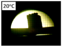 | 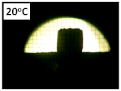 |
| Sintering temperature | 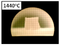 | 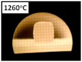 | 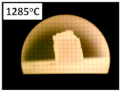 | 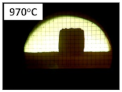 |
| Sample at the end of the test | 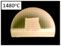 | 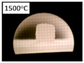 | 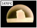 | 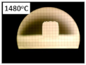 |
| Temperature | FMC 45 + Z1 | FMC 57 + Z1 | PAK + Z1 | SP AM 70 + Z1 |
|---|---|---|---|---|
| 1100 °C | Solid solution (Mg,Fe)(Fe,Cr,Al)2O4 | Spinel MgAl2O4 | ||
| Periclase MgO | Fayalite Fe2SiO4 | Lead Oxide PbO | ||
| Forsterite Mg2SiO4 | Lead silicate Pb2SiO4 | Forsterite Mg2SiO4 | ||
| Magnesium aluminum oxide | - | Tenorite CuO | ||
| 1400 °C | Solid solution (Mg,Fe)(Fe,Cr,Al)2O4 | Spinel MgAl2O4 | ||
| Periclase MgO | Fayalite Fe2SiO4 | Forsterite Mg2SiO4 | ||
| Forsterite Mg2SiO4 | - | Güggenite Cu2MgO3 | ||
| Figure No. | Point | Phase | Chemical Composition, wt./mol% * | ||||||||
|---|---|---|---|---|---|---|---|---|---|---|---|
| Pb | Cu | Mg | Cr | Al | Si | Fe | As | O | |||
| Figure 7a | 1 | Fe-Cr-O solid solution | 1.1/0.2 | - | 1.2/2.3 | 12.2/10.8 | 0.9/1.5 | 2.7/4.2 | 70.0/57.9 | - | 4.3/12.5 |
| 2 | - | 16.4/2.4 | 1.0/0.5 | 21.6/26.6 | 6.1/3.5 | 2.9/3.2 | 3.3/3.5 | 18.4/9.9 | - | 23.8/44.5 | |
| 3 | - | 19.0/2.6 | 2.3/1.0 | 25.1/28.9 | 3.8/2.0 | 1.9/2.0 | 5.7/5.7 | 10.1/5.1 | - | 28.3/49.7 | |
| Figure 7b | 1 | MgO with (Mg,Fe)(Fe,Cr,Al) spinel inclusions | 0.8/0.1 | 6.1/2.3 | 44.9/44.4 | 4.6/2.1 | 1.0/0.9 | 0.2/0.1 | 8.4/3.6 | 1.7/0.6 | 29.5/44.3 |
| 2 | Güggenite s.s. | 0.9/0.2 | 33.1/19.9 | 18.3/28.8 | 8.2/6.0 | - | 1.2/1.6 | 10.0/6.8 | - | 10.5/25.0 | |
| 3 | Mg-rich spinel s.s. Mg-Fe-Cr-Al-O | 1.3/0.2 | 1.3/0.5 | 15.9/16.7 | 11.4/5.6 | 7.4/7.1 | 1.1/1.0 | 20.6/9.5 | - | 34.9/55.9 | |
| 4 | Cr-rich spinel solid solution Mg-Fe-Cr-Al-O | 1.1/0.2 | 0.9/0.4 | 16.0/17.5 | 17.4/8.9 | 7.2/7.1 | 0.3/0.3 | 16.4/7.8 | 3.2/1.1 | 32.5/54.1 | |
| Figure No. | Point | Phase | Chemical Composition, wt./mol% * | ||||||||
|---|---|---|---|---|---|---|---|---|---|---|---|
| Pb | Cu | Mg | Cr | Al | Si | Fe | As | O | |||
| Figure 8a | 1 | MgO with (Mg,Fe)(Fe,Cr,Al) spinel inclusions | 1.1/0.1 | 5.5/2.0 | 51.7/50.2 | 2.7/1.2 | 0.8/0.7 | 0.6/0.5 | 6.4/2.7 | 1.8/0.6 | 27.5/40.6 |
| 2 | Fe-rich spinel s.s.Mg-Fe-Cr-Al-O | 1.0/0.1 | 2.7/1.2 | 16.5/18.9 | 13.5/7.2 | 5.5/5.6 | 0.1/0.1 | 30.2/15.0 | - | 29.1/50.6 | |
| 3 | MgO s.s. | - | 3.4/1.1 | 56.4/49.4 | 0.9/0.4 | - | 0.3/0.2 | 2.5/1.0 | - | 35.4/47.2 | |
| 4 | - | 33.2/6.0 | 2.8/1.6 | 17.4/26.7 | 6.4/4.6 | 0.8/1.1 | 5.9/7.8 | 4.3/2.9 | 4.1/2.0 | 15.8/37.0 | |
| 5 | Fe-rich spinel s.s.Mg-Fe-Cr-Al-O | 6.1/0.8 | 1.5/0.6 | 12.2/13.6 | 9.7/5.1 | 4.2/4.2 | - | 23.4/11.3 | - | 32.4/54.8 | |
| Figure 8b | 1 | MgO with spinel inclusions | 0.4/0.1 | 0.7/0.3 | 30.7/32.4 | 15.2/7.5 | 4.6/4.4 | 0.6/0.5 | 16.0/7.4 | - | 28.6/45.8 |
| 2 | Cr-rich spinel s.s.Mg-Fe-Cr-Al-O | 0.4/0.1 | 0.7/0.3 | 15.6/17.2 | 32.5/16.7 | 7.0/6.9 | 0.6/0.6 | 5.8/2.8 | 1.9/0.7 | 31.6/52.6 | |
| 3 | Spinel s.s. Mg-Fe-Cr-Al-O | - | 1.4/0.6 | 17.2/19.7 | 23.6/12.7 | 7.2/7.4 | 0.2/0.2 | 20.0/10.0 | - | 27.1/47.2 | |
| Figure No. | Point | Phase | Chemical Composition, wt./mol% * | ||||||||
|---|---|---|---|---|---|---|---|---|---|---|---|
| Pb | Cu | Mg | Cr | Al | Si | Fe | As | O | |||
| Figure 9a | 1 | Cr-rich spinel solid solution Mg-Fe-Cr-Al-O | - | 5.8/2.7 | 10.7/13.2 | 40.1/23.0 | 8.1/8.9 | 0.4/0.4 | 3.6/1.9 | 3.5/1.4 | 25.1/46.7 |
| 2 | Lead silicate Pb2SiO4 s.s. | 51.8/11.7 | 3.5/2.6 | 1.9/3.7 | 2.1/1.9 | 3.4/5.9 | 13.7/22.8 | 2.7/2.3 | - | 13.5/39.5 | |
| 3 | - | 19.5/3.3 | 4.6/2.6 | 7.1/10.3 | 20.4/13.8 | 4.0/5.2 | 5.3/6.6 | 13.9/8.8 | - | 20.7/45.6 | |
| Figure 9b | 1 | Olivine (Ca,Mg,Fe)2SiO4 ** | 0.4/0.4 | 0.5/0.2 | 9.6/9.8 | 1.5/0.7 | 3.9/3.6 | 25.6/22.6 | 6.9/3.1 | - | 30.5/47.1 |
| 2 | Lead silicate Pb2SiO4 s.s. | 35.9/6.3 | 2.7/1.5 | 1.7/2.5 | 2.9/2.0 | 6.0/8.1 | 19.5/25.3 | 3.1/2.0 | - | 19.4/44.2 | |
| 3 | Cr-rich spinel s.s. Mg-Fe-Cr-Al-O | - | 4.9/2.5 | 9.9/13.0 | 44.3/27.2 | 4.0/4.7 | - | 9.4/5.4 | 2.1/0.9 | 22.1/44.1 | |
| 4 | Fe,Cr-rich spinel s.s. Mg-Fe-Cr-Al-O | 1.7/0.4 | 7.1/4.8 | 6.1/10.6 | 32.9/27.0 | 2.4/3.7 | 0.9/1.3 | 34.6/26.4 | 2.7/1.5 | 7.8/20.9 | |
| Figure No. | Point | Phase | Chemical Composition, wt./mol% * | ||||||||
|---|---|---|---|---|---|---|---|---|---|---|---|
| Pb | Cu | Mg | Cr | Al | Si | Fe | As | O | |||
| Figure 10a | 1 | Spinel MgAl2O4 s.s. | 0.7/0.1 | 0.6/0.2 | 18.1/16.4 | 0.5/0.2 | 43.8/35.8 | 0.3/0.2 | 0.7/0.3 | - | 33.0/45.5 |
| 2 | - | 5.3/0.7 | 15.3/6.2 | 23.0/24.2 | 0.3/0.2 | 2.0/1.9 | 14.5/13.2 | 2.0/0.9 | - | 30.5/48.9 | |
| Figure 10b | 1 | Spinel MgAl2O4 s.s. | - | 1.3/0.5 | 16.7/15.5 | 0.5/0.2 | 40.5/33.7 | 0.2/0.2 | 5.1/2.0 | - | 33.2/46.6 |
| 2 | Güggenite s.s. | - | 25.0/10.4 | 41.5/45.3 | 0.2/0.1 | 0.4/0.4 | - | 4.2/2.0 | - | 23.3/38.6 | |
Publisher’s Note: MDPI stays neutral with regard to jurisdictional claims in published maps and institutional affiliations. |
© 2022 by the authors. Licensee MDPI, Basel, Switzerland. This article is an open access article distributed under the terms and conditions of the Creative Commons Attribution (CC BY) license (https://creativecommons.org/licenses/by/4.0/).
Share and Cite
Ludwig, M.; Śnieżek, E.; Jastrzębska, I.; Prorok, R.; Li, Y.; Liao, N.; Nath, M.; Vlček, J.; Szczerba, J. Corrosion Resistance of MgO and Cr2O3-Based Refractory Raw Materials to PbO-Rich Cu Slag Determined by Hot-Stage Microscopy and Pellet Corrosion Test. Materials 2022, 15, 725. https://doi.org/10.3390/ma15030725
Ludwig M, Śnieżek E, Jastrzębska I, Prorok R, Li Y, Liao N, Nath M, Vlček J, Szczerba J. Corrosion Resistance of MgO and Cr2O3-Based Refractory Raw Materials to PbO-Rich Cu Slag Determined by Hot-Stage Microscopy and Pellet Corrosion Test. Materials. 2022; 15(3):725. https://doi.org/10.3390/ma15030725
Chicago/Turabian StyleLudwig, Maciej, Edyta Śnieżek, Ilona Jastrzębska, Ryszard Prorok, Yawei Li, Ning Liao, Mithun Nath, Jozef Vlček, and Jacek Szczerba. 2022. "Corrosion Resistance of MgO and Cr2O3-Based Refractory Raw Materials to PbO-Rich Cu Slag Determined by Hot-Stage Microscopy and Pellet Corrosion Test" Materials 15, no. 3: 725. https://doi.org/10.3390/ma15030725
APA StyleLudwig, M., Śnieżek, E., Jastrzębska, I., Prorok, R., Li, Y., Liao, N., Nath, M., Vlček, J., & Szczerba, J. (2022). Corrosion Resistance of MgO and Cr2O3-Based Refractory Raw Materials to PbO-Rich Cu Slag Determined by Hot-Stage Microscopy and Pellet Corrosion Test. Materials, 15(3), 725. https://doi.org/10.3390/ma15030725