
Investigation of Weld Root Defects in High-Power Full-Penetration Laser Welding of High-Strength Steel


 ,
,  and
and
Abstract
:1. Introduction
2. Materials and Methods
2.1. Materials
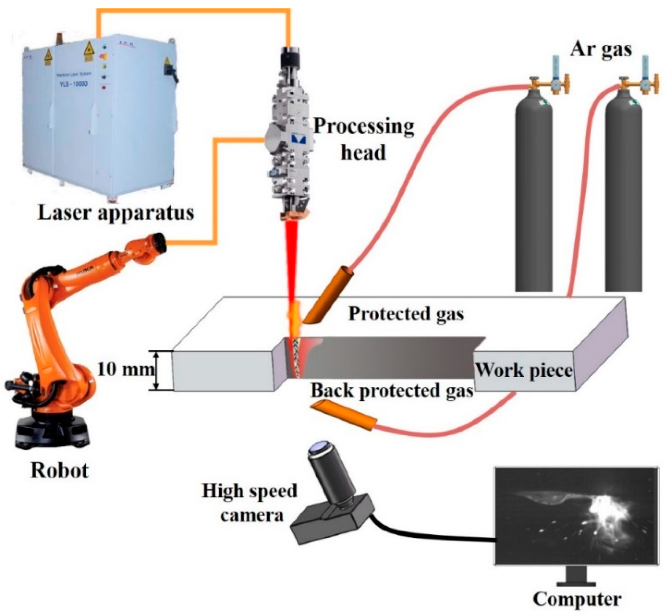
2.2. Experimental Method
3. Results and Discussion
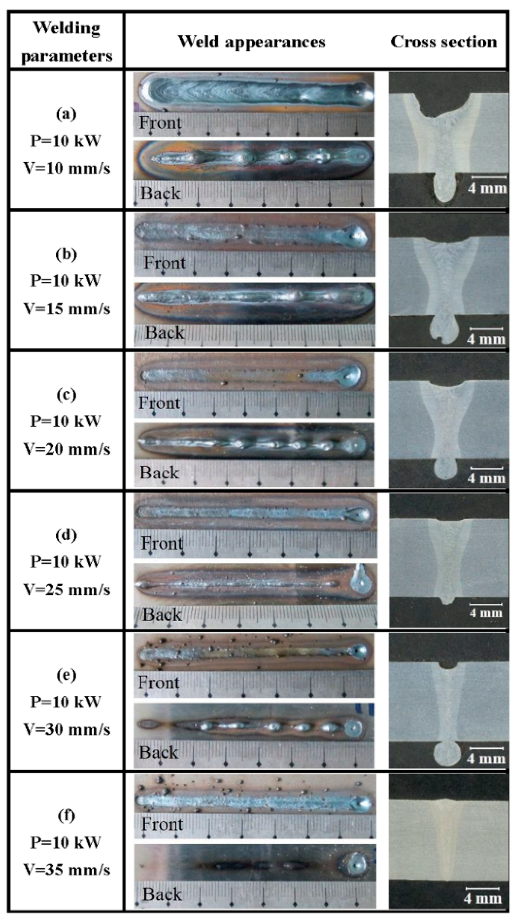
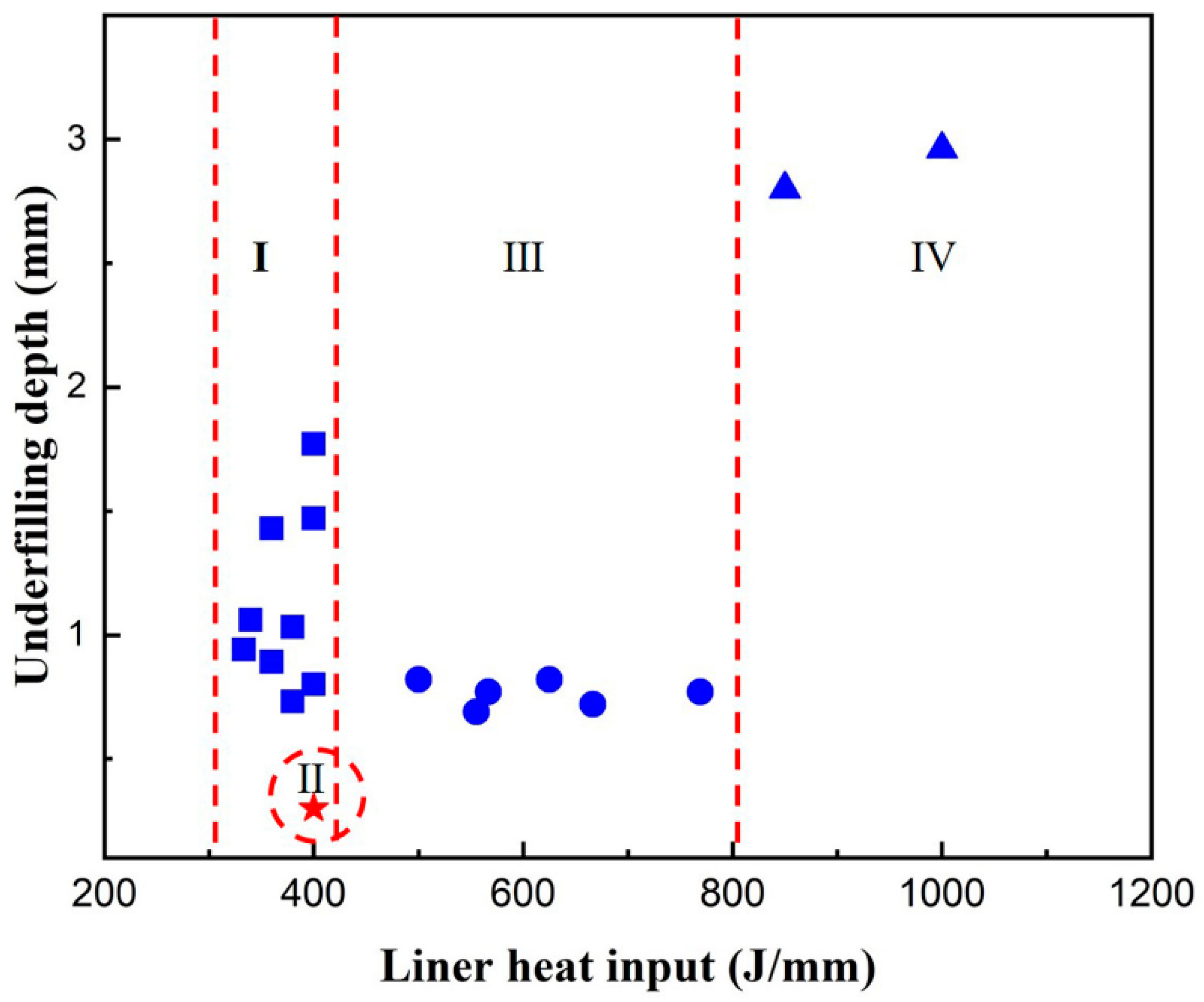
3.1. Effect of Welding Parameters on Weld-Root Defects
- -
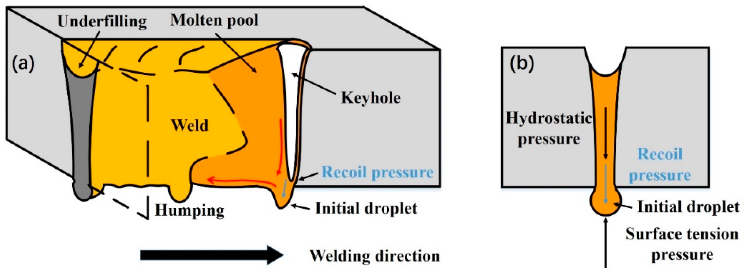
- Type I: a narrow weld bead with deep underfilling and intermittent humps at a low linear heat input. This type of weld-root appearance could be named as weld-root humping, which corresponds to Figure 2e;
- -
- Type II: a sound weld bead with the smooth weld-root appearance with a narrow linear heat input window. In addition, there are some limits of welding parameters even within the linear heat input window. This type of weld-root appearance corresponds to Figure 2d;
- -
- -
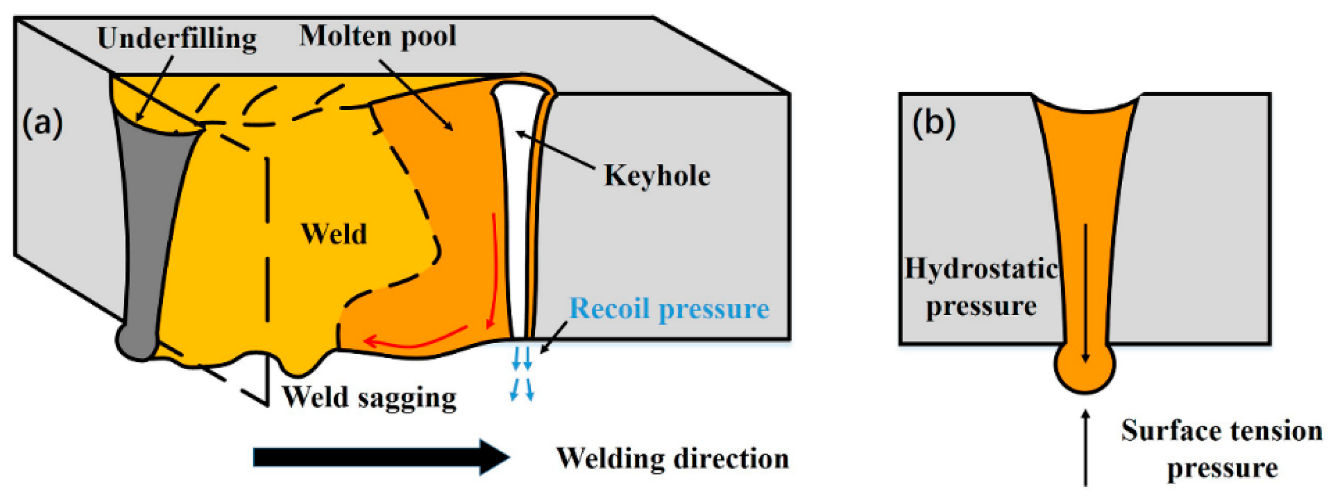
- Type IV: a wide weld bead with a deeper underfilling than Type III;, excessive root penetration melt metal and some big melt droplets. This type of weld-root appearance is the excessive Type III, and could be named as excessive weld sagging, which corresponds to Figure 2a.
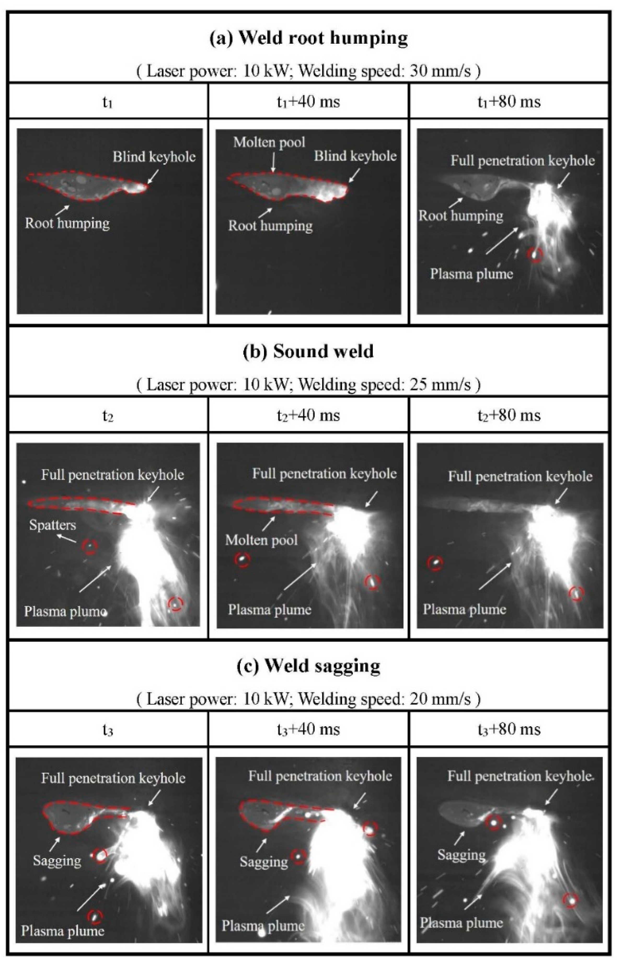
3.2. Effect of Welding Parameters on Bottom Molten Pool Behaviors
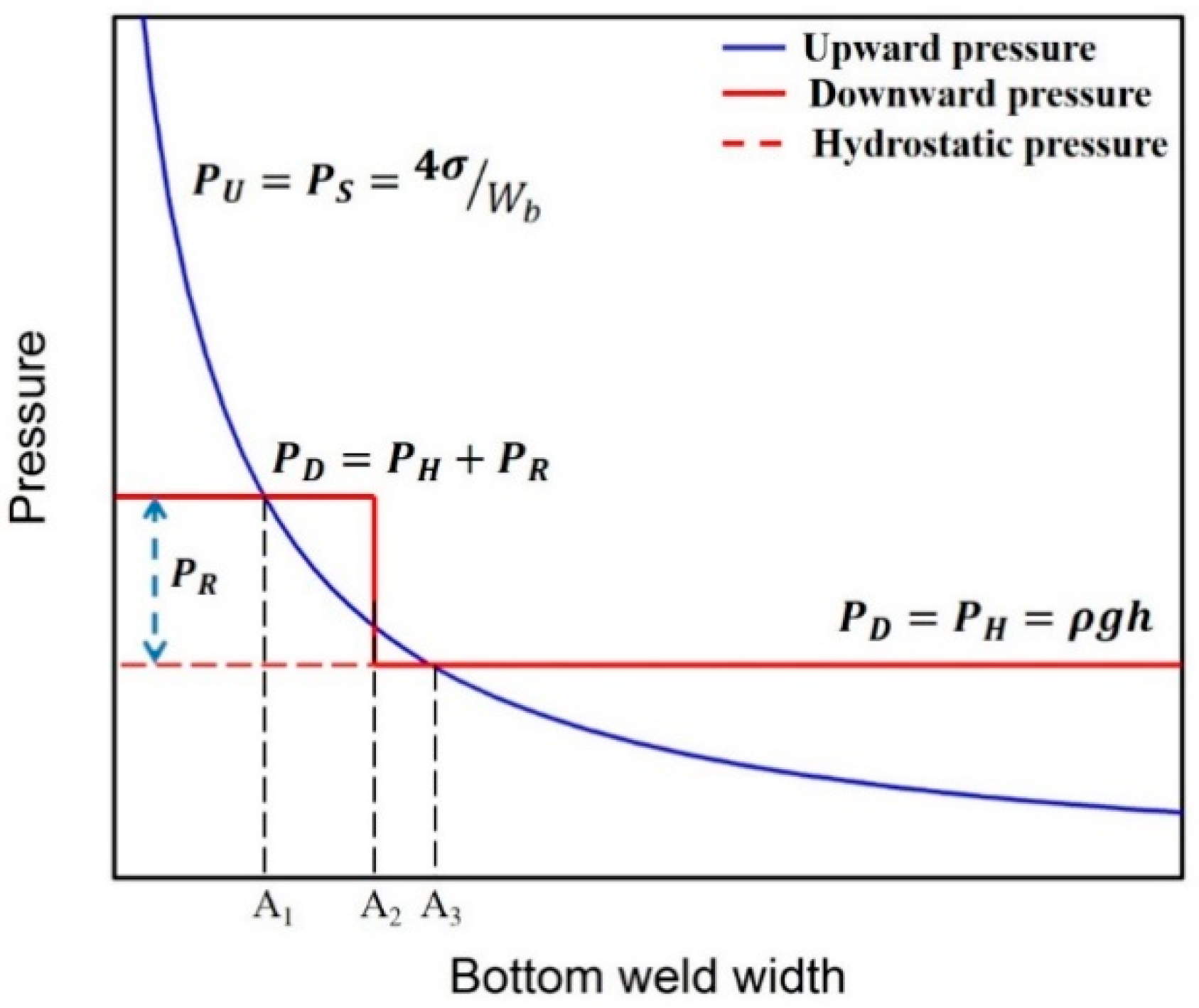
3.3. Formation Mechanism of Weld-Root Defects
4. Conclusions
- (1)
- With the increase of heat input from 300 J/mm to 1000 J/mm, four types of weld-root appearances—weld-root humping (30 mm/s), sound weld (25 mm/s), weld sagging (20 mm/s), and excessive weld sagging—were observed sequentially in high-power full-penetration of thick plate;
- (2)
- The keyhole exits at the bottom side were observed to stay open during the whole welding process for conditions of sound weld and weld sagging, while in the condition of weld-root humping, the keyhole exit at the bottom side closed and opened periodically;
- (3)
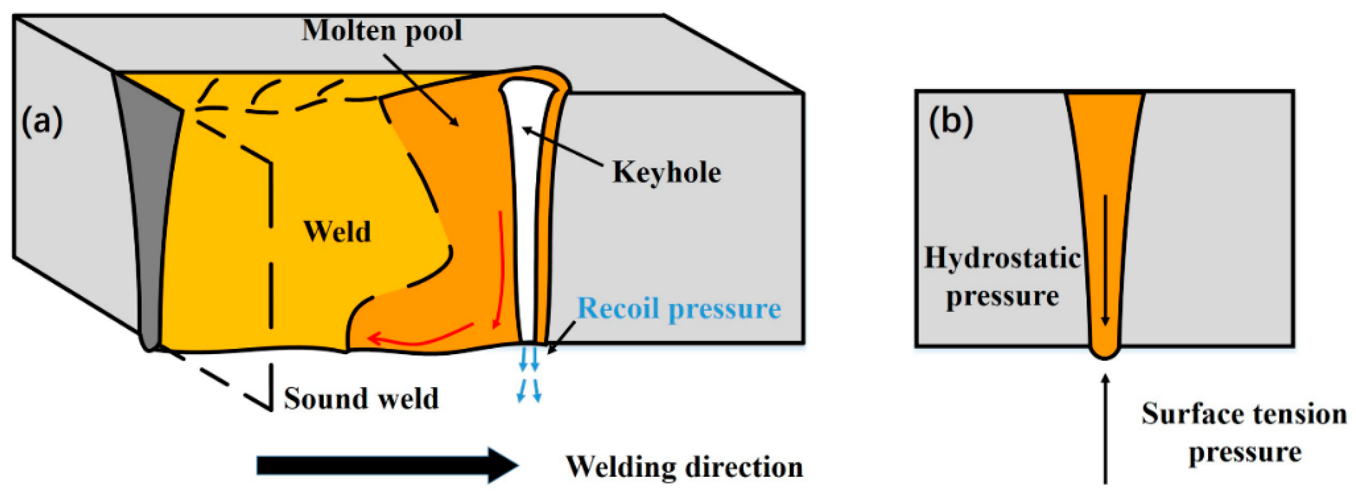
- Weld-root humping was formed due to the quasi-full-penetration keyhole. Weld sagging resulted from the imbalance of the hydrostatic pressure and surface tension in the condition of a through keyhole. When a weld-root sag is formed, increasing weld speed is the most effective method to obtain a narrower weld bead;
- (4)
- The state of the keyhole and weld geometry were the major factor that affects weld-root defects. The strategy of adjusting welding parameters should be determined according to the type of weld-root defect.
Author Contributions
Funding
Institutional Review Board Statement
Informed Consent Statement
Data Availability Statement
Acknowledgments
Conflicts of Interest
Nomenclature
| Abbreviations/symbols/letters | Meaning |
| CW | Continuous Wave |
| P | Laser power |
| V | Welding Speed |
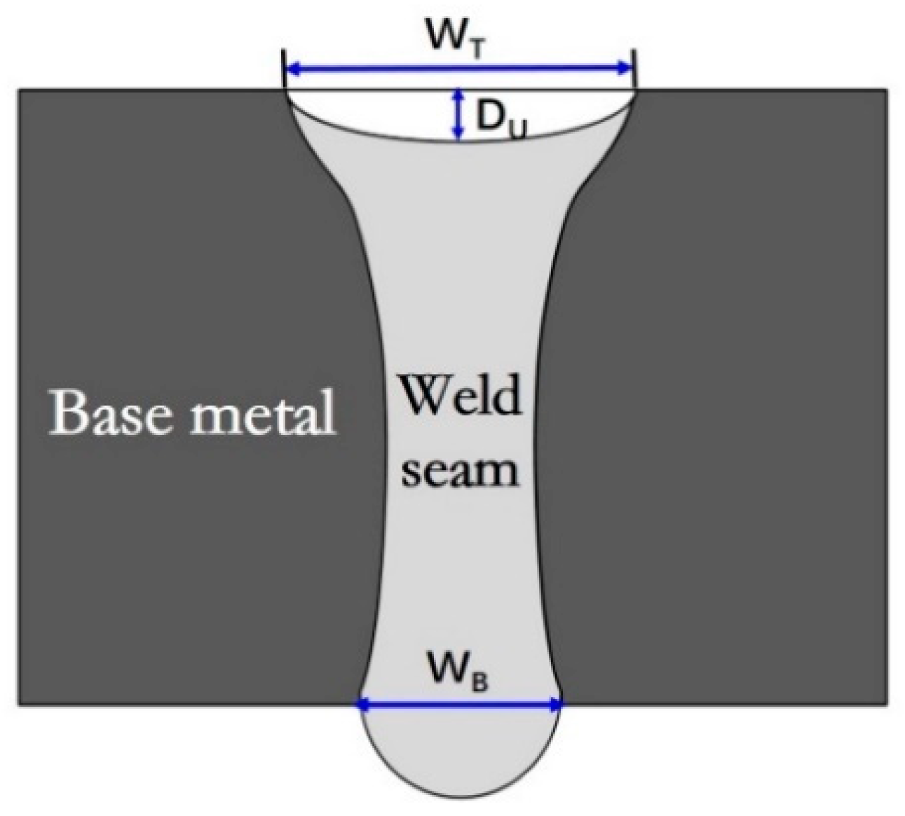
| Wt | The top weld width |
| Du | The underfilling depth |
| Wb | The bottom weld width |
| σ | Surface tension coefficient |
| α | Contact angle of the solid-liquid interface |
| ρ | Density of the liquid melt |
| g | Gravitational acceleration |
| h | Plate thickness |
References
- El-Batahgy, A.M.; Klimova-Korsmik, O.; Akhmetov, A.; Turichin, G. High-Power Fiber Laser Welding of High-Strength AA7075-T6 Aluminum Alloy Welds for Mechanical Properties Research. Materials 2021, 14, 7498. [Google Scholar] [CrossRef] [PubMed]
- Jiang, M.; Jiang, N.; Chen, X.; Ma, S.; Chen, Y.; Chen, Y.; Lei, Z. Experimental and numerical investigation of single-pass laser welding of 20 mm-thick high-strength steel under reduced ambient pressure. J. Mater. Res. Technol. 2021, 15, 2317–2331. [Google Scholar] [CrossRef]
- Wang, G.; Wang, J.; Yin, L.; Hu, H.; Yao, Z. Quantitative correlation between thermal cycling and the microstructures of X100 pipeline steel laser-welded joints. Materials 2020, 13, 121. [Google Scholar] [CrossRef] [PubMed] [Green Version]
- Jiang, M.; Tao, W.; Chen, Y.; Li, F. Comparison of processing window in full penetration laser welding of thick high-strength steel under atmosphere and sub-atmosphere. Opt. Laser Technol. 2019, 109, 449–455. [Google Scholar] [CrossRef]
- Vollertsen, F.; Thomy, C. Welding with Fiber Lasers From 200 To 17000 W. In International Congress on Applications of Lasers & Electro-Optics; ICALEO: Miami, FL, USA, 2005; pp. 23–27. [Google Scholar]
- Grupp, M.; Klinker, K.; Cattaneo, S. Welding of high thicknesses using a fibre optic laser up to 30 kW. Weld Int. 2013, 27, 109–112. [Google Scholar] [CrossRef]
- Kawahito, Y.; Mizutani, M.; Katayama, S. High quality welding of stainless steel with 10 kW high power fibre laser. Sci. Technol. Weld Join 2009, 14, 288–294. [Google Scholar] [CrossRef]
- Kawahito, Y.; Terajima, T.; Kimura, H.; Kuroda, T.; Nakata, K.; Katayama, S.; Inoue, A. High-power fiber laser welding and its application to metallic glass Zr55Al10Ni5Cu30. Mater. Sci. Eng. B 2008, 148, 105–109. [Google Scholar] [CrossRef]
- Kawahito, Y.; Matsumoto, N.; Abe, Y.; Katayama, S. Laser absorption characteristics in high-power fibre laser welding of stainless steel. Weld Int. 2013, 27, 129–135. [Google Scholar] [CrossRef]
- Kaplan, A.F.H.; Wiklund, G. Advanced welding analysis methods applied to heavy section welding with a 15 kW fiber laser. In Welding in the World; IIW: Singapore, 2009; pp. 295–300. [Google Scholar]
- Zhang, M.; Chen, G.; Zhou, Y.; Liao, S. Optimization of deep penetration laser welding of thick stainless steel with a 10 kW fiber laser. Mater. Des. 2014, 53, 568–576. [Google Scholar] [CrossRef]
- Zhang, M.; Zhang, Z.; Tang, K.; Mao, C.; Hu, Y.; Chen, G. Analysis of mechanisms of underfill in full penetration laser welding of thick stainless steel with a 10 kW fiber laser. Opt. Laser Technol. 2018, 98, 97–105. [Google Scholar] [CrossRef]
- Shen, X.; Li, L.; Guo, W.; Teng, W.; He, W. Comparison of processing window and porosity distribution in laser welding of 10 mm thick 30CrMnSiA ultrahigh strength between flat (1G) and horizontal (2G) positions. J. Laser Appl. 2016, 28, 022418. [Google Scholar] [CrossRef]
- Frostevarg, J.; Haeussermann, T. Dropout formation in thick steel plates during laser welding Dropout formation in thick steel plates during laser welding. In Proceedings of the IIW International Conference on High Strength Materials–Challenges and Applications, Helsinki, Finland, 2–3 July 2015. [Google Scholar]
- Bachmann, M.; Gumenyuk, A.; Rethmeier, M. Welding with High-power Lasers: Trends and Developments. Phys. Procedia 2016, 83, 15–25. [Google Scholar] [CrossRef]
- Pan, Q.; Mizutani, M.; Kawahito, Y.; Katayama, S. High power disk laser-metal active gas arc hybrid welding of thick high tensile strength steel plates. J. Laser Appl. 2016, 28, 012004. [Google Scholar] [CrossRef]
- Pan, Q.; Mizutani, M.; Kawahito, Y.; Katayama, S. Effect of shielding gas on laser–MAG arc hybrid welding results of thick high-tensile-strength steel plates. Weld World 2016, 60, 653–664. [Google Scholar] [CrossRef]
- Blecher, J.J.; Palmer, T.A.; DebRoy, T. Mitigation of root defect in laser and hybrid laser-arc welding. Weld. J. 2015, 94, 73–82. [Google Scholar]
- Jiang, M.; Chen, X.; Chen, Y.; Tao, W. Mitigation of porosity defects in fiber laser welding under low vacuum. J. Mater. Process. Technol. 2020, 276, 116385. [Google Scholar] [CrossRef]
- Matsunawa, A.; Kim, J.-D.; Seto, N.; Mizutani, M.; Katayama, S. Dynamics of keyhole and molten pool in laser welding. J. Laser Appl. 1998, 10, 247. [Google Scholar] [CrossRef]
- Jiang, M.; Chen, X.; Chen, Y.; Tao, W. Increasing keyhole stability of fiber laser welding under reduced ambient pressure. J. Mater. Process. Technol. 2019, 268, 213–222. [Google Scholar] [CrossRef]
- Rai, R.; Burgardt, P.; Milewski, J.O.; Lienert, T.J.; DebRoy, T. Heat transfer and fluid flow during electron beam welding of 21Cr–6Ni–9Mn steel and Ti–6Al–4V alloy. J. Phys. D Appl. Phys. 2009, 42, 025503. [Google Scholar] [CrossRef]
- Zhang, L.J.; Zhang, J.X.; Gumenyuk, A.; Rethmeier, M.; Na, S.J. Numerical simulation of full penetration laser welding of thick steel plate with high power high brightness laser. J. Mater. Process. Technol. 2014, 214, 1710–1720. [Google Scholar] [CrossRef]
- Avilov, V.V.; Gumenyuk, A.; Lammers, M.; Rethmeier, M. PA position full penetration high power laser beam welding of up to 30 mm thick AlMg3 plates using electromagnetic weld pool support. Sci. Technol. Weld Join 2012, 17, 128–133. [Google Scholar] [CrossRef]


| Element | Mn | C | Si | S | P | Ni | Nb | Mo | Cr | Ti | Fe |
|---|---|---|---|---|---|---|---|---|---|---|---|
| Content | 1.28 | 0.16 | 0.26 | 0.003 | 0.007 | 0.02 | 0.027 | 0.13 | 0.19 | 0.018 | Bal. |
Publisher’s Note: MDPI stays neutral with regard to jurisdictional claims in published maps and institutional affiliations. |
© 2022 by the authors. Licensee MDPI, Basel, Switzerland. This article is an open access article distributed under the terms and conditions of the Creative Commons Attribution (CC BY) license (https://creativecommons.org/licenses/by/4.0/).
Share and Cite
Zhang, H.; Jiang, M.; Chen, X.; Wei, L.; Wang, S.; Jiang, Y.; Jiang, N.; Wang, Z.; Lei, Z.; Chen, Y. Investigation of Weld Root Defects in High-Power Full-Penetration Laser Welding of High-Strength Steel. Materials 2022, 15, 1095. https://doi.org/10.3390/ma15031095
Zhang H, Jiang M, Chen X, Wei L, Wang S, Jiang Y, Jiang N, Wang Z, Lei Z, Chen Y. Investigation of Weld Root Defects in High-Power Full-Penetration Laser Welding of High-Strength Steel. Materials. 2022; 15(3):1095. https://doi.org/10.3390/ma15031095
Chicago/Turabian StyleZhang, Hengquan, Meng Jiang, Xi Chen, Lianfeng Wei, Shizhong Wang, Yumo Jiang, Nan Jiang, Zhiyuan Wang, Zhenglong Lei, and Yanbin Chen. 2022. "Investigation of Weld Root Defects in High-Power Full-Penetration Laser Welding of High-Strength Steel" Materials 15, no. 3: 1095. https://doi.org/10.3390/ma15031095
APA StyleZhang, H., Jiang, M., Chen, X., Wei, L., Wang, S., Jiang, Y., Jiang, N., Wang, Z., Lei, Z., & Chen, Y. (2022). Investigation of Weld Root Defects in High-Power Full-Penetration Laser Welding of High-Strength Steel. Materials, 15(3), 1095. https://doi.org/10.3390/ma15031095