Article

Characterization of a Magnesium Fluoride Conversion Coating on Mg-2Y-1Mn-1Zn Screws for Biomedical Applications

1
National Research Council, Institute of Condensed Matter Chemistry and Technologies for Energy, CNR-ICMATE, 16149 Genoa, Italy
2
Biotrics Bioimplants AG, Ullsteinstrasse 108, 12109 Berlin, Germany
3
Prosthodontics, Geriatric Dentistry and Craniomandibular Disorders, Charité Universitätsmedizin Berlin, Aßmannshauser Straße 4–6, 14197 Berlin, Germany
4
Laboratory for Biomaterials and Bioengineering (CRC-I), Department of Min-Met-Materials Engineering and University Hospital Research Center, Regenerative Medicine, Laval University, Quebec City, QC G1V 0A6, Canada
*
Authors to whom correspondence should be addressed.
Materials 2022, 15(22), 8245; https://doi.org/10.3390/ma15228245
Submission received: 4 October 2022 / Revised: 12 November 2022 / Accepted: 17 November 2022 / Published: 20 November 2022
(This article belongs to the Special Issue Research and Development of New Metal-Based Biomaterials)

Abstract

:
MgF2-coated screws made of a Mg-2Y-1Mn-1Zn alloy, called NOVAMag® fixation screws (biotrics bioimplants AG), were tested in vitro for potential applications as biodegradable implants, and showed a controlled corrosion rate compared to non-coated screws. While previous studies regarding coated Mg-alloys have been carried out on flat sample surfaces, the present work focused on functional materials and final biomedical products. The substrates under study had a complex 3D geometry and a nearly cylindrical-shaped shaft. The corrosion rate of the samples was investigated using an electrochemical setup, especially adjusted to evaluate these types of samples, and thus, helped to improve an already patented coating process. A MgF2/MgO coating in the µm-range was characterized for the first time using complementary techniques. The coated screws revealed a smoother surface than the non-coated ones. Although the cross-section analysis revealed some fissures in the coating structure, the electrochemical studies using Hanks’ salt solution demonstrated the effective role of MgF2 in retarding the alloy degradation during the initial stages of corrosion up to 24 h. The values of polarization resistance (Rp) of the coated samples extrapolated from the Nyquist plots were significantly higher than those of the non-coated samples, and impedance increased significantly over time. After 1200 s exposure, the Rp values were 1323 ± 144 Ω.cm2 for the coated samples and 1036 ± 198 Ω.cm2 for the non-coated samples, thus confirming a significant decrease in the degradation rate due to the MgF2 layer. The corrosion rates varied from 0.49 mm/y, at the beginning of the experiment, to 0.26 mm/y after 1200 s, and decreased further to 0.01 mm/y after 24 h. These results demonstrated the effectiveness of the applied MgF2 film in slowing down the corrosion of the bulk material, allowing the magnesium-alloy screws to be competitive as dental and orthopedic solutions for the biodegradable implants market.

1. Introduction

Magnesium-based alloys represent one of the most promising classes of biodegradable biomaterials to produce devices for both orthopedic and dental applications, providing appropriate temporary support while forming new bone [1]. Conventional metals in biomaterial applications, such as stainless steel, Ti-based alloys, and Nitinol, used to produce “permanent” implants, have superior mechanical properties than magnesium-based materials [2]. However, such metallic materials can give rise to allergic reactions, permanent physical irritation, chronic inflammatory local responses [3], and, most importantly, the need to be removed by a follow-up surgery after healing [1]. Magnesium-implants, on the other hand, can naturally degrade in a physiological environment without most of the aforementioned risks [1,4], representing a great alternative to Ti-implants when temporary support or bone regeneration are required. Magnesium is non-toxic and is even an essential element in the human body: it is involved in protein synthesis, activation of various enzymes, and regulation of activities in the neuromuscular and central nervous systems [1,5]. Magnesium also has advantages over other absorbable metals, such as iron and zinc, due to its recommended daily intake in adults (240–420 mg·day−1), which is around 50 times that of iron (8–18 mg·day−1) and zinc (8–11 mg·day−1) [6]. From the perspective of bone implantation, magnesium has the advantage of a Young’s modulus value (41–45 GPa) close to that of natural bone (3–20 GPa) [7] and excellent osteoconductivity [8]. Moreover, Mg ions have been shown to enhance the local release of a neuropeptide (CGRP) from sensory nerve endings in the periosteum. This stimulates the persisting periosteal stem cells to create cortical bone [9], and enhances the Wnt signaling pathway in hBMCs to stimulate cancellous bone growth [10]. In addition, the simultaneous change of oxygen concentration adjacent to corroding Mg implants and the local high Mg ion concentration promotes angiogenesis [11]. The major drawback of magnesium application resides in its fast and uncontrolled dissolution when immersed in physiological media containing chloride; pure magnesium (Mg = 99.9 wt.%; Fe < 40 ppm) has a high corrosion rate of 2.89 mm·year−1 in 0.9% NaCl solution [12]. The rapid degradation rate results in mechanical integrity loss [13,14] and hydrogen bubbles formation [15], which can delay bone healing [16], block blood flow, and significantly alter the local pH [17].
To control the magnesium degradation rate and improve its mechanical properties, the addition of alloying elements, forming solid solutions and secondary phases, or the use of special processing or surface modification routes is required [1,18,19]. One of the most common solutions to decrease the corrosion rate is to modify the material surface, a usually simpler and more practical approach than changing the bulk structure and composition [20,21]. Different types of coatings have already been developed for the application of magnesium-alloys, such as β-tricalcium phosphate [22], hydrogenated amorphous silicon [23], nanomembranes obtained by electrospinning [24], electrodeposited hydroxyapatite [25,26], calcium phosphate conversion [27], and magnesium fluoride [28], among others. These coatings can partially control material degradation. In particular, fluoride films have been shown to have higher resistance and lower capacitance than calcium phosphates, and were significantly more effective in delaying the degradation rate of the bulk [29,30]. In addition, fluorine is essential in the human diet and is required for normal dental and skeletal growth; it promotes osteoblast proliferation and increases new mineral deposition in cancellous bone naturally degrading in the human body [29]. The safety of MgF2 coatings has already been proven, considering its in vivo solubility and decomposition rate, as well as the fluoride average daily intake in the human diet [31]. Moreover, fluoride-coated magnesium-alloys showed a satisfying biocompatibility toward co-cultivated human smooth muscle and endothelial cells [32]. An extensive in vitro study on the biocompatibility of fluoride-surface-modified AZ31 Mg-alloy revealed a significant stimulation of cell proliferation and a strong enhancement of the mitochondrial respiratory activity when mouse osteoblasts (MC3T3-E1), fibroblasts (L929), and macrophages (J774) cell lines were cultured with the modified alloy [33]. Moreover, the positive effect of MgF2 coating in delaying the corrosion of the bulk material to a reasonable level was demonstrated in 2010; electrochemical and immersion tests showed an improved corrosion resistance of fluoride-coated AZ31B alloys in a simulated body compared to the bare Mg-alloy [34]. In 2013, this result was further confirmed and consolidated by experimental tests on a MgF2 layer, produced as a conversion coating in an HF bath, which showed an enhancement of the coated material corrosion resistance by increasing the acid concentration [35]. In the same year, it was found that a denser and more uniform MgF2 coating was formed on Mg-0.5Ca alloy surfaces by immersion in 40% HF compared to 35% HF-treated samples. Electrochemical results of those samples, obtained in Kokubo’s solution, revealed that the corrosion resistance of fluoride-coated samples was 30 times higher than the untreated ones [36]. An in vivo corrosion study on magnesium alloy LAE442 demonstrated the good corrosion protection of the fluoride layer after implantation of coated and non-coated cylinders into the medial femoral condyle of adult rabbits [37]. The MgF2 coating was no longer detected 4 weeks after implantation, and no subcutaneous gas cavities were found in any animals, proving a lower corrosion rate for the coated sample, as well as an adequate host response [37]. More recent studies, conducted in the past five years, have mainly focused on the biological characterization of the coating than on its impact on corrosion resistance. However, the reported findings confirm the positive impact of MgF2 towards decreasing corrosion of the bulk material [38], its biocompatibility [38,39,40], and its effect on promoting new bone formation [38,41]. They have also shown beneficial effects in terms of osteogenic differentiation of MC3T3-E1 cells and the vascularization of human umbilical vein endothelial cells (HUVECs) [42]. Table 1 summarizes the conclusions and the outcomes of the cited studies.
Most studies reported in the literature consisted of simple-shape, flat samples. In this work, however, a 3D and complex-shape material was coated with a MgF2 layer and studied. The aim was to evaluate the efficiency of the coating process in covering the screw in its entirety, and in decreasing the degradation of the bulk material.
In the present work, a MgF2 conversion coating was applied through a wet-chemical process on commercial Mg alloys, WZM211 or Mg-2Y-1Zn-1Mn, developed and patented by biotrics bioimplants AG. The purpose of the surface modification technique was to control the corrosion rate of biodegradable dental devices (screws) used in clinical procedures, known as Guided Bone Regeneration (GBR) [43,44]. Degradation of WZM211-coated alloys was investigated during in vitro and in vivo tests. Results revealed that the screw was slowly and completely resorbed after 52 weeks, thus providing adequate fixation in the early critical healing phase [37]. The magnesium fixation screw demonstrated all the key properties required for an ideal temporary fixation screw of membranes used in GBR surgeries [44,45]. Therefore, a characterization study of these materials and their degradation mechanism could allow the tuning of coating properties, making the screws more versatile in terms of performance. For this reason, a deep material characterization including SEM-EDS, AFM, and XPS analyses was proposed. In particular, the corrosion behavior of non-coated and coated screws was evaluated and compared in vitro in artificial physiological fluid using electrochemical techniques. The biological evaluation of these screws has been already carried out by biotrics bioimplants AG in a previous work [44].

2. Materials and Methods

2.1. Materials and Coating Process

NOVAMag® fixation screws (length L = ~13.5 mm; thread diameter Ø = ~1.2 mm), produced by biotrics bioimplants AG, were used as substrate materials. The nominal composition of the alloy, named WZM211, is reported in Table 2.
MgF2 conversion coating uses the principle of magnesium dissolution and interaction of its ions with fluoride ions, leading to the precipitation of MgF2 on the surface of the substrate, while hydrogen evolution takes place. The coating can be produced by immersion, the major safety concern in the use and disposal of fluoride-containing baths. The screws were first cleaned in an isopropanol bath for 20 min and then dried; they were then immersed in a 40% HF solution maintained at room temperature (T = 25 °C) and agitated. After this period of immersion, screws were extracted with a plastic sieve, cleaned in isopropanol, and then dried again. More details about this immersion process are reported in the botiss biomaterials AG patents [46]; work on the biological response of these treated Mg-alloys has been recently published [44]. Machined and treated WZM211 screws are here referred to as non-coated and MgF2-coated samples, respectively.

2.2. Samples Characterization

The morphology and homogeneity of coated and non-coated screw surfaces were evaluated by SEM-EDS (FEI Quanta250 SEM system (Thermo-Fisher, OR, USA)). The cross-section composition of the coated screws was further characterized using a focused ion beam and EDX (model 8530F). The acceleration voltage used was in the range of 10–20 kV. The topography and roughness of the surface were investigated by Atomic Force Microscopy (AFM, Dimension™ 3100, Digital Instrument, CA, USA) in tapping mode with an etched silicon tip (model NCHV, tip radius = 10 nm, Bruker). The chemical composition in the uppermost 5–10 nm of the surface was quantitatively investigated using X-ray photoelectron spectroscopy (XPS) (PHI 5600-ci, Physical Electronics, Chanhassen, MN, USA); the analyses were carried out using an incident angle of 45° with respect to the normal angle of the surface, and a residual pressure of 3 × 10⁻⁹ Torr. A survey spectrum, covering the range of 0–1400 eV, was first recorded using a standard achromatic aluminum Kα X-ray source (1488.6 eV) at 200 W. High-resolution spectra of C1s, O1s, Mg2s, and F1s regions were recorded with a magnesium Kα X-ray source (1253.6 eV) at 150 W. No charge neutralization was required. Curves fitting was determined by means of the least-squares method using PHI MultiPakTM software and Gaussian-Lorentz (30–70) functions with a Shirley background. The in vitro corrosion testing of the coatings using electrochemical experiments was conducted using a three-electrode mini-cell system, MCS (Ibendorf & Co. GmbH, Bernau bei Berlin, Germany), that tests complex surfaces without any additional preparation, and which has been previously used to study Mg-alloys [47]. A scheme of the MCS setup is shown in Figure 1.
The setup was composed of: (1) a plastic tip filled with the testing solution and in contact with the sample surface; (2) a tube, containing (3) a saturated calomel (SCE) as a reference electrode, and (4) a platinum counter-electrode; (5) a working electrode, which is the sample surface to be analyzed. Electric contact was achieved using a conductive copper adhesive stripe on the sample backside and a clamp, to ensure a good contact among the components. A digital microscope (Keyence VHX 900, Keyence Deutschland GmbH, Neu-Isenburg, Germany) was used, with a magnification 200×, to determine the area of the corrosion test spot. The tip and the tube of MCS were filled with 3 mL of Hanks’ buffered saline solution (HBSS, Thermofisher product number 14175095). The experiments were performed at room temperature (25 ± 1 °C). The tip of the MCS was placed directly on the surface of the specimen, analyzing 0.4 mm2 of its surface in each test; the electrochemical measurements started as soon as the tip had contact with the surface. The experiments were driven by a potentiostat (Autolab PGStat 302, Metrohm AG, Herisau, Switzerland), with frequency response analysis (FRA) software (Nova 2.0) connected to the electrochemical setup. Electrochemical impedance spectroscopy (EIS) tests were performed between 100 kHz and 10 mHz, at a potential amplitude of 10 mV around the OCP. The OCP was registered during the initial 20 s for stabilization, before starting EIS. Measurements were performed at 20 and 1200 s exposure of the surface to the medium. The EIS measurements are only possible on such a short time scale due to the small dimensions of the tip, in the range of 700 µm diameter. In order to investigate if the coating was stable upon prolonged exposure, single EIS experiments were performed up to a period of 24 h. After finishing the test, the sample was dried using pressured air and stored in controlled environmental conditions. Based on ASTM G102, the corrosion rate was defined by:
CR =   K 1 i corr   . W n   .   ρ  
where CR is the degradation rate (mm/yr); K1 = 3.27 × 10⁻³ mm·g·µA−1·cm−1·yr−1 is a conversion factor; icorr represents the corrosion current density (A); ρ stands for the density of the metal (g/cm3); W and n refer to the atomic weight (g) of the element and its valence, respectively. To determine the corrosion current density, the Stern approximation was used, an alternative approach to calculate this parameter from electrochemical data [48]:
i corr = R   .   T n .   F . Rp  
where R is the universal gas constant (8314 J/mol K), T represents the temperature (K), and Rp the polarization resistance (Ω.cm2).
The polarization resistance (Rp) was determined directly from the EIS curves at the limit where the imaginary part of the impedance reaches zero, as reported in the literature [49]; but in this case, only using the high-medium range frequencies, as the signal response in such a fast-changing surface is not linear in the low-frequency region [50]. The limitation of this approach is that the Rp values determined are only valid within the timescale of the experiment. However, it allows an analysis of reactive samples in a relatively short time frame (5–10 min), in a setup with a small sample area, such as the MCS. This obtains reproducible results. Validation of the results was made by fitting using an RC circuits model (ZView® for Windows, Scribner Associates Inc, Southern Pines, NC, USA).

3. Results and Discussion

3.1. Coating Morphology and Chemical Composition

Three different parts of the screw, consisting of the tip, thread, and flat head, were considered to evaluate the morphology and elemental distribution of the conversion coating over the entire material surface (see Figure 2 for further details). For non-coated screws, slightly different morphologies were found at the tip and head compared to the thread (Figure 2a–d). The latter showed, in fact, a finer structure with a minor amount of surface lines coming from the machining process. The machining lines and different morphologies could be associated to the parameters used in machining [51]. These different morphologies partially affected the final morphology of the HF-treated samples. It could be observed that a compact film, with the aspect of an amorphous layer, grew on the entire surface of treated samples (Figure 2e–h).
The mapping EDS analyses, as shown in Figure 3, revealed the presence of a mixed MgF2/MgO layer formed on the entire screw after immersion in HF. In the case of untreated screws, Mg was clearly visible after mapping (Figure 3b) and the amounts of Zn and Mn were close to nominal (1 wt.%), while the Y amount was lower and was always around 1 wt.% (Figure 4). This can be attributed to the fact that Y is not soluble in Mg, and it tends to accumulate and form precipitates, sometimes with Zn, so that it is concentrated in specific places in the alloy. The tip, thread, and head of the screws showed the same elemental distribution; therefore, only the results related to the screw head were selected. EDS elemental maps revealed a homogenous distribution of Mg, O, and F over the entire MgF2-coated screw surface; the alloying elements (Y, Zn and Mn) were not found at the sample surface as second phase particles due to their low amount and their distribution in solid solution inside the material bulk (Figure 5).
These elements did not segregate or form second phase compounds, visible in the micrometer range, on the surface of the coated screws. Few isolated particles of Y were found on coated samples (Figure 3e,k) [52]. EDS analysis conducted on coated surfaces confirmed the formation of a mixed MgO/MgF2 layer due to the presence of a significant amount of O and F (Figure 4).
The FIB and EDX analyses, conducted on the cross-section of coated samples, showed the presence of a thin interface zone between the substrate and the coating, without relevant diffusion. The coating thickness is not completely homogeneous, ranging from 1.8 to 2.4 µm (Figure 5a), filling the valleys of the surface, resulting in a smoother final surface. EDS spectrum and the related elemental compositions (Figure 5b,c) allowed to confirm the formation of the aforementioned mixed MgO/MgF2.
Moreover, some fissures were visible in the coating cross-section; they had mainly a vertical development that was perpendicular to the surface and to the substrate-coating interface. They were distributed all along the coating and some of them showed a length equal to the coating thickness. The distribution of the alloying elements over the cross-section confirmed the absence of Mn and Zn from the coating, while a small presence of Y particles (Figure 5i) was present. Mn was homogeneously distributed all over the alloy bulk (Figure 5g). Zn and Y were grouped in lamellar structures, dispersed in the alloy bulk. They formed some intermetallic compounds [53], visible in Figure 5h,i, and they were not affected by the process. Roughness measurements and topographical characterization were carried out on both non-coated and MgF2-coated screws (Figure 6). The roughness values (RMS and Ra) of non-coated screws appeared significantly higher than those of coated screws: RMS = 26.5 ± 4.2 nm and Ra = 14.3 ± 1.2 nm, respectively (Figure 6e). In addition, the topography of the samples changed as a result of the conversion coating treatment. The topography of coated screws, being smoother than that of non-coated screws, showed a regular texture, exhibiting the formation of grooves with a similar dimension and were homogeneously distributed (Figure 6a–d), as also reported by Makkar et al. [54].
XPS measurements were also performed to better evaluate and compare the chemical composition of both non-coated and MgF2-coated surfaces. Survey spectra of both surfaces, as well as their atomic concentrations, are reported in Figure 7.
The surface concentrations of Mg before and after the coating were approximately similar: ~35.1 at. % and ~36.7 at. %, respectively. As expected, coated samples showed a high amount of fluorine (37.3 at. %), while it was totally absent for non-coated samples (Figure 7b). The determined atomic concentrations of O1s on the non-coated and coated surfaces were ~44.1 at. % and ~6.3 at. %, respectively. From the surveys, it was not possible to confirm the presence of the previously mentioned MgO/MgF2 layer, as O, for example, it is often found for different kinds of Mg alloys [55,56,57]; Wan et al. found ~51.2 at. % of O on the surface of bare Mg alloy [55]. High-resolution spectra showed that surface chemical species were specific for the two conditions (Figure 8).
In particular, for the coated condition, the peaks of Mg2s, F1s, and O1s were shifted towards higher binding energy that could be related to a variation of the oxidation states on the surface (Figure 8). The deconvoluted C1s spectrum of coated samples showed a peak at ~ 284.1 eV, corresponding to the C-F bonds [58]. The O1s peaks revealed the presence of several species (Figure 8c,d). In particular, a variation was found between the two studied conditions; the binding energies of O1s peaks for non-coated and coated samples were ~529.7 eV and 531.9 eV, respectively. This shifted peak could be related not only to a change in the oxidation state, but also to the bonding between C and F atoms, which highly increased after the coating process. These shifted peaks resulted in the different binding energy for each component. The fit of the Mg2s peak of coated samples revealed the presence of three components at 88.9 eV (MgO), 90.1 eV (Mg(OH)2), and 91.4 eV (MgCO3). However, as indicated in Figure 8e,f, the location of each component differed from non-coated to coated samples. The high-resolution Mg2s spectra showed that non-coated samples possessed an additional peak located at a binding energy of ~89.0 eV, which was attributed to MgH2 [59]. Mg presents a strong tendency to bond with environmental molecules, and this results in the formation of hydroxides and carbonates on the surface [60]. As expected, the high-resolution F1s peaks corresponding to the non-coated condition showed no signal of fluorine. The fitted F1s peak for coated samples showed three peaks located at ~685.5 eV (MgF2), ~686.8 eV (C-F bonds), and ~688.0 eV (carbon fluorinated chains) [61]. The different characterization techniques used to evaluate the coating revealed the presence of a mixed MgO/MgF2 layer formed on the screw after immersion in HF, even if the F/Mg ratio detected by XPS analysis was sub-estimated (about 1.1). It was then proven that the treatment with HF led to a pronounced magnesium fluoride layer on the screws and significantly reduced the organic contamination, indicated by lower C and O contents on the surface. The formation of surface pores and the mixed nature of the coating could be explained by considering the micro-galvanic cells formed on the sample surface in contact with HF. In the micro-anode region, the magnesium could be dissolved as follows:
M g s M g a q 2 + + 2 e
Where the following cathodic reaction occurred:
2 H a q + + 2 e   H 2 g
Meanwhile, the metallic cations coming from the anodic reaction react with the fluoride anions of the solution, forming magnesium fluoride (5), and an oxidation reaction also occurred (6):
M g a q 2 + + 2 F a q   M g F 2 s
M g s + H 2 O l   M g O H 2 s + H 2 g
Since Mg(OH)2 was not stable in acidic solution [36], it forms other MgF2 and MgO:
M g O H 2 s + 2 H F a q   M g F 2 s + 2 H 2 O l
M g O H 2 s   M g O s + H 2 O l
The magnesium dissolution from the substrate and the consequent deposition of magnesium fluoride on the surface occurred with a dynamic balance. The reaction (5), occurring at substrate-medium interface, was gradually decreased by the fluoride formation; in fact, MgF2 was not soluble in water and acted as a diffusion barrier to ions migration. After an initial growth, MgF2 deposition was slowed down by the increasing thickness. After 12 h of immersion in HF, the barrier film was thick enough to terminate the reaction. The small pores detected on the coating surface could be caused by the H2(g) evolution that accompanied the formation of MgF2.

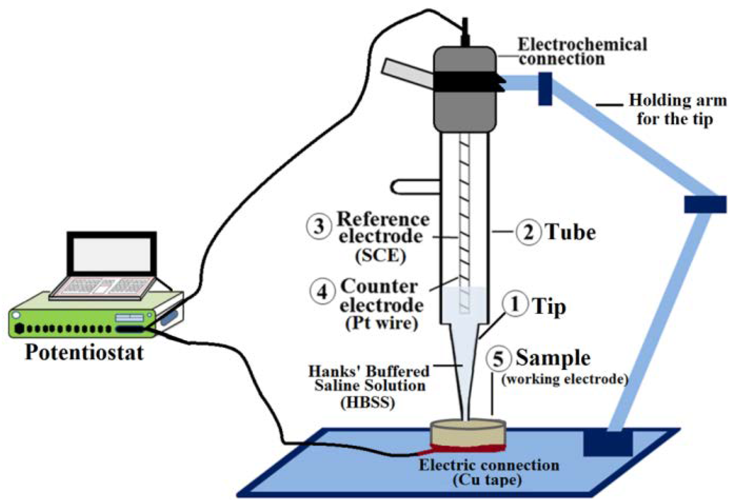
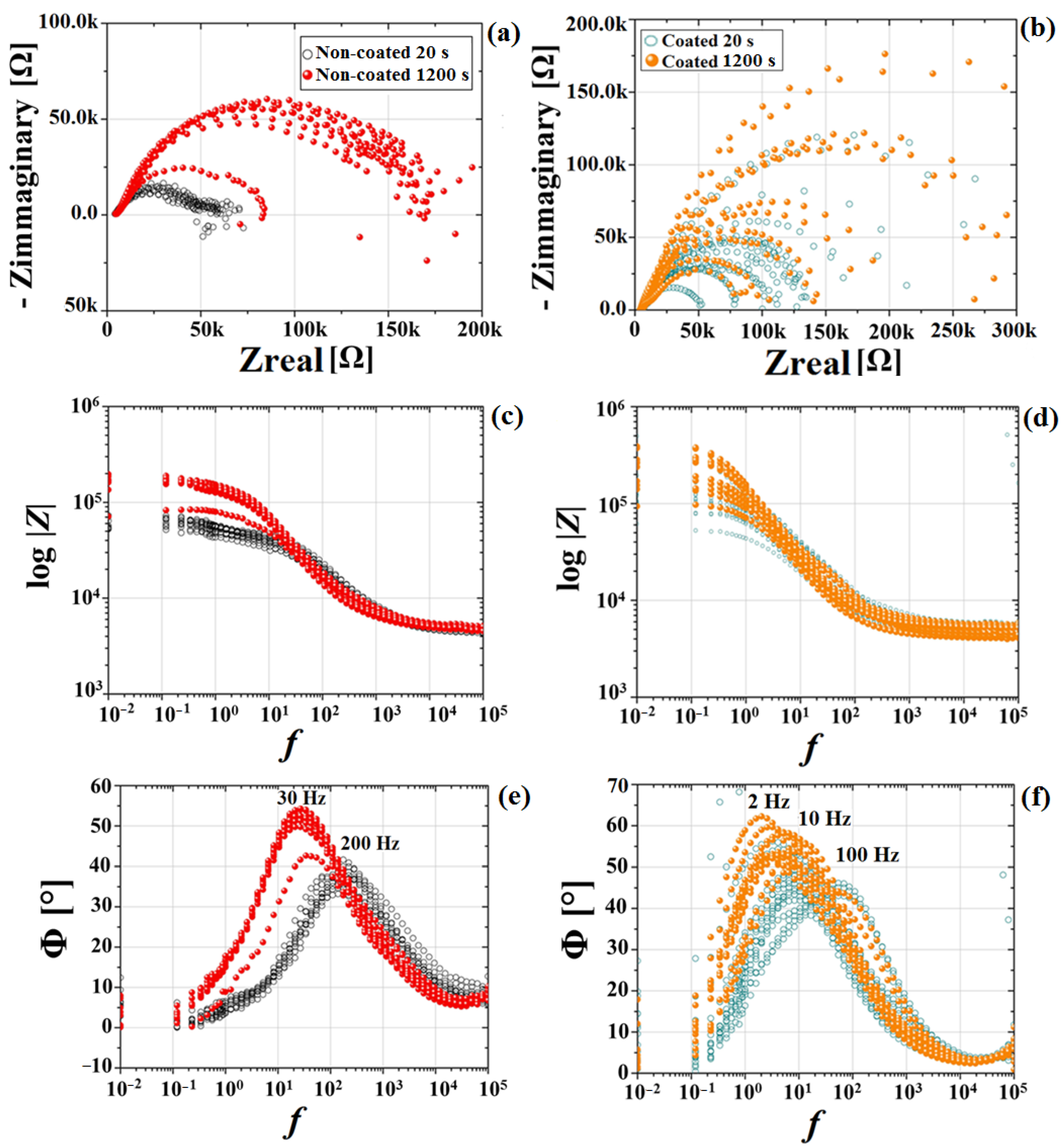
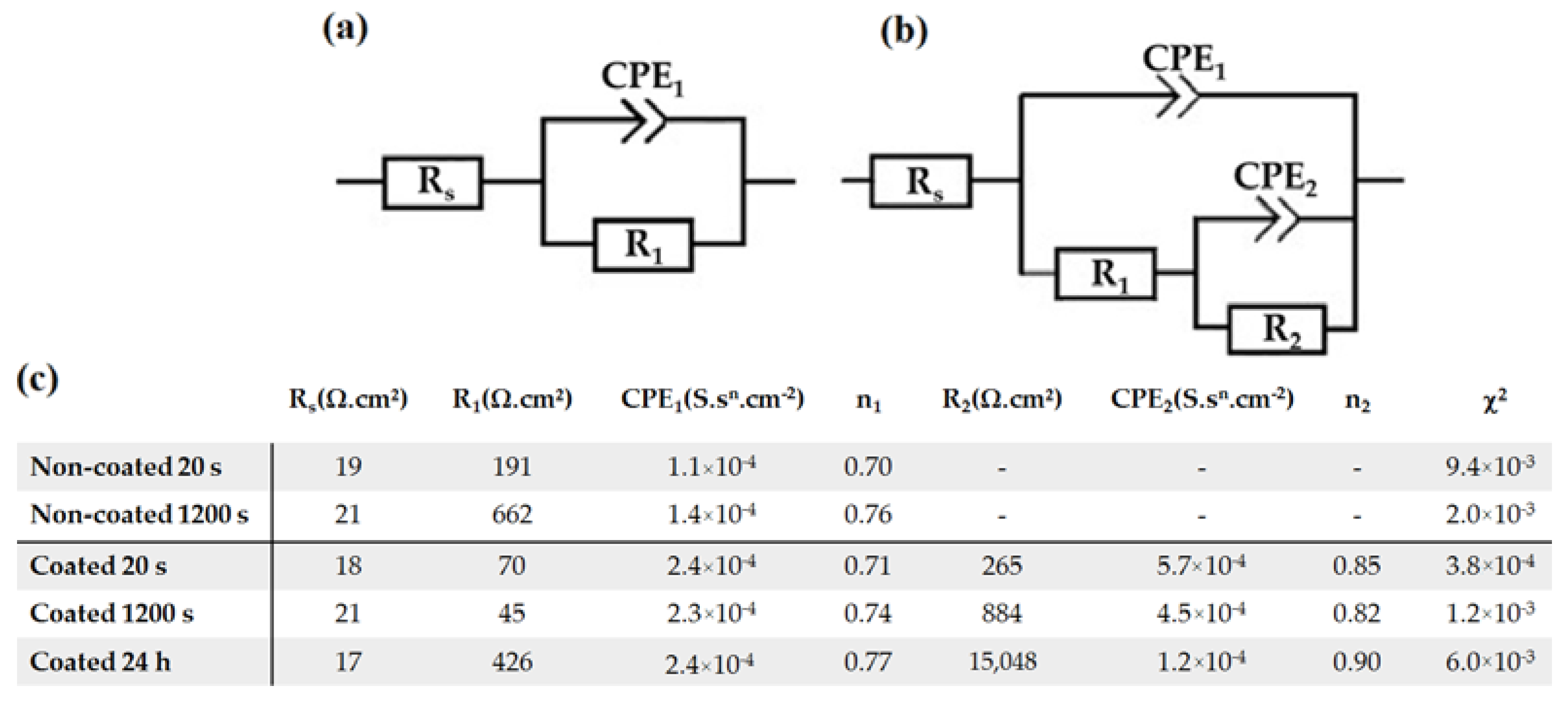
3.2. Electrochemical Results

The time-dependent corrosion behavior of non-coated and MgF2-coated Mg-alloys was evaluated and compared in terms of short exposure times. Nyquist and Bode plots after 20 and 1200 s of OCP are reported in Figure 9.
The uncoated samples exhibited only one capacitive loop, which represented the interface reaction between the electrolytic solution and the substrate, as already reported for Mg [62,63]. The phase angle had a peak at 200 Hz, which shifted over time until 30 Hz after 1200 s exposure to the electrolyte with a phase angle increase (Figure 9e). This behavior was attributed to the formation of an oxide layer on the sample surface and the slowing down of the corrosion process. For coated samples, the EIS plots consisted of two capacitive loops mostly overlapping, but with two distinctive characteristic frequencies in the in high (103 Hz) and medium (10 Hz) range frequency regions, indicating that two parallel processes occurred at the surface (Figure 9f). The high frequency capacitive loop represented the behavior of the coating-electrolyte interface, while the medium-range frequency capacitive loop was descriptive of the coating-substrate interface. Based on the extrapolation of the Nyquist plots, the values of polarization resistance (Rp), directly related to the corrosion resistance of the material, were obtained (Table 3). Initially, the Rp values of the coated samples were higher than those of the uncoated samples, confirming a significant decrease in the initial degradation rate due to the MgF2 layer, so that an improvement of the overall corrosion resistance of the studied magnesium alloy was registered.
The initial average corrosion rate of the coated samples, when compared to the uncoated alloy, decreased from 0.84 mm/y to 0.49 mm/y, as observed from the EIS results. Additionally, the coated samples did not show a significant statistical variation in polarization resistance between 20 s and 1200 s when in contact with the electrolyte (Figure 10).
In contrast, uncoated samples showed a considerable Rp variation when in contact with the electrolyte. This was also evident from the Bode phase graph, which showed a phase angle shift from 40 to 60° after 1200 s of exposure (Figure 9e), indicating an improvement in terms of corrosion resistance. This phenomenon, already observed and reported by Witte et al. and by Jamesh et al. [64,65], was related to the thickening of the corrosion product layer (usually Mg(OH)2), which acted as an effective barrier for the charge transfer process. The fitting of the EIS data using RC equivalent circuits could be satisfactorily achieved using the equivalent circuits represented by (Figure 11a,b), composed by Rs, the electrolyte resistance, R1 and CPE1, representing the surface resistance and capacitance of the double layer, respectively. The additional (R2 and CPE2) circuit components stand for the surface resistance and capacitance of the innermost part of the MgF2 coating [66,67]. Therefore, the Rp for the coated samples is represented by R1+R2. A constant phase element (CPE) was used instead of a pure capacitor. The CPE behavior is a form of distortion from an ideal electrical capacitor. It can be explained by local changes in the electrical field and in the potential of the surface, arising from surface heterogeneities and roughness [68]. The fitted electrical parameters, including the exponent “n” that indicates the deviation of the CPE from the ideal capacitive behavior, are shown in Figure 11c, and have been documented for magnesium alloys [50]. Analysis of the data shows that the film resistance (R1+R2) increased with exposure time, in particular for the samples coated with MgF2. Moreover, these results confirm that the film formed on the surface of Mg in buffered environments plays a protecting role for the substrate, as reported in [69]. Compared with this naturally formed film, the compactness and thickness of the MgF2 coating acts as a barrier against the corrosion process of Mg samples, significantly increasing the impedance, as shown in [41].
These results were further confirmed by the prolonged exposure test of the coated samples over a period of 24 h, as shown in Figure 12. The two capacitive arcs, also found for short exposure times, became more pronounced (Figure 12c). Moreover, there was a significant increase in the capacitive arc in the Nyquist plot over time, with the corrosion rate decreasing from 0.49 mm/y at the beginning of the experiment, to 0.01 mm/y after 24 h. This impedance increase could be related to the presence of corrosion products filling the micro-cavities through the coating and along the grain boundaries. The formation of corrosion products acted as a barrier between the electrolyte solution and the coated magnesium, resulting in the Rp growth and, consequently, a significant decrease of the corrosion rate, as reported in [49].

4. Conclusions

NOVAMag® fixation screws were characterized before and after a fluoride conversion treatment, and applied to the bare alloy with the intent to reduce the corrosion rate in the first hours of implantation in human bones. The following conclusions were determined:
(1)
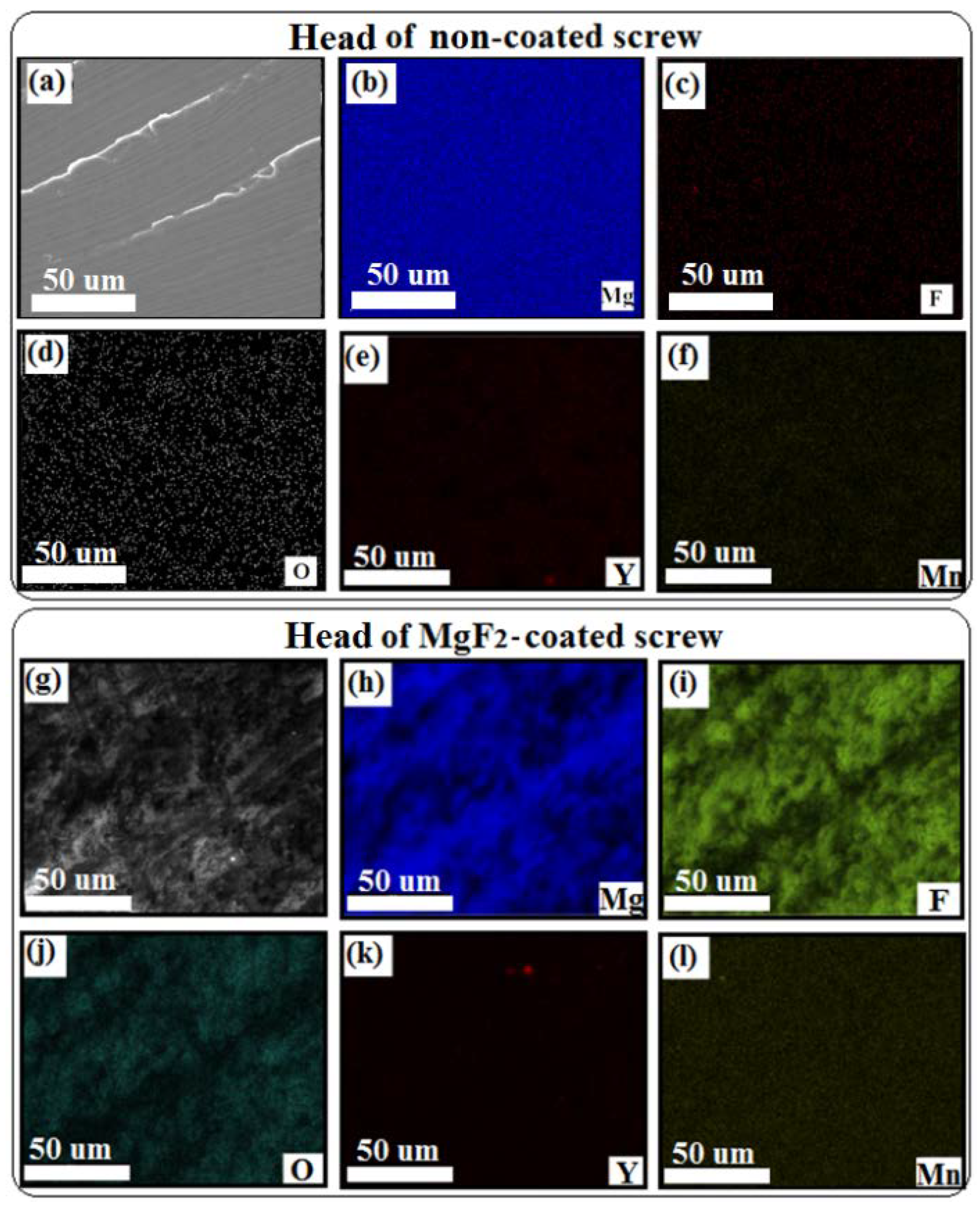
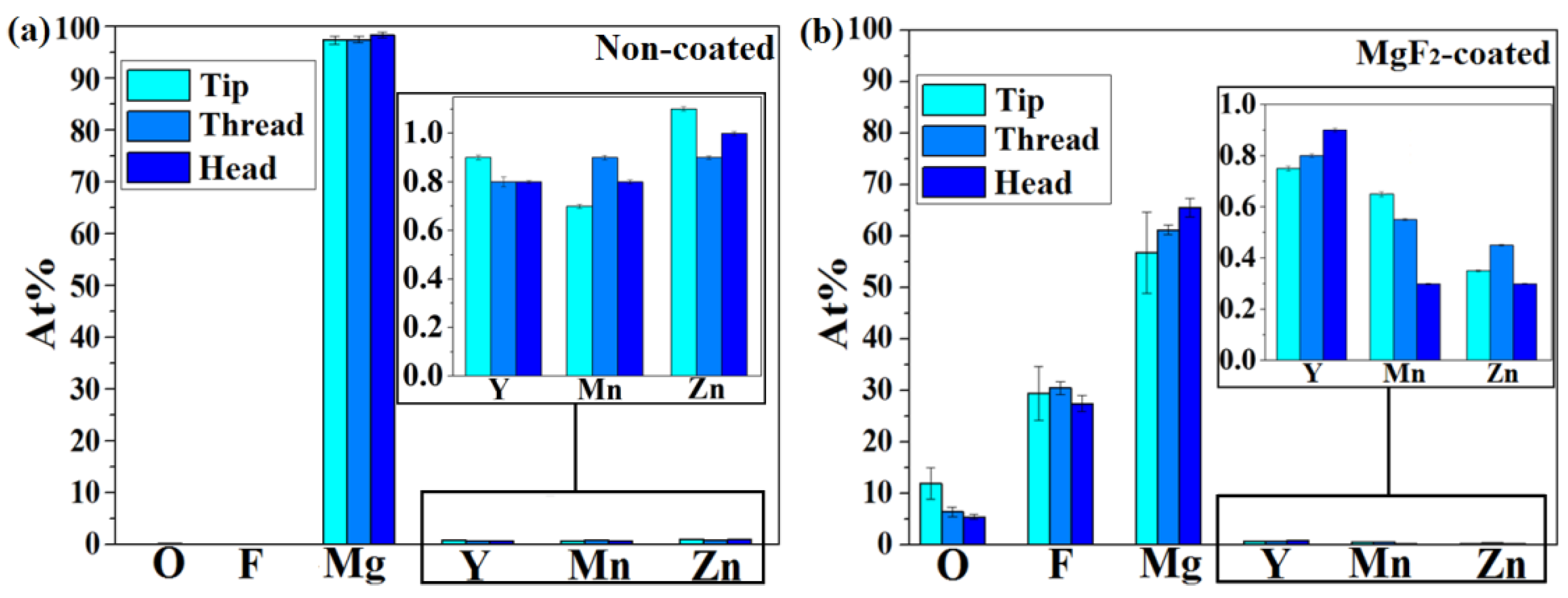
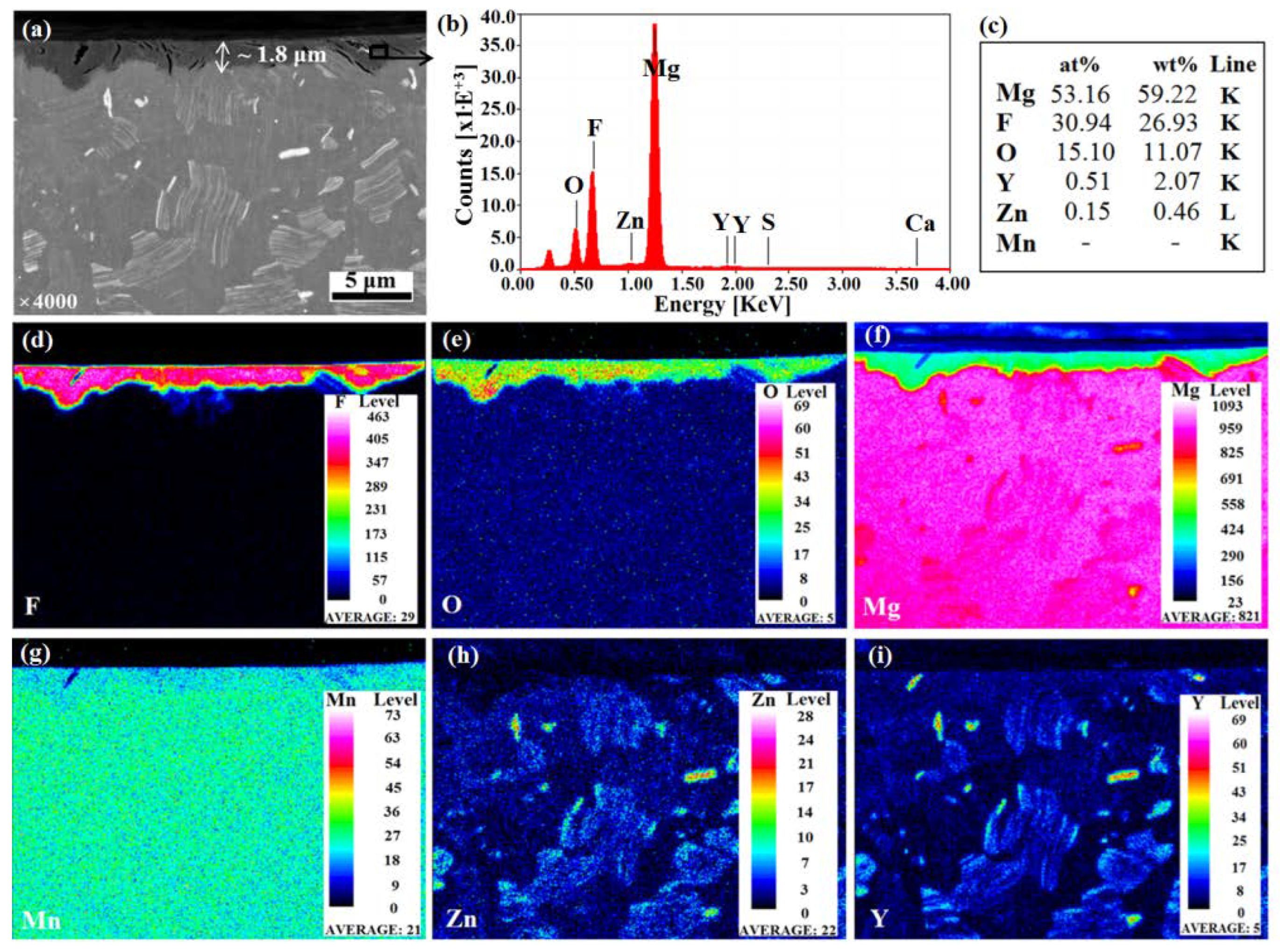
A successful formation of a mixed MgF2/MgO coating, about 2 µm thick, after immersion in HF, was obtained.
(2)
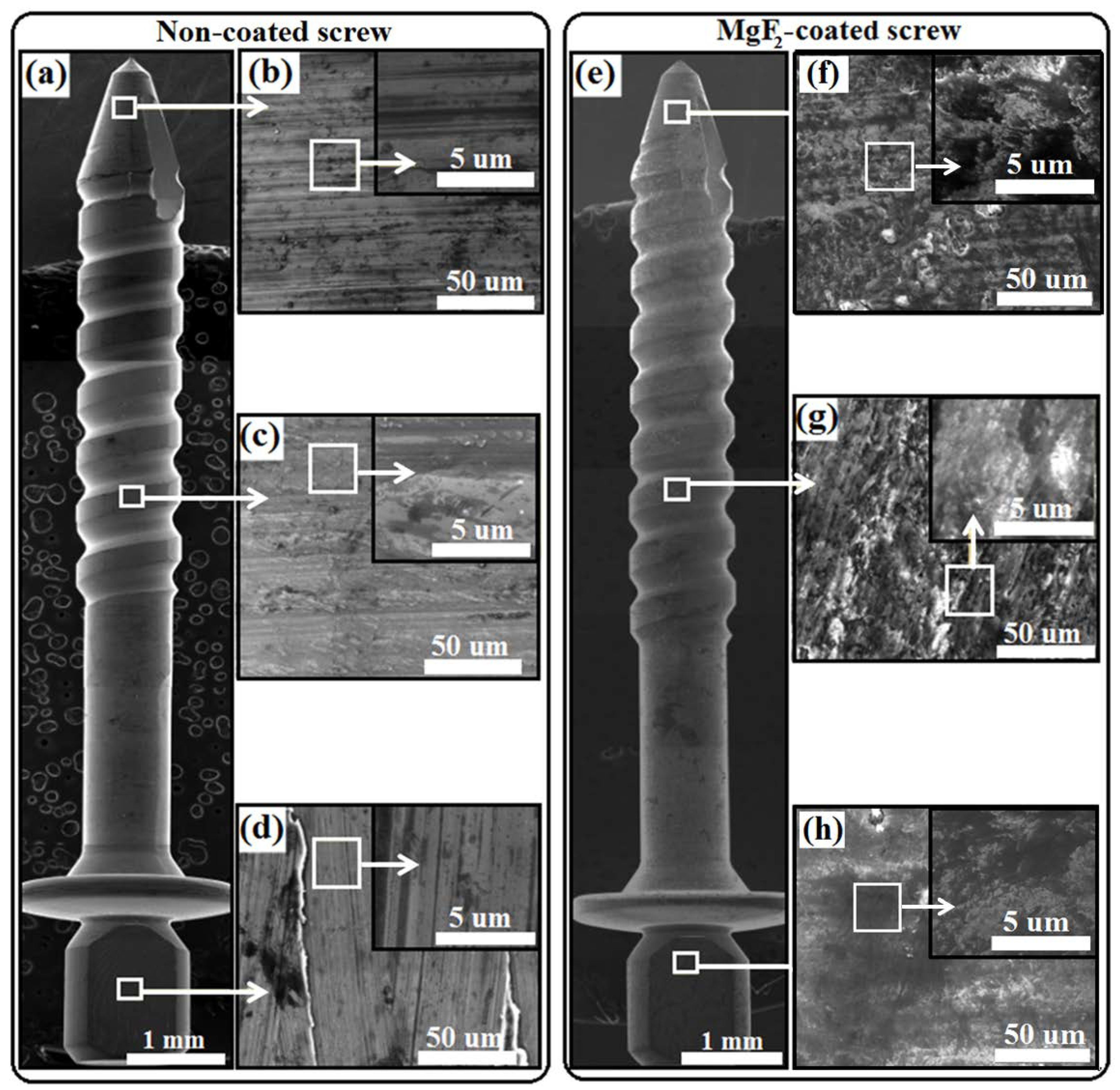
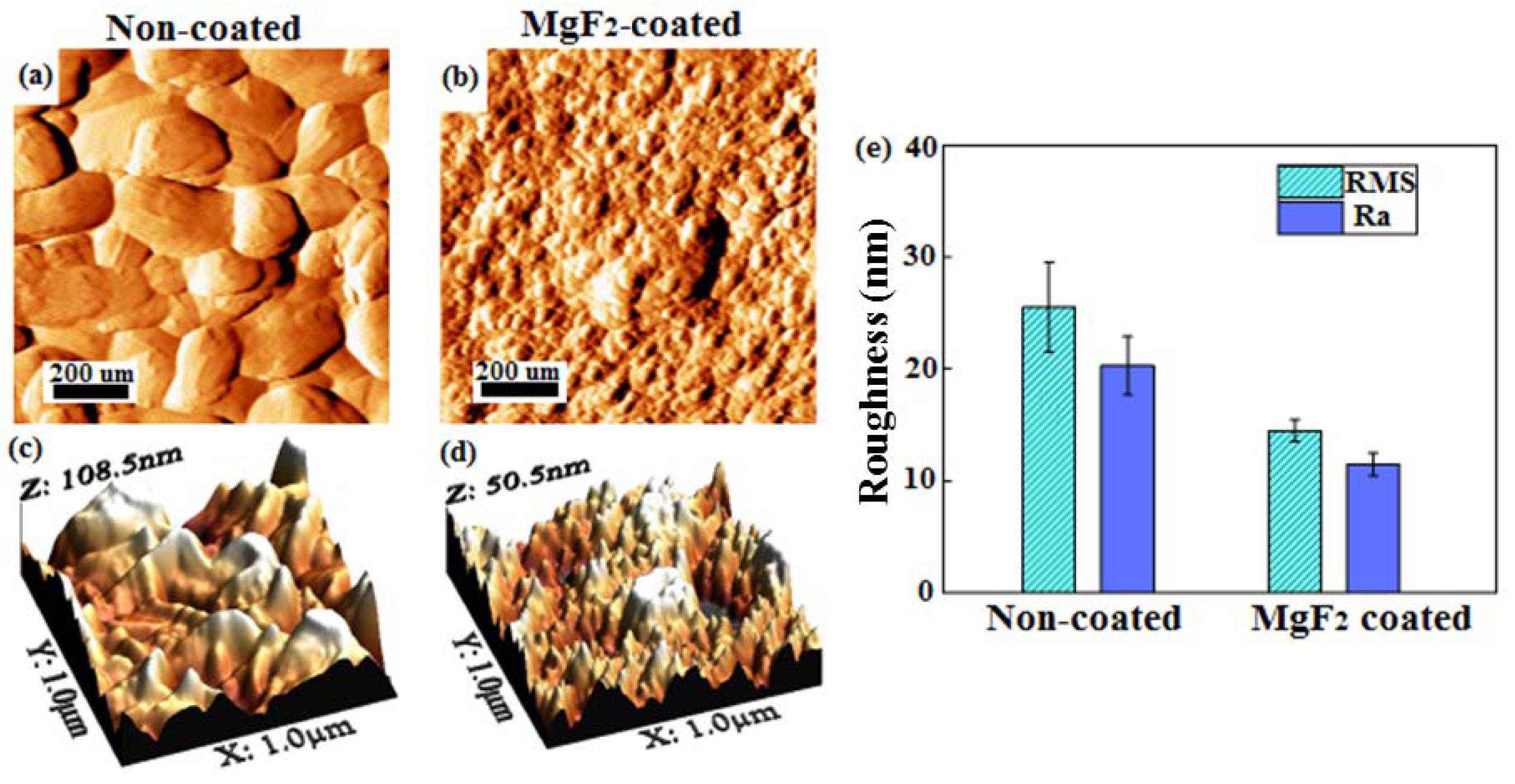
The topography of the coated screws, being smoother than that of the non-coated screws, showed homogenous features, exhibiting the formation of grooves with a more similar dimension and were evenly distributed.
(3)
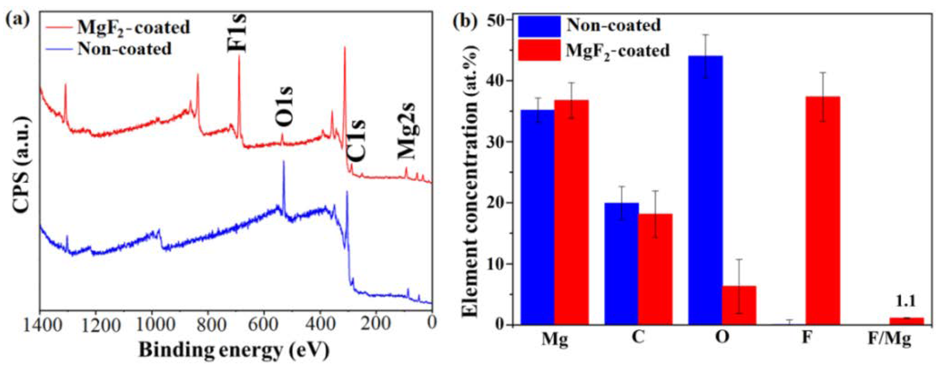
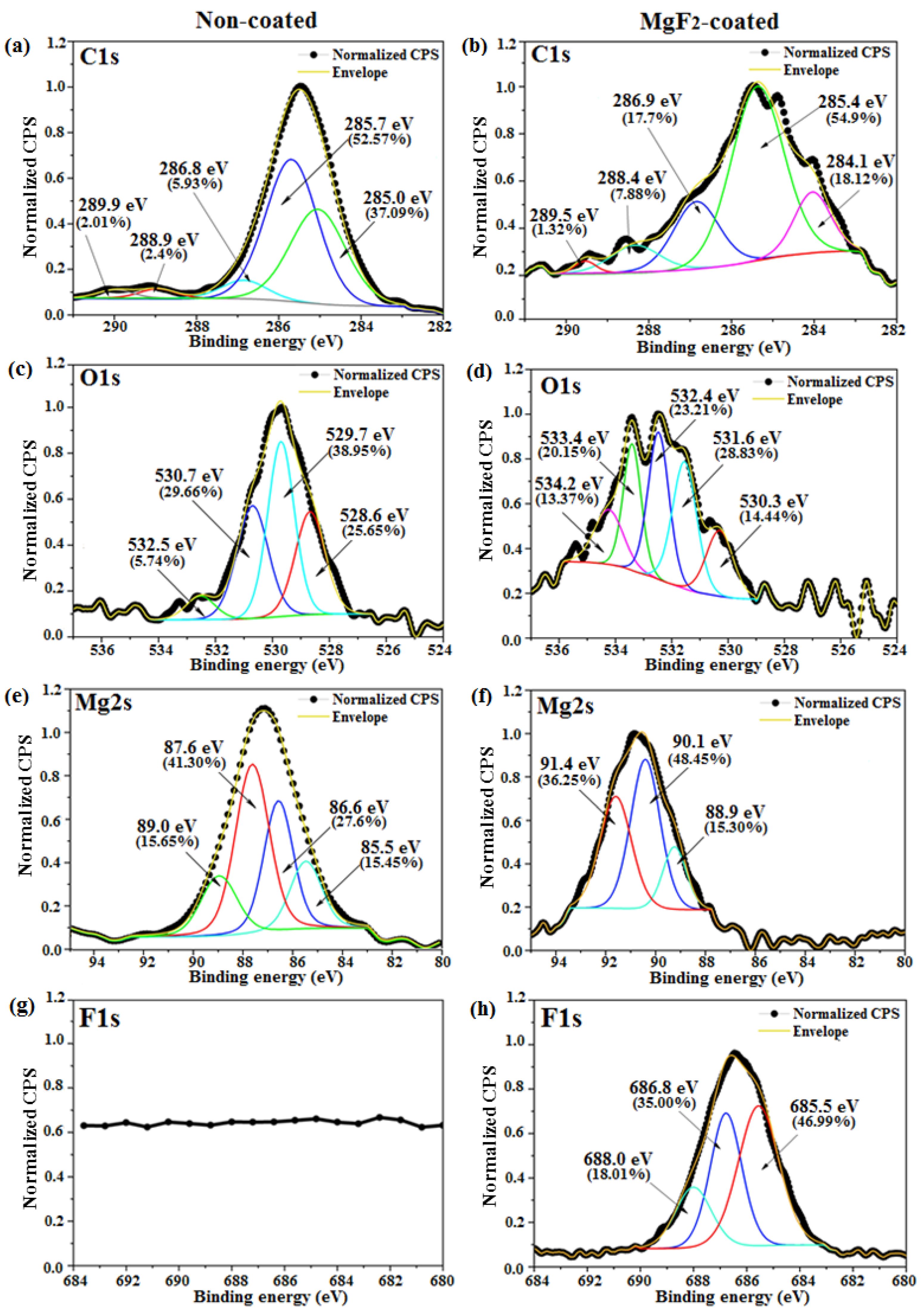
The presence of both metal-bound-F and metal-bound-O at the uppermost nm of the coated samples surfaces were detected.
(4)
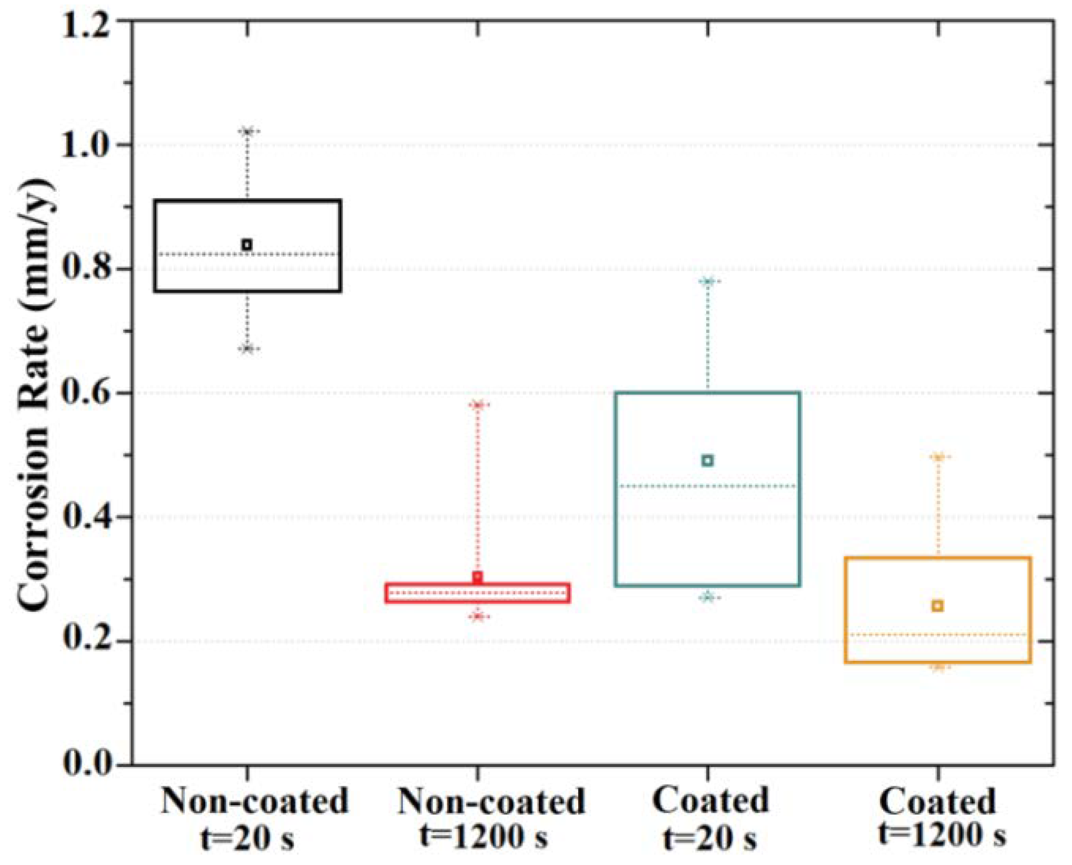
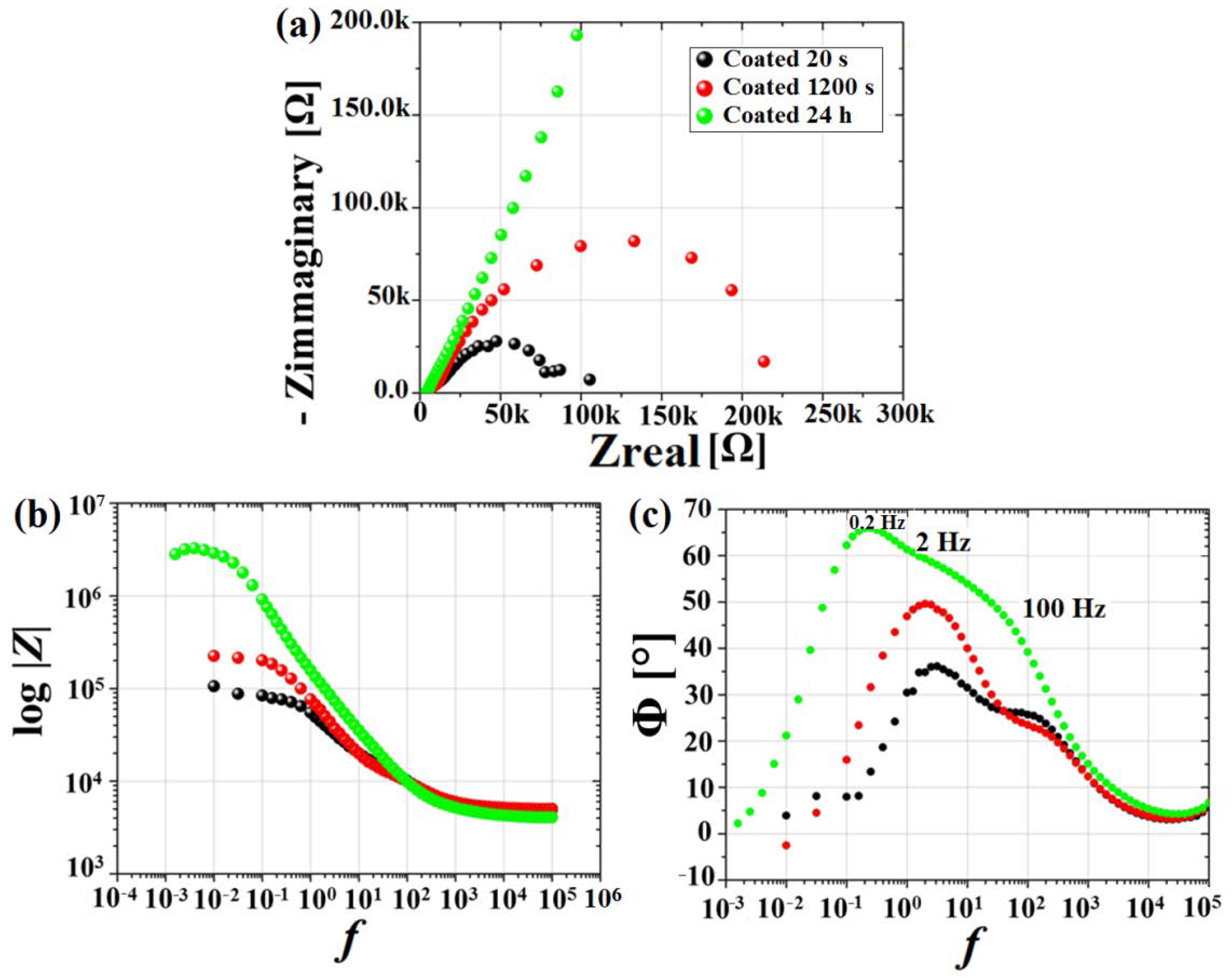
The MgF2 coating demonstrated an efficient role in retarding alloy degradation during the initial stages of exposure to the chloride-containing physiological solution up to 24 h, with the corrosion rate determined using EIS spectra decreasing from 0.49 mm/y to 0.01 mm/y.
These results demonstrated the effectiveness of the applied MgF2 film in slowing down alloy corrosion, allowing these materials to be competitive as dental and orthopedic products in the biodegradable implants market. A mechanical characterization, including nano-scratch-tests, is suggested to further investigate micro-hardness and coating adhesion and cohesion, respectively, in order to predict screw performances in an application scenario. For this purpose, a special set-up capable of characterizing these kinds of samples with complex shapes and small dimensions is required, and is currently under study.

Author Contributions

S.G.: Conceptualization, data curation, elaboration of figures and graphs, discussion of results and writing the original draft. M.L.N.: performed the EIS experiments, developed the electrochemical methodology and calculation of corrosion rates, writing and manuscript revision. M.S.: XPS analysis. S.R.: SEM-EDS, AFM analysis. V.S.: EIS data modelling using the RC equivalent circuits. C.P.: Conceptualization, supervision, writing and reviewing. D.M., M.B. and F.W.: Conceptualization, samples production, funding and draft validation. All authors have read and agreed to the published version of the manuscript.

Funding

The present research was supported by the Memorandum of Understanding between CNR-ICMATE (Genoa, IT) and Laval University-LBB (Quebec, CA), NSERC Collaborative Research Project and Ministry of Economy and Innovation, PRIMA Quebec (D.M.), and the Merit Scholarship Program for Foreign Students (PBEEE (No dossier FRQ: 0000274425), S.G.).

Institutional Review Board Statement

Not applicable.

Informed Consent Statement

Not applicable.

Data Availability Statement

The data presented in this study are available on request from the corresponding author(s). The data are not publicly available due to the fact that they are a subset of a bigger dataset covered by industrial secret (biotrics implants AG).

Acknowledgments

The authors would like to thank Pascale Chevallier, from the Quebec City Hospital Research Center for help and guidance in XPS analyses, ZeLMI, TU Berlin for the WDX analysis and Emanuela Bonino for the language revision. In addition, the authors would like to thank Jörg Nissen, Irene Preuss and Ing. Dirk Berger from ZeLMI TU, Berlin.

Conflicts of Interest

The authors declare no conflict of interest.

References

  1. Francolini, I.; Hall-Stoodley, L.; Stoodley, P. Biofilms, Biomaterials, and Device-Related Infections. In Biomaterials Science, 4th ed.; Academic Press: Cambridge, MA, USA, 2020; pp. 271–287. ISBN 978-0-12-816137-1. [Google Scholar] [CrossRef]
  2. Hu, R.-G.; Zhang, S.; Bu, J.-F.; Lin, C.-J.; Song, G.-L. Recent progress in corrosion protection of magnesium alloys by organic coatings. Prog. Org. Coat. 2012, 73, 129–141. [Google Scholar] [CrossRef]
  3. Chen, Y.; Xu, Z.; Smith, C.; Sankar, J. Recent advances on the development of magnesium alloys for biodegradable implants. Acta Biomater. 2014, 10, 4561–4573. [Google Scholar] [CrossRef]
  4. Witte, F. The history of biodegradable magnesium implants: A review. Acta Biomater. 2010, 6, 1680–1692. [Google Scholar] [CrossRef]
  5. Hartwig, A. Role of magnesium in genomic stability. Mutat. Res. Fundam. Mol. Mech. Mutagen. 2001, 475, 113–121. [Google Scholar] [CrossRef]
  6. Trumbo, P.; Schlicker, S.; Yates, A.; Poos, M. Dietary Reference Intakes for Energy, Carbohydrate, Fiber, Fat, Fatty Acids, Cholesterol, Protein and Amino Acids. J. Am. Diet. Assoc. 2002, 102, 1621–1630. [Google Scholar] [CrossRef]
  7. Staiger, M.P.; Pietak, A.M.; Huadmai, J.; Dias, G. Magnesium and its alloys as orthopedic biomaterials: A review. Biomaterials 2006, 27, 1728–1734. [Google Scholar] [CrossRef]
  8. Xu, Y.-L.; Wang, L.; Huang, M.; Gensch, F.; Kainer, K.U.; Hort, N. The Effect of Solid Solute and Precipitate Phase on Young’s Modulus of Binary Mg-RE Alloys. Adv. Eng. Mater. 2018, 20, 1800271. [Google Scholar] [CrossRef]
  9. Zhang, Y.; Xu, J.; Ruan, Y.C.; Yu, M.K.; O’Laughlin, M.; Wise, H.; Chen, D.; Tian, L.; Shi, D.; Wang, J.; et al. Implant-derived magnesium induces local neuronal production of CGRP to improve bone-fracture healing in rats. Nat. Med. 2016, 22, 1160–1169. [Google Scholar] [CrossRef] [PubMed] [Green Version]
  10. Hung, C.-C.; Chaya, A.; Liu, K.; Verdelis, K.; Sfeir, C. The role of magnesium ions in bone regeneration involves the canonical Wnt signaling pathway. Acta Biomater. 2019, 98, 246–255. [Google Scholar] [CrossRef]
  11. Yu, Y.; Lu, H.; Sun, J. Long-term in vivo evolution of high-purity Mg screw degradation—Local and systemic effects of Mg degradation products. Acta Biomater. 2018, 71, 215–224. [Google Scholar] [CrossRef] [PubMed]
  12. Kannan, M.B.; Raman, R.S. In vitro degradation and mechanical integrity of calcium-containing magnesium alloys in modified-simulated body fluid. Biomaterials 2008, 29, 2306–2314. [Google Scholar] [CrossRef]
  13. Jafari, S.; Raman, R.S.; Davies, C.H. Corrosion fatigue of a magnesium alloy in modified simulated body fluid. Eng. Fract. Mech. 2015, 137, 2–11. [Google Scholar] [CrossRef]
  14. Gu, X.; Zhou, W.; Zheng, Y.; Cheng, Y.; Wei, S.; Zhong, S.; Xi, T.; Chen, L. Corrosion fatigue behaviors of two biomedical Mg alloys—AZ91D and WE43—In simulated body fluid. Acta Biomater. 2010, 6, 4605–4613. [Google Scholar] [CrossRef] [PubMed]
  15. Choudhary, L.; Raman, R.S. Magnesium alloys as body implants: Fracture mechanism under dynamic and static loadings in a physiological environment. Acta Biomater. 2012, 8, 916–923. [Google Scholar] [CrossRef]
  16. Pichler, K.; Fischerauer, S.; Ferlic, P.; Martinelli, E.; Brezinsek, H.-P.; Uggowitzer, P.J.; Löffler, J.F.; Weinberg, A.-M. Immunological Response to Biodegradable Magnesium Implants. JOM 2014, 66, 573–579. [Google Scholar] [CrossRef]
  17. Song, G. Control of biodegradation of biocompatable magnesium alloys. Corros. Sci. 2007, 49, 1696–1701. [Google Scholar] [CrossRef]
  18. Bamberger, M.; Dehm, G. Trends in the Development of New Mg Alloys. Annu. Rev. Mater. Sci. 2008, 38, 505–533. [Google Scholar] [CrossRef]
  19. Deng, M.; Wang, L.; Höche, D.; Lamaka, S.V.; Wang, C.; Snihirova, D.; Jin, Y.; Zhang, Y.; Zheludkevich, M.L. Approaching “stainless magnesium” by Ca micro-alloying. Mater. Horiz. 2020, 8, 589–596. [Google Scholar] [CrossRef]
  20. Jana, A.; Das, M.; Balla, V.K. In vitro and in vivo degradation assessment and preventive measures of biodegradable Mg alloys for biomedical applications. J. Biomed. Mater. Res. Part A 2021, 110, 462–487. [Google Scholar] [CrossRef] [PubMed]
  21. Liu, L.; Peng, F.; Zhang, D.; Li, M.; Huang, J.; Liu, X. A tightly bonded reduced graphene oxide coating on magnesium alloy with photothermal effect for tumor therapy. J. Magnes. Alloys 2021. [Google Scholar] [CrossRef]
  22. Geng, F.; Tan, L.L.; Jin, X.X.; Yang, J.Y.; Yang, K. The preparation, cytocompatibility, and in vitro biodegradation study of pure β-TCP on magnesium. J. Mater. Sci. Mater. Med. 2009, 20, 1149–1157. [Google Scholar] [CrossRef]
  23. Xin, Y.; Jiang, J.; Huo, K.; Tang, G.; Tian, X.; Chu, P.K. Corrosion resistance and cytocompatibility of biodegradable surgical magnesium alloy coated with hydrogenated amorphous silicon. J. Biomed. Mater. Res. Part A 2008, 89A, 717–726. [Google Scholar] [CrossRef]
  24. Chowdhury, M.A.; Hossain, N.; Shahid, A.; Alam, J.; Hossain, S.M.; Uddin, I.; Rana, M. Development of SiC–TiO2-Graphene neem extracted antimicrobial nano membrane for enhancement of multiphysical properties and future prospect in dental implant applications. Heliyon 2022, 8, e10603. [Google Scholar] [CrossRef] [PubMed]
  25. Chowdhury, M.A.; Hossain, H.; Hossain, N.; Hossen, Z.; Kowser, A.; Rana, M. Advances in Coatings on Mg Alloys and Their Anti-Microbial Activity for Implant Applications. Arab. J. Chem. 2022, 15, 104214. [Google Scholar] [CrossRef]
  26. Rahman, M.; Chowdhury, M.A.; Mia, S.; Ali, R.; Rahman, A.; Ali, O.; Mahmud, S. Fabrication and characterization of hybrid coating on Mg–Zn–Ca Mg alloy for enhanced corrosion and degradation resistance as medical implant. Ceram. Int. 2022, 48, 23314–23324. [Google Scholar] [CrossRef]
  27. Song, Y.; Shan, D.; Han, E. Electrodeposition of hydroxyapatite coating on AZ91D magnesium alloy for biomaterial application. Mater. Lett. 2008, 62, 3276–3279. [Google Scholar] [CrossRef]
  28. Xu, L.; Pan, F.; Yu, G.; Yang, L.; Zhang, E.; Yang, K. In vitro and in vivo evaluation of the surface bioactivity of a calcium phosphate coated magnesium alloy. Biomaterials 2009, 30, 1512–1523. [Google Scholar] [CrossRef]
  29. Chiu, K.Y.; Wong, M.; Cheng, F.; Man, H. Characterization and corrosion studies of fluoride conversion coating on degradable Mg implants. Surf. Coat. Technol. 2007, 202, 590–598. [Google Scholar] [CrossRef]
  30. Zhang, C.; Zhang, J.; Zhang, S.; Wang, Z. Comparison of calcium phosphate coatings on AZ31 and fluoride-treated AZ31 alloy prepared by hydrothermal method and their electrochemical corrosion behaviour. Mater. Chem. Phys. 2018, 220, 395–401. [Google Scholar] [CrossRef]
  31. Whitford, G. Intake and Metabolism of Fluoride. Adv. Dent. Res. 1994, 8, 5–14. [Google Scholar] [CrossRef]
  32. Drynda, A.; Hassel, T.; Hoehn, R.; Perz, A.; Peuster, M.; Bach, F.-W. Development and biocompatibility of a novel corrodible fluoride-coated magnesium-calcium alloy with improved degradation kinetics and adequate mechanical properties for cardiovascular applications. J. Biomed. Mater. Res. Part A 2009, 93A, 763–775. [Google Scholar] [CrossRef] [PubMed]
  33. Lozano, R.M.; Pérez-Maceda, B.T.; Carboneras, M.; Onofre-Bustamante, E.; García-Alonso, M.C.; Escudero, M.L. Response of MC3T3-E1 osteoblasts, L929 fibroblasts, and J774 macrophages to fluoride surface-modified AZ31 magnesium alloy. J. Biomed. Mater. Res. Part A 2013, 101, 2753–2762. [Google Scholar] [CrossRef] [PubMed]
  34. Yan, T.; Tan, L.; Xiong, D.; Liu, X.; Zhang, B.; Yang, K. Fluoride treatment and in vitro corrosion behavior of an AZ31B magnesium alloy. Mater. Sci. Eng. C 2010, 30, 740–748. [Google Scholar] [CrossRef]
  35. Casanova, P.Y.; Jaimes, K.J.; Parada, N.J.; A Hernández-Barrios, C.; Aparicio, M.; Viejo, F.; Coy, A.E. Synthesis and evaluation of MgF2 coatings by chemical conversion on magnesium alloys for producing biodegradable orthopedic implants of temporary use. J. Phys. Conf. Ser. 2013, 466, 012003. [Google Scholar] [CrossRef] [Green Version]
  36. Bakhsheshi-Rad, H.R.; Idris, M.H.; Kadir, M.R.A.; Daroonparvar, M. Effect of fluoride treatment on corrosion behavior of Mg–Ca binary alloy for implant application. Trans. Nonferrous Met. Soc. China 2013, 23, 699–710. [Google Scholar] [CrossRef]
  37. Witte, F.; Fischer, J.; Nellesen, J.; Vogt, C.; Vogt, J.; Donath, T.; Beckmann, F. In vivo corrosion and corrosion protection of magnesium alloy LAE442. Acta Biomater. 2010, 6, 1792–1799. [Google Scholar] [CrossRef]
  38. Jiang, H.; Wang, J.; Chen, M.; Liu, D. Biological activity evaluation of magnesium fluoride coated Mg-Zn-Zr alloy in vivo. Mater. Sci. Eng. C 2017, 75, 1068–1074. [Google Scholar] [CrossRef]
  39. Wang, P.; Liu, J.; Shen, S.; Li, Q.; Luo, X.; Xiong, P.; Gao, S.; Yan, J.; Cheng, Y.; Xi, T. In Vitro and In Vivo Studies on Two-Step Alkali-Fluoride-Treated Mg–Zn–Y–Nd Alloy for Vascular Stent Application: Enhancement in Corrosion Resistance and Biocompatibility. ACS Biomater. Sci. Eng. 2019, 5, 3279–3292. [Google Scholar] [CrossRef] [PubMed]
  40. Gao, X.; Dai, C.Y.; Jia, Q.; Zhai, C.; Shi, H.; Yang, Y.; Zhao, B.C.; Cai, H.; Lee, E.-S.; Jiang, H.B. In Vivo Corrosion Behavior of Biodegradable Magnesium Alloy by MAF Treatment. Scanning 2021, 2021, 5530788. [Google Scholar] [CrossRef] [PubMed]
  41. Lou, J.; Sun, Y.; Chen, Y.; Zan, R.; Peng, H.; Yang, S.; Kang, X.; Peng, Z.; Wang, W.; Zhang, X. Effects of MgF2 coating on the biodegradation and biological properties of magnesium. Surf. Coat. Technol. 2021, 422, 127552. [Google Scholar] [CrossRef]
  42. Cheng, S.; Wang, W.; Wang, D.; Li, B.; Zhou, J.; Zhang, D.; Liu, L.; Peng, F.; Liu, X.; Zhang, Y. An in vitro and in vivo comparison of Mg(OH)2-, MgF2- and HA-coated Mg in degradation and osteointegration. Biomater. Sci. 2020, 8, 3320–3333. [Google Scholar] [CrossRef]
  43. Amberg, R.; Elad, A.; Rothamel, D.; Fienitz, T.; Szakacs, G.; Heilmann, S.; Witte, F. Design of a migration assay for human gingival fibroblasts on biodegradable magnesium surfaces. Acta Biomater. 2018, 79, 158–167. [Google Scholar] [CrossRef]
  44. Kačarević, P.; Rider, P.; Elad, A.; Tadic, D.; Rothamel, D.; Sauer, G.; Bornert, F.; Windisch, P.; Hangyási, D.B.; Molnar, B.; et al. Biodegradable magnesium fixation screw for barrier membranes used in guided bone regeneration. Bioact. Mater. 2021, 14, 15–30. [Google Scholar] [CrossRef]
  45. Liu, J.; Kerns, D.G. Mechanisms of Guided Bone Regeneration: A Review. Open Dent. J. 2014, 8, 56–65. [Google Scholar] [CrossRef] [PubMed] [Green Version]
  46. Tadic, D.; Bielenstein, O. Implant for Covering Maxillary Bone Defects in the Jaw Region and Method for Producing the Same. U.S. Patent US20180036127, 8 February 2018. [Google Scholar]
  47. Müller, W.D.; Nascimento, M.L.; Zeddies, M.; Córsico, M.; Gassa, L.M.; Mele, M.A.F.L.D. Corrosion Studies Using Potentiodynamic and EIS Electrochemical Techniques. Mater. Res. 2007, 10, 5–10. [Google Scholar] [CrossRef] [Green Version]
  48. Bard, A.J.; Faulkner, L.R. Electrochemical Methods: Fundamentals and Applications, 2nd ed.; Stern, M., Geary, A.L., Eds.; Wiley: New York, NY, USA, 2001; Volume 104, pp. 56–63. [Google Scholar]
  49. King, A.; Birbilis, N.; Scully, J. Accurate Electrochemical Measurement of Magnesium Corrosion Rates; a Combined Impedance, Mass-Loss and Hydrogen Collection Study. Electrochim. Acta 2014, 121, 394–406. [Google Scholar] [CrossRef]
  50. Orazem, M.E.; Tribollet, B. Electrochemical Impedance Spectroscopy; John Wiley & Sons, Inc.: Hoboken, NJ, USA, 2008. [Google Scholar]
  51. Mohan, R.; Harshavardhana, N.; Chaudhari, M.; Jeyanthi, S.; Abimannan, G. Analysis on surface finish and chip morphology during dry turning process. Mater. Today Proc. 2021, 46, 999–1002. [Google Scholar] [CrossRef]
  52. Han, Y.; Liu, M.; Li, K.; Zuo, Y.; Wei, Y.; Xu, S.; Zhang, G.; Song, C.; Zhang, Z.; Guo, X. Facile synthesis of morphology and size-controlled zirconium metal–organic framework UiO-66: The role of hydrofluoric acid in crystallization. CrystEngComm 2015, 17, 6434–6440. [Google Scholar] [CrossRef]
  53. Aljarrah, M.; Alnahas, J.; Alhartomi, M. Thermodynamic Modeling and Mechanical Properties of Mg-Zn-{Y, Ce} Alloys: Review. Crystals 2021, 11, 1592. [Google Scholar] [CrossRef]
  54. Makkar, P.; Kang, H.J.; Padalhin, A.R.; Park, I.; Moon, B.-G.; Lee, B.T. Development and properties of duplex MgF2/PCL coatings on biodegradable magnesium alloy for biomedical applications. PLoS ONE 2018, 13, e0193927. [Google Scholar] [CrossRef] [Green Version]
  55. Wan, H.; Hu, X. One-step solve-thermal process for the construction of anticorrosion bionic superhydrophobic surfaces on magnesium alloy. Mater. Lett. 2016, 174, 209–212. [Google Scholar] [CrossRef]
  56. Yang, C.-W.; Liu, C.; Lin, D.-J.; Yeh, M.-L.; Lee, T.-M. Hydrothermal treatment and butylphosphonic acid derived self-assembled monolayers for improving the surface chemistry and corrosion resistance of AZ61 magnesium alloy. Sci. Rep. 2017, 7, 16910. [Google Scholar] [CrossRef] [PubMed]
  57. Zhang, X.; Wu, G.; Peng, X.; Li, L.; Feng, H.; Gao, B.; Huo, K.; Chu, P.K. Mitigation of Corrosion on Magnesium Alloy by Predesigned Surface Corrosion. Sci. Rep. 2015, 5, 17399. [Google Scholar] [CrossRef] [PubMed] [Green Version]
  58. Palchan, I.; Crespin, M.; Estrade-Szwarckopf, H.; Rousseau, B. Graphite fluorides: An XPS study of a new type of C-F bonding. Chem. Phys. Lett. 1989, 157, 321–327. [Google Scholar] [CrossRef]
  59. He, Z.X.; Pong, W. X-ray photoelectron spectra of MgH2. Phys. Scr. 1990, 41, 930. [Google Scholar] [CrossRef]
  60. Le Febvrier, A.; Jensen, J.; Eklund, P. Wet-cleaning of MgO(001): Modification of surface chemistry and effects on thin film growth investigated by x-ray photoelectron spectroscopy and time-of-flight secondary ion mass spectroscopy. J. Vac. Sci. Technol. A Vac. Surf. Films 2017, 35, 021407. [Google Scholar] [CrossRef] [Green Version]
  61. Murch, G.; Thorn, R. Relation between orbital binding energies and ionicities in alkali and alkaline earth flourides. J. Phys. Chem. Solids 1980, 41, 785–791. [Google Scholar] [CrossRef]
  62. Kouisni, L.; Azzi, M.; Dalard, F.; Maximovitch, S. Phosphate coatings on magnesium alloy AM60: Part 2: Electrochemical behaviour in borate buffer solution. Surf. Coat. Technol. 2005, 192, 239–246. [Google Scholar] [CrossRef]
  63. Guadarrama-Muñoz, F.; Mendoza-Flores, J.; Duran-Romero, R.; Genesca, J. Electrochemical study on magnesium anodes in NaCl and CaSO4–Mg(OH)2 aqueous solutions. Electrochim. Acta 2006, 51, 1820–1830. [Google Scholar] [CrossRef]
  64. Witte, F.; Hort, N.; Vogt, C.; Cohen, S.; Kainer, K.U.; Willumeit, R.; Feyerabend, F. Degradable biomaterials based on magnesium corrosion. Curr. Opin. Solid State Mater. Sci. 2008, 12, 63–72. [Google Scholar] [CrossRef] [Green Version]
  65. Jamesh, M.; Kumar, S.; Narayanan, T.S. Corrosion behavior of commercially pure Mg and ZM21 Mg alloy in Ringer’s solution—Long term evaluation by EIS. Corros. Sci. 2011, 53, 645–654. [Google Scholar] [CrossRef]
  66. Sun, Y.; Wang, R.; Peng, C.; Cai, Z. Microstructure and corrosion behavior of as-extruded Mg-xLi-3Al-2Zn-0.2Zr alloys (x = 5, 8, 11 wt.%). Corros. Sci. 2020, 167, 108487. [Google Scholar] [CrossRef]
  67. Hou, R.; Victoria-Hernandez, J.; Jiang, P.; Willumeit-Romer, R.; Feyerabend, B.L.; Yi, S.; Letzig, D.; Feyerabend, F. In vitro evaluation of the ZX11 magnesium alloy as potential bone plate. Acta Biomater. 2019, 97, 608–622. [Google Scholar] [CrossRef] [PubMed]
  68. Wang, L.; Snihirova, D.; Deng, M.; Wang, C.; Vaghefinazari, B.; Wiese, G.; Langridge, M.; Höche, D.; Lamaka, S.V.; Zheludkevich, M.L. Insight into physical interpretation of high frequency time constant in electrochemical impedance spectra of Mg. Corros. Sci. 2021, 187, 109501. [Google Scholar] [CrossRef]
  69. Zaffora, A.; Franco, F.D.; Virtù, D.; Pavia, F.C.; Ghersi, G.; Virtanen, S.; Santamaria, M. Tuning of the Mg alloy AZ31 anodizing process for biodegradable implants. ACS Appl. Mater. Interfaces 2021, 13, 12866–12876. [Google Scholar] [CrossRef]
Figure 1. Schematic representation of the mini-cell system adopted in this work.
Materials 15 08245 g001
Figure 2. SEM analysis of non-coated (a) and MgF2-coated screws (e); high magnification micrographs of the tip (b,f), thread (c,g), and head (d,h).
Materials 15 08245 g002
Figure 3. EDS mapping of MgF2-coated screws; elements distribution of the tip (af) and of the thread (gl).
Materials 15 08245 g003
Figure 4. EDS analyses of areas in Figure 2 for non-coated (a) and MgF2-coated samples (b).
Materials 15 08245 g004
Figure 5. SEM analysis of a cross-sectioned MgF2-coated sample (a); WDX spectrum (b) and elemental compositions (c) of the coating (black square of (a)); maps of elemental distribution (di). This analysis was performed at ZeLMI, TU Berlin.
Materials 15 08245 g005
Figure 6. AFM analysis performed on screws head: 2D images of non-coated (a) and coated (b) screws; 3D-images of non-coated (c) and coated (d) screws; roughness measurements (e).
Materials 15 08245 g006
Figure 7. Survey spectra (a) and concentration of elements (at%), as well as F/Mg ratio (b), of non-coated (blue) and coated surfaces (red).
Materials 15 08245 g007
Figure 8. High-resolution spectra of C1s (a,b), O1s (c,d), Mg2s (e,f), and F1s (g,h) of non-coated and coated samples, respectively.
Materials 15 08245 g008
Figure 9. EIS spectra obtained for non-coated (left) and coated (right) samples at the start (20 s) and after 1200 s exposure to the electrolyte. Nyquist plot (a,b); Bode modulus (c,d); Bode phase (e,f).
Materials 15 08245 g009
Figure 10. Box plot of the corrosion rate results obtained for non-coated and MgF2-coated samples.
Materials 15 08245 g010
Figure 11. Electrical equivalent circuits used in this study. Representation of equivalent circuit for non-coated (a) and coated (b) samples, respectively, and the fitted electrical parameters (c).
Materials 15 08245 g011
Figure 12. EIS spectra obtained for coated samples at the start (20 s) and after 1200 s and 24 h of exposure to the electrolyte. Nyquist plot (a); Bode modulus (b); Bode phase (c).
Materials 15 08245 g012
Table 1. Recent studies on MgF2 coating on Mg-based materials.
Mg-AlloySample ShapeTreatmentOutcomesApplicationsRef.
Mg-3Zn-0.5ZrCylinders
(Ø = 3 mm; h = 10 mm)
HF (20%); 6 h; 37 °CDecreased corrosion rate; promotion of new bone formationOrthopedic applications2017 [38]
Mg-2Zn-0.5Y-0.5NdDiscs
(Ø = 10 mm; h = 2 mm)
HF (40%); 24 h; room temperatureNo subcutaneous gas cavities or significant inflammatory cell infiltrationCardiovascular stents2019 [39]
AZ31Plates
(5 mm × 7 mm × 2 mm)
Microfluoruration in saturated NH4HF2 solution at 190 VImproved corrosion resistance; reduced H2(g) bubbles generationMedical implant materials2021 [40]
Mg (99.98%)Sheets
(12 mm × 10 mm × 1 mm)
HF (40%);
24, 48, 96 h; room temperature
Decreased corrosion rate; great cytocompatibility; good attachment and growth of osteoblasts on the surfaceOrthopedic applications2021 [41]
Mg (>99.99 wt.%)Plates
(10 mm × 1 mm × 2 mm)
Rodes (Ø = 10 mm; h = 2 mm)
HF (40%); 72 h; room temperatureBeneficial for the osteogenic differentiation of MC3T3-E1 cells and the vascularization of human umbilical vein endothelial cells (HUVECs)Orthopedic applications2020 [42]
Mg-2Y-1Mn-1ZnScrewsHF (40%);
room temperature
Decreased corrosion rate; reduced H2(g) bubbles generationOrthopedic applications; Bone regenerationThis work
Table 2. Nominal composition of WZM211 alloy (wt.%).
YZnMnMg
WZM2112.01.01.0bal.
Table 3. Average polarization resistance and corrosion rates obtained for the machined and coated samples tested.
Non-CoatedCoatedNon-CoatedCoated
Rp [Ω.cm2]CR [mm/y]
20 s359 ± 14694 ± 850.84 ± 0.030.49 ± 0.06
1200 s1036 ± 1981323 ± 1440.30 ± 0.030.26 ± 0.03
Publisher’s Note: MDPI stays neutral with regard to jurisdictional claims in published maps and institutional affiliations.

