Abstract
The transport mechanism of HfO2-based metal-ferroelectric-metal (MFM) capacitors was investigated using low-frequency noise (LFN) measurements for the first time. The current–voltage measurement results revealed that the leakage behavior of the fabricated MFM capacitor was caused by the trap-related Poole–Frenkel transport mechanism, which was confirmed by the LFN measurements. The current noise power spectral densities (SI) obtained from the LFN measurements followed 1/f noise shapes and exhibited a constant electric field (E) × SI/I2 noise behavior. No polarization dependency was observed in the transport characteristics of the MFM capacitor owing to its structural symmetry.
1. Introduction
Hafnium oxide (HfO2)-based ferroelectric (FE) materials can be used in memory devices and negative capacitance field-effect transistors (FETs) [1,2,3,4]. Owing to their outstanding material properties, such as a large dielectric constant of 20–25 and a high-energy bandgap of ~5.7 eV, HfO2-based metal-ferroelectric-metal (MFM) capacitors have high capacitance, low leakage current, and strong ferroelectric properties. HfO2 ferroelectric films can be deposited using an atomic layer deposition (ALD) system in a complementary metal-oxide-semiconductor (CMOS)-compatible process with excellent thickness controllability and large-area uniformity.
Current–voltage (I–V) and capacitance–voltage (C–V) measurements are commonly used to evaluate MFM capacitors. The ferroelectric properties of HfO2-based MFM capacitors based on I–V and C–V measurements have also been reported as functions of frequency and temperature [5]. Giusi et al. [6] reported Ru-based capacitors characterized by low-frequency noise (LFN) measurements. LFN measurements can be used to analyze the conduction mechanism and evaluate the device/material reliability [7,8,9]. Recently, Shin et al. reported a study on a metal-FE-insulator-semiconductor (MFIS) FET based on noise measurements [7,8,9]. They investigated conduction mechanisms and noise fluctuation depending on the FE polarization direction and the process conditions. The MFIS configuration is asymmetric, with an additional interface between the FE and the semiconductor, whereas the MFM device has a symmetric interface between the FE and the metal electrodes. FE polarization has been reported to play a significant role in MFIS FET noise behavior; hence, analyzing FE material is important. However, LFN characteristics have not been reported for HfO2-based MFM capacitors. This study comprehensively analyzed a HfO2-based MFM capacitor using LFN measurements.
2. Device Fabrication
The MFM capacitor consisted of 100-nm-thick TiN metal, 10-nm-thick HfO2 ferroelectric oxide, and 100-nm-thick TiN metal layers grown on a quartz substrate (Figure 1a). The fabrication process was as follows: After cleaning the wafer in wet chemical solutions (acetone, methanol, and deionized water), a 100-nm-thick TiN film was deposited at room temperature using a radio frequency (RF) sputtering machine. The bottom electrode pattern was defined using a fluorine-based plasma-etching process. A 10-nm-thick un-doped HfO2 ferroelectric layer was deposited via an atomic layer deposition (ALD) method at 220 °C using a TEMA-Hf precursor and 100 g/m3 of O3. Then, a 100-nm-thick TiN film was deposited as the top electrode, which was patterned with a diameter of 100 μm. The top TiN film and the un-doped HfO2 were subsequently etched to form capacitors using SF6/Ar and CF4/O2 gas mixtures. The fabricated MFM capacitors were annealed using rapid thermal annealing (RTA) at 650 °C for 1 min to obtain the desired ferroelectric properties. Cross-sectional transmission electron microscopy (TEM) images and energy-disperse spectroscopy (EDS) analysis of the fabricated MFM capacitor (shown in Figure 2) confirm the un-doped HfO2 of a thickness of 10 nm. Detailed ferroelectric characteristics, including X-ray diffraction analysis, can be found in ref. [5].
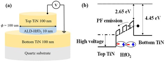
Figure 1.
(a) Schematic of the fabricated HfO2-based MFM capacitor. (b) Illustration of the transport mechanism in the MFM device with an applied voltage.
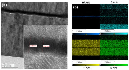
Figure 2.
(a) Cross-sectional TEM images. (b) EDS analysis of the fabricated HfO2-based MFM capacitor.
3. Characterization and Discussions
The I–V and LFN characteristics were measured in a shielding box at atmospheric pressure using a NOISYS7 machine (Synergie-concept) [10]. We measured fifteen devices from three samples (five from each sample), and no significant variation was observed.
Figure 3a shows the leakage current density (J) as a function of the bias voltage of the fabricated MFM capacitor. The leakage current behavior in both the forward and reverse-bias regimes exhibits similar rectifying characteristics attributed to the Schottky barrier between the HfO2 and the TiN electrode. The asymmetric characteristics in the forward and reverse directions are attributed to the asymmetric structures of the top and bottom electrodes. No hysteresis in the current–voltage characteristics was observed as a function of the bias sweep direction, whereas the capacitance–voltage characteristics exhibited typical butterfly hysteresis characteristics, as reported in [5]. No difference was observed in the current–voltage characteristics as a function of the polarization direction, which implies the same noise behavior. To determine the transport mechanism, ln (I/V) versus V0.5 and ln (I/V2) versus 1/V are plotted in Figure 4a and 4b, respectively [9]. ln (I/V) versus V0.5 follows a straight line from 0.7 to 3.2 V in Figure 4a, which implies that the leakage current phenomenon is associated with the Poole–Frenkel (PF) mechanism caused by the oxide traps and vacancies in the HfO2 FE layer (see Figure 1b) [7,8,9]. In contrast, the Fowler–Nordheim (FN) mechanism caused by tunneling through the HfO2 layer becomes dominant at voltages higher than 2.5 V, as shown in Figure 4b [11].
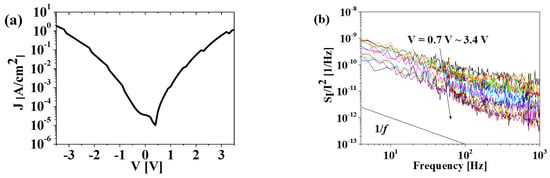
Figure 3.
(a) Logarithmic scale of current density as a function of voltage in the MFM capacitor. (b) Normalized current power spectral density (SI/I2) versus frequency as a function of bias voltage ranging from 0.7 to 3.4 V.
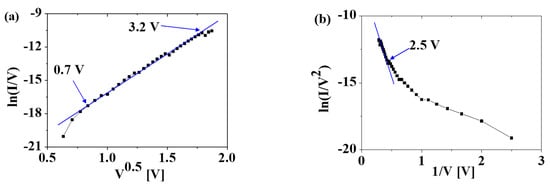
Figure 4.
(a) ln (I/V) versus V0.5 and (b) ln (I/V2) versus 1/V show the Poole–Frenkel emission and the Fowler–Nordheim emission, respectively. From the straight lines, the dominant leakage mechanisms are the Poole–Frenkel mechanism from 0.7 to 3.2 V and the Fowler–Nordheim mechanism at V > 2.5 V.
Figure 3b shows the bias-dependent LFN characteristics of the MFM device measured in the frequency (f) range of 4–103 Hz. The bias voltage was applied from 0.5 to 3 V to the top TiN electrode and for the bottom TiN electrode. The normalized current noise power spectral density (SI/I2) curve exhibited a 1/f noise shape, as shown in Figure 3b, regardless of the bias voltage, which is consistent with the noise results of the reported MIM capacitors and MFIS FET with positive polarization [6,7,8,9]. The noise levels (SI/I2) decreased while the bias voltage and measurement frequency increased. The SI/I2 values were inversely proportional to the current density, as shown in Figure 5a. Figure 5b shows E × SI/I2 versus the current density, from which no dependence on the current density is observed. Therefore, we suggest that the origin of the noise is primarily related to the PF emission mechanism, following the model given in [9,12]:
where β is the field enhancement factor. The β value increases as thermal field emission is added to the PF emission [9,12]. The β value of the HfO2 MFM capacitor fabricated in this study was approximately three orders of magnitude lower than the one reported in [9]. In addition, no increase in the β value as a function of the current density was observed, indicating that the thermal emission was negligible and that only a PF mechanism was responsible for the leakage behavior.
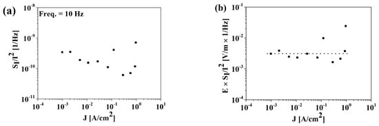
Figure 5.
(a) SI/I2 versus J and (b) E × SI/I2 versus J at f = 10 Hz.
The SI versus the current density is plotted in Figure 6a to investigate the FE material quality. The SI is proportional to J2 in the current density range below J = 100 A/cm2, which can be expressed by [6,13,14]:
where B is the trap-related value, which depends on film quality. The estimated B values of the fabricated devices range from 8 × 10¹⁷ to 3 × 10¹⁸. These values are comparable to those reported for SrTiO3 MIM capacitors [6].
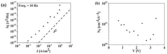
Figure 6.
(a) Current power spectral density (SI) as a function of current density (J) at f = 10 Hz for the fabricated MFM capacitor. The dashed line indicates J2. (b) Oxide trap density (Nt) versus voltage extracted from SI measurements.
The oxide trap density (Nt) can be extracted from the measured SI using the following equations [15,16]:
where A is the capacitor area (=7.85 × 10⁻⁵ cm2), α is the oxide tunneling attenuation given by , is the blocking area (= πr2, where r is half of the oxide thickness [15,16]), kT is the thermal energy, h is Planck’s constant, q is the electron charge, m* is the effective mass, and ΦB is the barrier height. With m* = 0.15 × m0 (m0 is the electron mass) [17] and ΦB = 1.8 eV [9], and α is calculated as 6.3 × 107 cm−1. Consequently, Nt versus the voltage is plotted in Figure 6b. The derived Nt was as low as 1.6 × 1020 cm−3·eV−1, comparable to that reported in a previous study [15]. For comparison, the Nt characteristics were also derived from the difference in the slope of the capacitance–frequency (C–F) curves, that is, the (CF slope) method [18]. Figure 7a,b shows the (CF) characteristics and the extracted Nt versus voltage. Notably, the (CF slope) method results in relatively lower Nt values compared to other methods [18]. Therefore, the difference observed between the two methods in this study is not atypical.
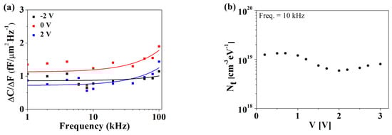
Figure 7.
(a) (C F) versus measurement frequency and (b) oxide trap density (Nt) calculated using the (C F slope) method and measured at 10 kHz.
4. Conclusions
An HfO2-based MFM capacitor was fabricated and characterized using I–V and noise measurements. The device exhibited a constant of E × SI/I2 noise values and noise shapes of 1/f, indicating that the dominant transport mechanism is a trap-related PF emission caused by trapping in the oxide defects. The oxide trap density, Nt, extracted from the noise measurements was as low as 1.6 × 1020 cm−3·eV−1. The important finding is that the transport mechanism of the MFM capacitor itself has no dependency on the polarization direction, whereas the asymmetric MFIS configuration has different mechanisms depending on the bias voltage polarity. The MFM capacitor exhibited similar behavior to that of the positive polarization case of the MFIS device.
Author Contributions
Investigation, conceptualization, methodology, writing—original draft, K.-S.I.; investigation, methodology, writing—review, and editing, S.S.; investigation, methodology, C.-H.J.; conceptualization, supervision, writing—review and editing, H.-Y.C. All authors have read and agreed to the published version of the manuscript.
Funding
This work was supported by the Basic Science Research Program (2015R1A6A1A03031833), the National R&D Program through the National Research Foundation of Korea (NRF) funded by Ministry of Science and ICT (2019M3F5A1A01077147, 2022M3I8A1077243), and Research Foundation of Korea (NRF) funded by the Ministry of Education, Science and Technology (MEST) (NRF-2022R1A2C1003596).
Institutional Review Board Statement
Not applicable.
Informed Consent Statement
Not applicable.
Data Availability Statement
Data supporting the findings of this study are available from the corresponding author upon reasonable request.
Conflicts of Interest
The authors declare no conflict of interest.
References
- Li, S.; Zhou, D.; Shi, Z.; Hoffmann, M.; Mikolajick, T.; Schroeder, U. Involvement of unsaturated switching in the endurance cycling of Si-doped HfO2 ferroelectric thin films. Adv. Electron. Mater. 2020, 6, 2000264. [Google Scholar] [CrossRef]
- Fan, Z.; Chen, J.; Wang, J. Ferroelectric HfO2-based materials for next-generation ferroelectric memories. J. Adv. Dielectr. 2016, 6, 1630003. [Google Scholar] [CrossRef]
- Khan, A.I.; Chatterjee, K.; Wang, B.; Drapcho, S.; You, L.; Serrao, C.; Bakaul, S.R.; Ramesh, R.; Salahuddin, S. Negative capacitance in a ferroelectric capacitor. Nat. Mater. 2015, 14, 182–186. [Google Scholar] [CrossRef] [PubMed]
- Schroeder, U.; Park, M.H.; Mikolajick, T.; Hwang, C.S. The fundamentals and applications of ferroelectric HfO2. Nat. Rev. Mater. 2022, 7, 653–669. [Google Scholar] [CrossRef]
- Jang, C.-H.; Kim, H.-S.; Kim, H.; Cha, H.-Y. Temperature- and Frequency-Dependent Ferroelectric Characteristics of Metal-Ferroelectric-Metal Capacitors with Atomic-Layer-Deposited Undoped HfO2 Films. Materials 2022, 15, 2097. [Google Scholar] [CrossRef] [PubMed]
- Giusi, G.; Aoulaiche, M.; Swerts, J.; Popovici, M.; Redolfi, A.; Simoen, E.; Jurczak, M. Impact of Electrode Composition and Processing on the Low-Frequency Noise in SrTiO3 MIM Capacitors. IEEE Electron Device Lett. 2014, 35, 942–944. [Google Scholar] [CrossRef]
- Shin, W.; Bae, J.-H.; Kim, S.; Lee, K.; Kwon, D.; Park, B.-G.; Kwon, D.; Lee, J.-H. Effects of High-Pressure Annealing on the Low-Frequency Noise Characteristics in Ferroelectric FET. IEEE Electron Device Lett. 2022, 43, 13–16. [Google Scholar] [CrossRef]
- Shin, W.; Bae, J.-H.; Kwon, D.; Koo, R.-H.; Park, B.-G.; Kwon, D.; Lee, J.-H. Investigation of Low-Frequency Noise Characteristics of Ferroelectric Tunnel Junction: From Conduction Mechanism and Scaling Perspectives. IEEE Electron Device Lett. 2022, 43, 958–961. [Google Scholar] [CrossRef]
- Shin, W.; Min, K.K.; Bae, J.-H.; Yim, J.; Kwon, D.; Kim, Y.; Yu, J.; Hwang, J.; Park, B.-G.; Kwon, D.; et al. Comprehensive and accurate analysis of the working principle in ferroelectric tunnel junctions using low-frequency noise spectroscopy. Nanoscale 2022, 14, 2177–2185. [Google Scholar] [CrossRef]
- Chroboczek, J.A.; Piantino, G. Low Noise Current Amplifier with Programmable Gain and Polarization for Use in Electrical Measurement of Semiconductor Circuits, such as Transistors, with the Circuit Being Low Noise and Having a Protection Circuit for the Input. France Patent No. 15075, 22 November 2000. [Google Scholar]
- Kim, K.-W.; Jung, S.-D.; Kim, D.-S.; Kang, H.-S.; Im, K.-S.; Oh, J.-J.; Ha, J.-B.; Shin, J.-K.; Lee, J.-H. Effects of TMAH Treatment on Device Performance of Normally Off Al2O3/GaN MOSFET. IEEE Electron Device Lett. 2011, 32, 1376–1378. [Google Scholar] [CrossRef]
- Angelis, C.T.; Dimitriadis, C.A.; Samaras, I.; Brini, J.; Kamarinos, G.; Gueorguiev, V.K.; Ivanov, T.E. Study of leakage current in n -channel and p -channel polycrystalline silicon thin-film transistors by conduction and low frequency noise measurements. J. Appl. Phys. 1997, 82, 4095–4101. [Google Scholar] [CrossRef]
- Neri, B.; Olivo, P.; Riccò, B. Low-frequency noise in silicon-gate metal-oxide-silicon capacitors before oxide breakdown. Appl. Phys. Lett. 1987, 51, 2167–2169. [Google Scholar] [CrossRef]
- Simoen, E.; Vanhellemont, J.; Claeys, C. The low-frequency noise behaviour of Si n+ p junction diodes fabricated on (1 0 0) and (1 1 1) substrates. Phys. B Condens. Matter. 1996, 228, 219–225. [Google Scholar] [CrossRef]
- Crupi, F.; Giusi, G.; Iannaccone, G.; Magnone, P.; Pace, C.; Simoen, E.; Claeys, C. Analytical model for the noise in the tunneling current through metal-oxide semiconductor structures. J. Appl. Phys. 2009, 106, 073710. [Google Scholar] [CrossRef]
- Simoen, E.; Ritzenthaler, R.; Schram, T.; Horiguchi, N.; Jurczak, M.; Thean, A.; Claeys, C.; Aoulaiche, M.; Spessot, A.; Fazan, P. Low-frequency noise of advanced memory devices. In Proceedings of the International Conference on Noise and Fluctuations (ICNF), Xi’an, China, 2–6 June 2015. [Google Scholar] [CrossRef]
- Mondon, F.; Blonkowski, S. Electrical characterization and reliability of HfO2 and Al2O3–HfO2 MIM capacitors. Microelectron. Reliab. 2003, 43, 1259–1266. [Google Scholar] [CrossRef]
- Kang, S.C.; Lee, S.K.; Kim, S.M.; Hwang, H.J.; Lee, B.H. Quantitative defect density extraction method for metal-insulator-metal capacitor. Semicond. Sci. Technol. 2020, 35, 115025. [Google Scholar] [CrossRef]


Publisher’s Note: MDPI stays neutral with regard to jurisdictional claims in published maps and institutional affiliations. |
© 2022 by the authors. Licensee MDPI, Basel, Switzerland. This article is an open access article distributed under the terms and conditions of the Creative Commons Attribution (CC BY) license (https://creativecommons.org/licenses/by/4.0/).