Abstract
Magnetoactive elastomers (MAEs) have gained significant attention in recent years due to their wide range of engineering applications. This paper investigates the important interplay between the particle microstructure and the sample shape of MAEs. A simple analytical expression is derived based on geometrical arguments to describe the particle distribution inside MAEs. In particular, smeared microstructures are considered instead of a discrete particle distribution. As a consequence of considering structured particle arrangements, the elastic free energy is anisotropic. It is formulated with the help of the rule of mixtures. We show that the enhancement of elastic moduli arises not only from the induced dipole–dipole interactions in the presence of an external magnetic field but also considerably from the change in the particle microstructure.
1. Introduction
Magnetizable particles embedded in soft elastomer matrix form a smart rubber composite known as magnetoactive elastomers (MAEs), whose mechanical and rheological properties can be manipulated externally with the magnetic field [1,2,3,4,5,6,7,8,9,10,11,12,13,14]. The ability of controlling mechanical properties externally with an applied magnetic field provides a promising technology for soft robotics and biomedical devices [15,16]. Thus, these MAEs can be used in a variety of engineering applications including but not limited to actuators, adaptive engine mounts, metamaterials, artificial cilia, retina magnetic fixators, tunable vibration absorbers, long-term biofilm control, etc. [17,18,19,20,21,22,23,24]. The fabrication of such MAEs under the application of an external magnetic field rearranges the randomly distributed magnetic particles into chain-like or plane-like microstructures [25,26,27,28,29,30]. If a homogeneous external magnetic field is applied during the cross-linking, particles tend to align into chains along the field direction. Alternatively, the use of a rotating magnetic field transforms the particle distribution to a plane-like microstructure [31]. Recently, anisotropic MAEs are also synthesized using novel 3D-printing techniques [32,33,34]. The mechanical properties of MAEs are highly sensitive to the initial shape of a sample [35,36,37,38] as well as to the particle microstructure [39,40,41]. MAEs possess the ability to change their elastic moduli in the presence of an external magnetic field [42,43,44,45]. To observe large enhancements in the moduli, one needs a very soft polymer matrix. Recently, ultra soft elastomeric matrices are introduced with the bottlebrush architecture [46]. A three-order increase in the shear modulus is demonstrated by using these “supersoft” elastomer matrices.
A variety of theoretical works can be found in the literature that investigate the effect of microstructure on the mechanical properties of MAEs [29,30,31,47,48,49,50,51,52]. In most works, the particle microstructure is described by the discrete particle positions inside an elastomer matrix. For that, different lattice models are considered. However, the precise particle positions are usually not known. Such lattice models show some pragmatic limitations due to the consideration of perfectly ordered microstructures. As an alternative, a different characterization scheme has been proposed in Ref. [53]. Instead of discrete particle distribution, the particle positions are smeared over an elongated columnar-like microstructure. The assumption of smeared microstructures replaces the discrete summation with an integral over the whole MAE sample. The transition from discrete summation to an integral significantly simplifies the model of MAEs with chain-like particle distribution. The present work extends this formalism to plane-like structures and attempts to simplify the formalism even further by converting the integral that describes the smeared particle microstructure in Ref. [53] into a simple analytical expression.
Such microstructures in MAEs also introduce a mechanical anisotropy in the material already in the absence of an external magnetic field [54,55]. Therefore, one has to consider an additional contribution due to anisotropic structures to the elastic free energy of MAEs. The anisotropic MAEs with smeared microstructures exhibit transverse isotropy along the symmetry axis, as illustrated in Figure 1. Transversely isotropic materials are also called unidirectional composites that show isotropic properties in the plane perpendicular to the preferred direction. Thus, the elastic free energy density is formulated by considering transverse isotropy in anisotropic MAEs. The dimensionless parameters related to the stretch of anisotropic microstructures are estimated using the rule of mixtures.
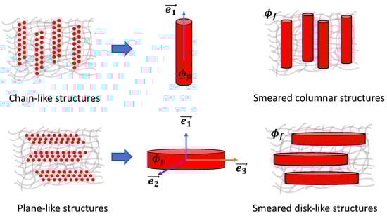
Figure 1.
Smearing of magnetic particles (total volume fraction ) into columnar and disk-like structures. is the volume fraction of magnetizable particles inside a smeared structure, and represents the volume fraction of smeared structures inside an elastomer matrix. MAEs, in both cases, exhibit transverse isotropy along a unit vector .
Following our previous works [37,38], an ellipsoidal MAE sample of two equal semi-axes and one distinct semi-axis is considered, as shown in Figure 2. We study the effect of different particle microstructures and the initial shape of an MAE sample on its mechanical properties. The magnetic particles are considered as point-like dipoles, and the linear magnetization regime is assumed. The paper is arranged as follows: In the next section, the material model of ellipsoidal MAE is presented. The simplification of the formalism presented in Ref. [53] is explained in detail by providing simple geometrical arguments. The magneto-induced deformations and magneto-rheological effects are investigated in Section 3 and Section 4, respectively. In the last section, conclusions are drawn, and the effect of particle rearrangement is discussed.
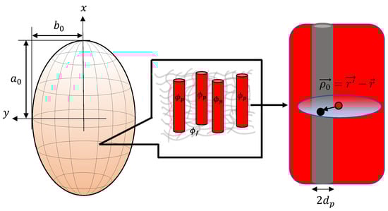
Figure 2.
The image on the left represents schematics of an MAE sample with the shape of an ellipsoid of revolution having two equal semi-axes and one distinct semi-axis . The magnified image on the right side depicts a smeared columnar structure.
2. Materials and Methods
The deformation gradient tensor is defined as , where is the position vector of a material point in the reference configuration (undeformed), and is the position vector in the current configuration (deformed). The resultant right and left Cauchy deformation tensors are , , respectively. The principal invariants of the right Cauchy deformation tensor are given as [56]
where J is the volume ratio between current and reference configurations [57]. For incompressible materials, [58]. It is a common practice to separate the elastic free energy of transversely isotropic materials into a contribution for the elasticity of the matrix material and the influence of anisotropic structures . The anisotropic part is defined with additional invariants, called “pseudo-invariants” , , and , under rotations around the preferred direction in the material. They describe the effects of reinforcement due to the presence of rigid anisotropic structures [58,59].
The chain-like structures in MAEs can be approximated as fibers [54]. In the literature [56], the fiber-reinforced elastic composites are typically modeled as transversely isotropic materials. The pseudo invariant characterizes a family of fibers with some preferred direction (for instance, along unit vector ). The invariant is only considered during the shear deformations, as shown in [59]. It is omitted for uniaxial elongation by considering a modification . For uniaxial elongation, the invariant is always zero. Similarly, the MAEs with plane-like structures are also transversely isotropic materials [54]. However, in this case, it is not possible to model the plane-like structures with only pseudo invariant , as we explain further in Section 2.2. In order to model such a microstructure, we consider additionally auxiliary pseudo invariant that describes the same family of fibers but with a different preferred direction (for example, along unit vector , and ) [56].
In this work, we restrict ourselves to uniaxial deformations. Thus, we describe the total elastic free energy density in the following form:
Furthermore, we consider the isotropic elastic part as Neo-Hookean solid. The anisotropic elastic part can be described by a variety of forms reviewed in Ref. [59]. Anisotropic MAEs with chain-like structures can be approximated as elongated columnar structures or “fibers”. Such an alternative description for chain-like structures was introduced in Ref. [53]. In this work, we extend this description to plane-like structures. Since the precise particle positions are generally unknown, we smear them continuously over some expanded microstructure; see Figure 1. We approximate the chain-like structures as smeared columns (SCs) and plane-like structures as smeared disks (SDs). The anisotropic MAEs with SCs and SDs have different anisotropic contributions to the elastic free energy and magnetic energy densities.
In the linear magnetization regime, the total magnetic energy density in the sample is given by [31,37,53]:
where NA is the permeability of vacuum. The magnetization field depends on the sample shape and the particle distribution. We consider the homogeneous external magnetic field . Then, the volume integral in Equation (4) can be written as:
where denotes the average magnetization among all inclusions in the sample. Since the elastic matrix is not magnetizable, the factor , the total volume fraction of particles, enters Equation (5).
Previous works showed that assuming an ellipsoidal sample shape, the magnetic energy can be decomposed into two independent contributions. One represents the macroscopic shape of the sample, , and the other refers to the microscopic particle distribution, [31,53]. Here, is closely related to the demagnetizing factor of a homogeneously magnetized ellipsoid. In order to model the microscopic contribution , the individual particle positions must be presumed. For example, this can be achieved considering lattice-like particle distributions [29,31,47]. However, as mentioned previously, the precise particle positions are unknown in realistic samples [53]. Furthermore, we consider constant density within smeared structures, as depicted in Figure 1. Thus, we define as the volume fraction of particles inside a smeared structure, and it follows: . The volume fraction of smeared structures (at ) is obtained as the ratio of [54]. At , the particle density is the same all over the sample describing the isotropic distribution of particles (no smeared structures) and consequently . To attain magnetic energy for samples with SCs, the locally varying magnetization field was calculated self-consistently in Ref. [53]. Such “full” self-consistent treatment requires an elaborate formulation, and the solution can be computed only numerically.
Recently, an efficient approximation scheme [41,60] could be established to calculate magnetization fields in composite materials under rather general conditions. For example, a tensorial notation was introduced to describe the effects of arbitrarily oriented external magnetic fields and/or more generic particle microstructures or sample shapes. In particular, the tensor was introduced to describe the microstructure. In the present work, we consider the external magnetic field aligned with the symmetry axis of the particle structure. Furthermore, also the symmetry axis of the sample form itself, i.e., ellipsoid of revolution, is co-aligned with . Accordingly, the tensorial notation can be reduced to a scalar description with all fields oriented along the x-direction, i.e., , and consequently also the total magnetic field (a unit vector is aligned along the x-direction). Assuming the linear magnetization regime, with isotropic susceptibility , the average magnetization in the sample is found via the leading order approximation [41,60] as:
Here, denotes the effective susceptibility, with being the particle demagnetization factor. Considering spherical inclusions, we have . The macroscopic contribution from the sample shape for ellipsoidal MAEs reads , where is the demagnetizing factor of an ellipsoid along its symmetry axis [37]. According to Refs. [53,60], the contribution due to microscopic particle structure is formally obtained as:
Here, denotes a mesoscopic portion of the sample where the local particle structure is resolved, i.e., a representative volume in form of a mesoscopic sphere [53,60]. Since in the present approach, we describe the particle distribution as continuous (locally varying) fields, Equation (7) is formulated in terms of integrals instead of discrete summations over explicit particle positions. The particles are assumed to be of spherical shape with diameter and, accordingly, the Heavyside step function is introduced to restrict the integration to positions outside of the particle located at (no self-interaction of particle positions) [53,60]. Thus, from Equations (5)–(7), the magnetic energy density is
where [38]. The total free energy density of anisotropic MAEs is now a combination of three contributions: , , and . As mentioned previously, by considering the isotropic elastic part as Neo-Hookean solid, the total free energy density can be given as
Here, is the effective shear modulus of an isotropic MAE, and is the hydrodynamic reinforcement factor [61,62] obtained via the rule of mixtures (see Appendix A).
where is the shear modulus of a pure elastomer matrix. Equation (9) represents a general form of the free energy density of anisotropic MAEs. One needs to choose the appropriate form of depending on the microstructure under consideration. The values of the dimensionless parameter also change with respect to the particle distribution. In the following section, we derive the specific form of and for MAEs with SCs and SDs.
2.1. Free Energy of Anisotropic MAEs with Smeared Columns
Anisotropic MAEs with SCs can be approximated as fiber-reinforced materials that exhibit unidirectional anisotropy along the fibers. For such materials, we consider a quadratic form of as given in Ref. [59].
where the dimensionless parameter describes the fiber (smeared column) stretch. In this case, is invariant under the rotations around a unit vector , as shown in Figure 1. Thus,
The SCs are all aligned in the same direction, and thus, they are described by only one pseudo-invariant (thus, here, ). The longitudinal elastic modulus of MAEs with SCs along the symmetry axis is larger than the elastic modulus in the transverse direction. We compare the longitudinal elastic modulus derived from the elastic free energy of anisotropic MAEs having SCs with the modulus predicted from the rule of the mixtures to obtain values of the dimensionless parameter ; for details, see Appendix B. For MAEs with SCs,
where k is also the hydrodynamic reinforcement factor [61,62] given as
where is the shear modulus of the isotropic fiber/smeared column. In the present formulation, an isotropic distribution is realized when , and consequently . Thus, one obtains following relations:
In Ref. [53], the form of for columnar structures has been studied in detail. There, a self-consistent treatment with locally varying magnetization within the microstructure is derived. Here, we aim to provide an approximate, but in return, analytic form for the microstructure effect. In the following, we make use of some relations provided in Ref. [53]. We note that in smeared structures along , the local particle volume fraction does not depend on the x-coordinate . Then, the contributions to originating from material portions situated at finite lateral distances (-directions) with respect to the reference location, i.e., position in Equation (7), vanish. A non-zero contribution results from particles found above and below the reference particle i, see Figure 2, and we denote it as . Another non-zero contribution relates to volume portions located sufficiently far away so that the micro-structure is not resolvable anymore and the particle distribution appears homogeneous with . The corresponding share to evaluates to [53].
In order to calculate the contribution , we neglect effects due to particles located exactly on or close to the boundaries of a smeared column. Neglecting such ‘boundary’ effects has the beneficial outcome that , and thus altogether, adopts a very simple analytic form. Accounting for the boundaries of particle-containing columns results in an explicit dependency on the actual lateral size, or diameter, of the columns. Upon introducing the elastic free energy, we describe the mechanical effect of particle microstructures in terms of fiber-like structures with enhanced stiffness parameter . The formulation is restricted to the parameters and . No dependency on the thickness of the smeared columns is presumed. Accordingly, neglecting such structural size effects in the magnetic formulation represents a consistent simplification. Assuming any reference particle positioned well inside the columnar structure, and considering the particle volume fraction in such column as constant with , we note that every particle experiences an identical filler concentration above and below its actual position. Consequently, the contribution is calculated as [53]
and the total in the case of SCs reads:
This expression is remarkably neat and compact. Note that Equation (17) correctly reproduces the result for an isotropic particle distribution, i.e., at [31,41,63]. The formation of columnar structures requires and in turn, [31,41,63]. By substituting Equations (11) and (17) into (9), we obtain
Equation (18) refers to the specific form of the free energy density of anisotropic MAEs with SCs.
2.2. Free Energy of Anisotropic MAEs with Smeared Disks
We consider the plane-like microstructure of MAEs as smeared disks, as shown in Figure 1. In this case, too, MAEs exhibit transverse isotropy along the symmetry axis of SDs. However, SDs require at least two invariants to describe the plane of isotropy, which is perpendicular to a unit vector . Thus, here, we consider two pseudo invariants and to take into account the anisotropic contribution due to SDs to the elastic free energy of MAEs. We define and with respect to unit vectors and as
The unit vectors and are perpendicular to each other and also to the direction of anisotropy such that and , as shown in Figure 1. The invariants and are typically used in the modeling of transversely isotropic materials with two families of fibers. In this work, we consider a disk (or plane) formed by a single family of fibers but with directions along and , retaining the preferred direction the same as in the previous case (along ). As the SD has uniform properties around its symmetry axis, the mathematical manipulation of considering two directions such that does not lead to orthotropic materials [56], keeping the material transversely isotropic. By considering the quadratic form of and , we propose the following anisotropic contribution of SDs
where is related to the stretch of SDs in anisotropic MAEs. Unlike in the previous sections, MAEs with SDs have larger transverse modulus in the plane perpendicular the symmetry axis () and smaller along this axis. In this case, we compare the transverse modulus calculated from the free energy of MAEs with SDs using Equation (20) to the modulus obtained from the rule of mixtures to estimate the value of (see Appendix C for more details). Here, an analytical expression for is not possible, and the solution is calculated numerically. With the proposed for MAEs with SDs, one can attain total elastic free energy density. Analogous to Equation (15), we have
The contribution of SDs to magnetic energy density also differs from the previous case of MAEs with SCs. The prefactor for SCs in Equation (17) can be easily understood from geometrical considerations. Smeared columns may be interpreted as infinitely long cylinders or as prolate spheroids with an infinitely large aspect ratio . The demagnetizing factor along such spheroid reads , and the shape factor becomes . Analogously, we may describe smeared disks as infinitely expanded oblate spheroids with vanishing . The demagnetizing factor for such objects turns to , and consequently, we immediately find:
3. Magneto-Induced Deformations
The tensile mechanical test is a destructive process that characterizes the tensile strength and the extent to which the sample elongates [64]. In the case of MAE, the tensile tests are carried out in the presence of an external magnetic field . This section investigates the magneto-induced elongation of anisotropic MAEs for different volume fractions of magnetic particles. The unit vector and applied magnetic field are aligned along the x-axis, as shown in Figure 3. The uniaxial deformation gradient tensor in matrix form can be given as
where and are the stretch ratios along the , and z-directions, respectively. The incompressibility condition states:
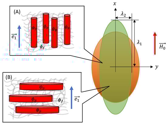
Figure 3.
Uniaxial deformation of an ellipsoidal MAE sample with different microstructures. The orange-coloured MAE sample represents the reference configuration, while the green-coloured sample depicts the deformed configuration. is the volume fraction of magnetizable particles inside a smeared structure, and represents the volume fraction of smeared structures inside an elastomer matrix. (A) SC microstructure and (B) SD microstructure.
The demagnetizing factor of an ellipsoid along its symmetry axis is a function of aspect ratios and . The change in aspect ratio is governed by the applied loading (mechanical or magnetic loadings) as:
where is the initial aspect ratio of a spheroidal MAE sample; see Figure 2. Accordingly, the demagnetizing factor is a function of the deformation gradient tensor F. We choose the value of magnetic susceptibility to model highly magnetizable material such as carbonyl iron with [10,31,53]. As the linear magnetization regime is assumed, we restrict the magnitude of applied magnetic field to a maximum value of 470 kA/m. A very soft elastomer matrix of shear modulus kPa is considered [46] to achieve maximum field-induced effects. All these parameters are summarized in Table 1.

Table 1.
The values of parameters used in the numerical calculations.
With the deformation gradient tensor F and Equation (9), the Cauchy stress tensor of the MAE in the general case reads:
Note that does not depend on the actual size of a smeared structure. Thus, the microstructure deformation is neglected (). In the following sections, we investigate the magneto-induced elongations and magneto-rheological effects of MAEs with SCs and SDs. Accordingly, we substitute the expressions of and in Equation (27).
3.1. Smeared Columns
Here, we examine the uniaxial elongation of anisotropic MAEs with SCs under the application of an external magnetic field, as shown in Figure 3. We apply the external magnetic field along the symmetry axis of a spheroidal MAE sample of the initial aspect ratio and calculate the magneto-induced elongation in the applied field direction. For SCs, the values of dimensionless parameters and are positive and given by Equations (13) and (17), respectively. By substituting Equations (11) and (17) into (27), the corresponding Cauchy stress components can be calculated as:
where and . To calculate the magneto-induced elongation, we consider . From incompressibility condition (25) and Equation (30), we receive the relationship between the stretch ratios and the hydrostatic pressure p
Thus, the non-zero Cauchy stress component along the symmetry axis of an MAE sample is
The stretch ratio in Equation (32) is a total stretch [37] combining: (1) a stretch due to the applied magnetic field and (2) a stretch due to external mechanical loadings . In this section, we consider purely magnetic loadings. Hence, . The magneto-induced (equilibrium) elongation is calculated at equilibrium condition when . Figure 4 shows the magneto-induced elongation of an MAE with SC microstructure as a function of the initial aspect ratio and the volume fraction of particles inside a smeared column at different total volume fractions . The equilibrium elongation decreases with an increase in at constant total particle volume fraction . The volume fraction inside an elongated column is directly related to the column’s strength. Consequently, the dimensionless parameter is strongly increasing as . Furthermore, the strengthening of columns, especially when , outweighs the magnetic field effect. As a result, magneto-induced elongation reduces. The optimal initial aspect ratio , where the maximum magneto-induced elongation is predicted, shifts toward higher values with an increase in and an overall decrease in the magnitude of (for example, refer to Figure S1A in the Supporting Information).
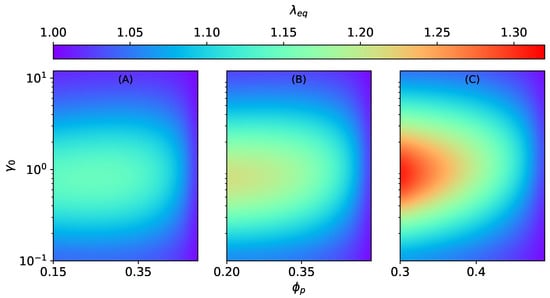
Figure 4.
The magneto-induced elongation for MAEs with SC microstructure as a function of the initial aspect ratio and the volume fraction at constant kA/m, kPa. (A) , (B) , (C) .
3.2. Smeared Disks
For MAEs with SDs, the value of the dimensionless parameter is negative while is positive. The Cauchy stress components for MAEs with SDs are derived from Equations (20), (22) and (27) as
Similar to the previous case, here, , and the relationship between stretch ratios and the hydrostatic pressure p is given by Equation (31). Thus, the non-zero Cauchy stress component along the field direction for MAEs with SDs is
The effect of and on the magneto-induced elongation of MAEs with SD structures is investigated as a function of the initial aspect ratio . Analogous to SC structures, the equilibrium elongation decreases with an increase in the values of at constant , as seen in Figure 5. Here also, as , the dimensionless parameter becomes very high, which results in the overall decrease in the magneto-induced elongations. In contrast to the previous section, in this case, the shifting of maxima is negligible, as illustrated in the Supporting Information; see Figure S1B. Both SCs and SDs lead to an overall elongation of an MAE sample. It is because the surrounding columns and disks do not interact, and the shape effect is dominant. In addition, the elongation is more pronounced for SCs () than SDs () because the magnetic energy increases with an increase in ; see Equation (8). Nevertheless, when , the elastic parameters and dominate the effect of the applied magnetic field.
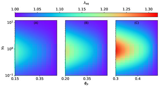
Figure 5.
The magneto-induced elongation for MAEs with SD microstructure as a function of the initial aspect ratio and the volume fraction at constant kA/m, kPa. (A) , (B) , (C) .
4. Magneto-Rheological Effect
The magneto-rheological effect (MR) is defined as the change in the elastic moduli of the MAE in the presence of an external magnetic field [37]. The initial shape of an MAE sample affects the MR effect significantly, as already shown in our previous works [37,38]. Here, along with the initial shape, we also study the effect of different microstructures (SCs and SDs).
4.1. Smeared Columns
The longitudinal elastic modulus of an ellipsoidal MAE sample with SCs in the presence of an external magnetic field is calculated by taking the derivative of the Cauchy stress component over the stretch ratio at . Similarly, the transverse Cauchy stress component is needed to calculate the MR effect perpendicular to the field direction. For that, we consider a uniaxial elongation applied perpendicular to the field direction. Thus, in this case, . From the incompressibility condition (25) and Equations (30), the stretch relation is given as:
Here, , where . Considering the stretch relation in Equation (35), we derive the transverse Cauchy stress component
The expression for transverse elastic modulus () is obtained by taking the derivative of Equation (36) over . The elastic modulus () is calculated at and . Thus, the elastic moduli (at ) of MAEs with SC microstructure are given as:
The % MR-effect of MAEs with SCs is calculated as
Similar to isotropic MAEs [37], the MR effect of anisotropic MAEs with SC microstructure is positive along the field direction and is negative transverse to it, as illustrated in Figure 6 and Figure 7. The MR effect along the field direction for SC microstructure increases with the volume fraction of particles inside a smeared structure for different total volume fractions (, , ). However, after a critical value of , irrespective of the total volume fraction , the effects begin to vanish, as seen in Figure 6. It is the consequence of an increase in the effective elastic modulus of an elastomer composite due to higher values of when .
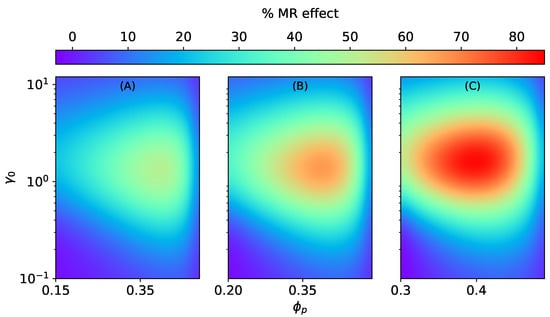
Figure 6.
The magneto-rheological effect of an ellipsoidal MAE with SC microstructure stretched along the field direction at constant = 470 kA/m, kPa. (A) , (B) , (C) .
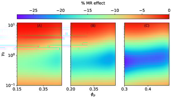
Figure 7.
The magneto-rheological effect of an ellipsoidal MAE with an SC microstructure stretched perpendicular to the field direction at constant = 470 kA/m, kPa. (A) , (B) , (C) .
4.2. Smeared Disks
In this case, to calculate the longitudinal elastic modulus of MAEs with SDs, we use . Analogous to the previous section, to calculate the transverse Cauchy stress component , we consider a uniaxial elongation applied perpendicular to the field direction. Thus, as explained previously, . From the incompressibility condition (25) and Equation (33), the stretch relation for MAEs with SDs is given as:
where . Note that again , and . Thus, the transverse Cauchy stress component is
By substituting the Cauchy stress components and in Equation (37), we obtain the elastic moduli and consequently the relative MR effects and of MAEs with SDs.
Contrary to MAEs with SCs, the magnitude of MR effects and decrease monotonically with , as shown in Figure 8 and Figure 9. The longitudinal MR effect can even change sign and become negative for higher values of and oblate shapes; see Figure 8B,C. Similarly to magneto-induced elongation, in the case of MR effects, too, the shifting of maxima can be seen in Figures S2 and S3 in the Supporting Information. For MR effects along the field direction in both cases (SCs and SDs), the optimal value of the initial aspect ratio shifts toward smaller values with increasing . On the other hand, for MR effects perpendicular to the field direction (SCs and SDs), the maxima shifts toward higher values of with an increase in .
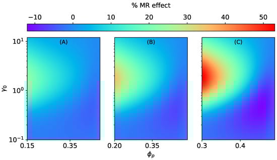
Figure 8.
The magneto-rheological effect of an ellipsoidal MAE with SD microstructure stretched along the field direction at constant = 470 kA/m, kPa. (A) , (B) , (C) .
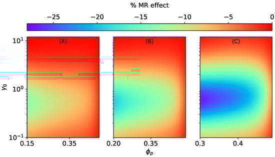
Figure 9.
The magneto-rheological effect of an ellipsoidal MAE with SD microstructure stretched perpendicular to the field direction at constant = 470 kA/m, kPa. (A) , (B) , (C) .
5. Discussion
In the present work, we illustrated the effect of the microstructure on the mechanical properties of ellipsoidal magnetoactive elastomers. By extending the previous approach [53] to describe the distribution of magnetic particles, a much simplified analytical expression is derived depicting the chain-like and plane-like microstructures as smeared columns and disks, respectively. The proposed expression for reproduces accurate results [31,41,63] for an isotropic particle distribution, , for a chain-like microstructure, , and a plane-like microstructure, . The formalism presented in Equation (9), where the shape factor and the microstructure description , allows us to simultaneously study the effect of the initial shape of an MAE sample and the initial particle distribution. The optimum values of the volume fraction of particles inside a smeared structure , where the MR effect is maximal, are obtained as a function of the initial aspect ratio and the total volume fraction of magnetic particles . The effect of the microstructure shows an increase in the field-dependent modulus in the case of SCs. Yet, it is a small enhancement compared to isotropic MAEs and the enhancement reported in experimental studies [65].
The critical value of seen in Figure 6 directly points toward the overall increase in the effective elastic modulus of an MAE sample due to the consideration of smeared columns. According to [66,67,68], the application of an external magnetic field leads to restructuring of the particle arrangement in MAEs. Thus, one can consider the particle microstructure starting from the isotropic distribution, which changes to form smeared columns in the presence of an external magnetic field. The formation of smeared columns highly depends on the strength and orientation of an applied magnetic field as well as on the initial shear modulus of the elastomer matrix [69]. In that case, our model predicts a very high MR effect (14 fold), as depicted in Figure 10, by assuming the formation of smeared columns. It shows the large enhancement of the elastic modulus, where a major contribution arises from the elastic free energy density in addition to the field-induced stiffening. In this MR effect, the hydrodynamic reinforcement factor k plays a key role. The factor k diverges at , at which the drastic increase in the MR effect is realized, as shown in Figure 10. The divergence of k is exactly equivalent to the percolation threshold defined in Ref. [66]. The analysis presented in this work provides an approximate but promising hypothesis to understand the reasoning behind the huge (over several orders of magnitude) MR effects seen in experimental studies [70]. In conclusion, the present work covers the entire spectrum of MAEs ranging from chain-like to plane-like microstructure, including the isotropic particle distribution. The proposed model shows the ability to predict the uniaxial magneto-mechanical behavior of MAEs with remarkable consistency between different microstructures.
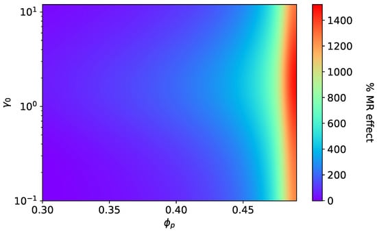
Figure 10.
The magneto-rheological effect: Transition of isotropic MAE to anisotropic MAE with smeared columns at = 470 kA/m, kPa, .
Supplementary Materials
The following are available at https://www.mdpi.com/article/10.3390/ma15020645/s1, Figure S1: The magneto-induced elongations of anisotropic MAEs as a function of the initial aspect ratio at different volume fractions and . (A) For smeared columns, (B) for smeared disks. Figure S2: The magneto-rheological effect of anisotropic MAEs with SCs as a function of the initial aspect ratio at different volume fractions and . (A) The MR effect along , (B) The MR effect perpendicular to . Figure S3: The magneto-rheological effect of anisotropic MAEs with SDs as a function of the initial aspect ratio at different volume fractions and . (A) The MR effect along , (B) The MR effect perpendicular to .
Author Contributions
Conceptualization, D.R. and S.C.; methodology, M.S.; formal analysis, S.C.; investigation, S.C.; writing—original draft preparation, S.C.; writing—review and editing, D.R and M.S.; supervision, M.S.; project administration, D.R.; funding acquisition, M.S. All authors have read and agreed to the published version of the manuscript.
Funding
The DFG research project 380321452/GRK2430 is supported by the Deutsche Forschungsgemeinschaft (DFG, German Research Foundation).
Institutional Review Board Statement
Not applicable.
Informed Consent Statement
Not applicable.
Data Availability Statement
On inquiry, the data presented in this study is available from the authors.
Acknowledgments
The financial support by Deutsche Forschungsgemeinschaft is gratefully acknowledged.
Conflicts of Interest
The authors declare no conflict of interest.
Appendix A. The Rule of Mixtures
The anisotropic MAEs behave as transversely isotropic materials already in the absence of an external magnetic field. Such materials are characterized with the help of five independent material parameters. The five material parameters include two elastic moduli (longitudinal and transverse), two shear moduli (longitudinal and transverse), and a major Poisson’s ratio. For an incompressible MAE, the Poisson’s ratio is 0.5. A simplified approach is proposed by Chen et al. [71] to calculate the effective elastic properties of anisotropic MAEs. In this approach, the microstructure in MAEs is approximated as fiber-like structures. The shear modulus of the fiber is calculated using the Pade approximation [72] as with
where k is referred to as the hydrodynamic reinforcement factor [61,62], as described in Section 2. Then, the effective shear modulus of the MAE with isotropic particle distribution is calculated by setting , where is the total volume fraction of magnetic particles inside the elastomer matrix ( at ). Equation (A1) diverges at ; therefore, the values of are bound to . The fiber is assumed to be isotropic, and the effective elastic modulus can be easily obtained from Equation (A1) as . According to the rule of mixtures, we calculate the effective longitudinal elastic modulus of an anisotropic MAE as
where is the elastic modulus of isotropic matrix. Similarly, the inverse rule of mixtures provides the transverse elastic modulus as
As shown in Figure 3, we consider that smeared columns lie parallel, and the smeared disks lie perpendicular to the symmetry axis (x-axis) of a spheroidal MAE sample. Thus, for smeared disk structures, the longitudinal and transverse elastic moduli should be interchanged.
Appendix B. The Estimation of
In the absence of an external magnetic field, the elastic Cauchy stress components of MAEs with SCs can be obtained from Equation (27) by taking as
In the case of uniaxial elongation along the x-direction, . From the incompressibility condition (25) and Equation (A4), the relation between stretch ratios can be derived
The Cauchy stress component of MAEs along the symmetry axis in the absence of an external magnetic field is
The corresponding elastic modulus along the x-axis is calculated by taking the derivative of the Cauchy stress component over the stretch ratio at .
In this case, we receive an analytical expression for the effective elastic modulus as a function of the dimensionless parameter . During uniaxial elongation along the y-direction, . From the incompressibility condition (25) and Equation (A4), the relation between stretch ratios can be derived as:
The transverse elastic Cauchy stress component is
The corresponding transverse elastic modulus can be obtained by taking the derivative of Equation (A9) over the stretch ratio at using relation (A8).
Here, unlike , only a numerical solution is possible for the transverse elastic modulus . To extract the values of the dimensionless parameter , we equate Equations (A7) and (A2) and receive expression (13) in the main text. The longitudinal and transverse elastic moduli of MAEs with SCs in the absence of an external magnetic field as a function of are shown in Figure A1A.
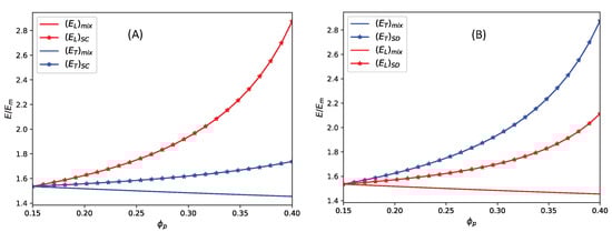
Figure A1.
The elastic moduli comparison from mixture rule and elastic free energy. (A) For smeared columns, (B) for smeared disks.
Appendix C. The Estimation of
Similar to Appendix A, the elastic Cauchy stress components of MAEs with SDs as obtained from Equation (27) are
Using the incompressibility condition (25), the elastic Cauchy stress component along the symmetry axis of MAEs with SDs is
The corresponding elastic modulus along the symmetry axis is
The transverse elastic Cauchy stress component and corresponding elastic modulus are
In this case, to calculate the values of a dimensionless parameter , we equate Equations (A2) and (A15). In Figure A1, the elastic moduli obtained from the rule of the mixtures and calculated through the proposed elastic free energy are plotted as a function of . By comparing (A7) and (A15) with (A2), we obtain the values of and , respectively. Thus, the elastic moduli, obtained from the rule of mixtures, and exactly match with and . In contrast, a deviation can be seen in the other two cases, as shown in Figure A1. According to the rule of mixtures, the longitudinal modulus of MAEs with SCs is always greater, and the transverse modulus is always less than the isotropic elastic modulus. It is exactly the opposite (exchange and ) in the case of smeared disks. On the other hand, the free energy density of transversely isotropic materials is typically formulated in such a way that the longitudinal modulus (for MAEs with SCs) is always greater than the transverse modulus, and both moduli are greater than the isotropic elastic modulus (and vice versa in the case of SDs).
References
- Dorfmann, A.; Ogden, R.W. Magnetoelastic modelling of elastomers. Eur. J. Mech. A/Solids 2003, 22, 497–507. [Google Scholar] [CrossRef]
- Dorfmann, A.; Ogden, R.W. Nonlinear magnetoelastic deformations of elastomers. Acta Mech. 2004, 167, 13–28. [Google Scholar] [CrossRef]
- Zhou, G.Y.; Jiang, Z.Y. Deformation in magnetorheological elastomer and elastomer-ferromagnet composite driven by a magnetic field. Smart Mater. Struct. 2004, 13, 309–316. [Google Scholar] [CrossRef]
- Filipcsei, G.; Abramchuk, S.; Kramarenko, E.; Stepanov, G.; Nikitin, L.V.; Khokhlov, A.R.; Zrınyi, M. Novel highly elastic magnetic materials for dampers and seals: Part I. Preparation and characterization of the elastic materials. Polym. Adv. Technol. 2007, 18, 883–890. [Google Scholar] [CrossRef]
- Stepanov, G.V.; Kramarenko, E.Y.; Semerenko, D.A. Magnetodeformational effect of the magnetoactive elastomer and its possible applications. J. Phys. Conf. Ser. 2013, 412. [Google Scholar] [CrossRef]
- Sorokin, V.V.; Ecker, E.; Stepanov, G.V.; Shamonin, M.; Monkman, G.J.; Kramarenko, E.Y.; Khokhlov, A.R. Experimental study of the magnetic field enhanced Payne effect in magnetorheological elastomers. Soft Matter 2014, 10, 8765–8776. [Google Scholar] [CrossRef] [PubMed]
- Li, Y.; Li, J.; Li, W.; Du, H. A state-of-the-art review on magnetorheological elastomer devices. Smart Mater. Struct. 2014, 23, 123001. [Google Scholar] [CrossRef]
- Sutrisno, J.; Purwanto, A.; Mazlan, S.A. Recent progress on magnetorheological solids: Materials, fabrication, testing, and applications. Adv. Eng. Mater. 2015, 17, 563–597. [Google Scholar] [CrossRef]
- Becker, T.I.; Böhm, V.; Chavez Vega, J.; Odenbach, S.; Raikher, Y.L.; Zimmermann, K. Magnetic-field-controlled mechanical behavior of magneto-sensitive elastomers in applications for actuator and sensor systems. Arch. Appl. Mech. 2019, 89, 133–152. [Google Scholar] [CrossRef]
- Saveliev, D.V.; Belyaeva, I.A.; Chashin, D.V.; Fetisov, L.Y.; Romeis, D.; Kettl, W.; Kramarenko, E.Y.; Saphiannikova, M.; Stepanov, G.V.; Shamonin, M. Giant extensional strain of magnetoactive elastomeric cylinders in uniform magnetic fields. Materials 2020, 13, 3927. [Google Scholar] [CrossRef]
- Hines, L.; Petersen, K.; Lum, G.Z.; Sitti, M. Soft Actuators for Small-Scale Robotics. Adv. Mater. 2017, 29, 1603483. [Google Scholar] [CrossRef]
- Yu, K.; Fang, N.X.; Huang, G.; Wang, Q. Magnetoactive Acoustic Metamaterials. Adv. Mater. 2018, 30, 1706348. [Google Scholar] [CrossRef] [PubMed]
- Chung, H.; Parsons, A.M.; Zheng, L. Magnetically Controlled Soft Robotics Utilizing Elastomers and Gels in Actuation: A Review. Adv. Intell. Syst. 2021, 3, 2000186. [Google Scholar] [CrossRef]
- Allocca, L.; Davino, D.; Montanaro, A.; Visone, C. Proof of principle of a fuel injector based on a magnetostrictive actuator. Actuators 2021, 10, 237. [Google Scholar] [CrossRef]
- Rus, D.; Tolley, M.T. Design, fabrication and control of soft robots. Nature 2015, 521, 467–475. [Google Scholar] [CrossRef] [Green Version]
- Zhao, X.; Kim, J.; Cezar, C.A.; Huebsch, N.; Lee, K.; Bouhadir, K.; Mooney, D.J. Active scaffolds for on-demand drug and cell delivery. Proc. Natl. Acad. Sci. USA 2011, 108, 67–72. [Google Scholar] [CrossRef] [PubMed] [Green Version]
- Bastola, A.K.; Hossain, M. The shape—Morphing performance of magnetoactive soft materials performance. Mater. Des. 2021, 211, 110172. [Google Scholar] [CrossRef]
- Yarali, E.; Baniasadi, M.; Zolfagharian, A.; Chavoshi, M.; Arefi, F.; Hossain, M.; Bastola, A.; Ansari, M.; Foyouzat, A.; Dabbagh, A.; et al. Magneto-/electro-responsive polymers toward manufacturing, characterization, and biomedical/soft robotic applications. Appl. Mater. Today 2022, 26, 101306. [Google Scholar] [CrossRef]
- Wu, S.; Hu, W.; Ze, Q.; Sitti, M.; Zhao, R. Multifunctional magnetic soft composites: A review. Multifunct. Mater. 2020, 3, 4. [Google Scholar] [CrossRef]
- Alekhina, Y.A.; Makarova, L.A.; Kostrov, S.A.; Stepanov, G.V.; Kazimirova, E.G.; Perov, N.S.; Kramarenko, E.Y. Development of magnetoactive elastomers for sealing eye retina detachments. J. Appl. Polym. Sci. 2019, 136, 47425. [Google Scholar] [CrossRef]
- Bira, N.; Dhagat, P.; Davidson, J.R. A Review of Magnetic Elastomers and Their Role in Soft Robotics. Front. Robot. AI 2020, 7, 146. [Google Scholar] [CrossRef]
- Cantera, M.A.; Behrooz, M.; Gibson, R.F.; Gordaninejad, F. Modeling of magneto-mechanical response of magnetorheological elastomers (MRE) and MRE-based systems: A review. Smart Mater. Struct. 2017, 26, 023001. [Google Scholar] [CrossRef]
- Ginder, J.M.; Schlotter, W.F.; Nichols, M.E. Magnetorheological elastomers in tunable vibration absorbers. In Smart Structures and Materials 2001: Damping and Isolation; Inman, D.J., Ed.; International Society for Optics and Photonics: Bellingham, WA, USA, 2001; Volume 4331, pp. 103–110. [Google Scholar] [CrossRef]
- Gu, H.; Lee, S.W.; Carnicelli, J.; Zhang, T.; Ren, D. Magnetically driven active topography for long-term biofilm control. Nat. Commun. 2020, 11, 2211. [Google Scholar] [CrossRef]
- Yin, H.M.; Sun, L.Z.; Chen, J.S. Magneto-elastic modeling of composites containing chain-structured magnetostrictive particles. J. Mech. Phys. Solids 2006, 54, 975–1003. [Google Scholar] [CrossRef]
- Davis, L.C. Model of magnetorheological elastomers. J. Appl. Phys. 1999, 85, 3348–3351. [Google Scholar] [CrossRef]
- Kalina, K.A.; Metsch, P.; Kästner, M. Microscale modeling and simulation of magnetorheological elastomers at finite strains: A study on the influence of mechanical preloads. Int. J. Solids Struct. 2016, 102–103, 286–296. [Google Scholar] [CrossRef]
- Jolly, M.R.; Carlson, J.D.; Muñoz, B.C.; Bullions, T.A. The magnetoviscoelastic response of elastomer composites consisting of ferrous particles embedded in a polymer matrix. J. Intell. Mater. Syst. Struct. 1996, 7, 613–622. [Google Scholar] [CrossRef]
- Ivaneyko, D.; Toshchevikov, V.P.; Saphiannikova, M.; Heinrich, G. Magneto-sensitive elastomers in a homogeneous magnetic field: A regular rectangular lattice model. Macromol. Theory Simul. 2011, 20, 411–424. [Google Scholar] [CrossRef] [Green Version]
- Han, Y.; Hong, W.; Faidley, L.E. Field-stiffening effect of magneto-rheological elastomers. Int. J. Solids Struct. 2013, 50, 2281–2288. [Google Scholar] [CrossRef] [Green Version]
- Ivaneyko, D.; Toshchevikov, V.; Saphiannikova, M.; Heinrich, G. Mechanical properties of magneto-sensitive elastomers: Unification of the continuum-mechanics and microscopic theoretical approaches. Soft Matter 2014, 10, 2213–2225. [Google Scholar] [CrossRef] [Green Version]
- Shinoda, H.; Azukizawa, S.; Maeda, K.; Tsumori, F. Bio-Mimic Motion of 3D-Printed Gel Structures Dispersed with Magnetic Particles. J. Electrochem. Soc. 2019, 166, B3235–B3239. [Google Scholar] [CrossRef]
- Zhalmuratova, D.; Chung, H.J. Reinforced Gels and Elastomers for Biomedical and Soft Robotics Applications. ACS Appl. Polym. Mater. 2020, 2, 1073–1091. [Google Scholar] [CrossRef]
- Pierce, C.D.; Willey, C.L.; Chen, V.W.; Hardin, J.O.; Berrigan, J.D.; Juhl, A.T.; Matlack, K.H. Adaptive elastic metastructures from magneto-active elastomers. Smart Mater. Struct. 2020, 29, 065004. [Google Scholar] [CrossRef]
- Diguet, G.; Beaugnon, E.; Cavaillé, J.Y. Shape effect in the magnetostriction of ferromagnetic composite. J. Magn. Magn. Mater. 2010, 322, 3337–3341. [Google Scholar] [CrossRef]
- Yaremchuk, D.; Toshchevikov, V.; Ilnytskyi, J.; Saphiannikova, M. Magnetic energy and a shape factor of magneto-sensitive elastomer beyond the point dipole approximation. J. Magn. Magn. Mater. 2020, 513, 167069. [Google Scholar] [CrossRef]
- Chougale, S.; Romeis, D.; Saphiannikova, M. Transverse isotropy in magnetoactive elastomers. J. Magn. Magn. Mater. 2021, 523, 167597. [Google Scholar] [CrossRef]
- Chougale, S.; Romeis, D.; Saphiannikova, M. Field-induced transversely isotropic shear response of ellipsoidal magnetoactive elastomers. Materials 2021, 14, 3958. [Google Scholar] [CrossRef]
- Hu, Y.; Wang, Y.L.; Gong, X.Q.; Gong, X.L.; Zhang, X.Z.; Jiang, W.Q.; Zhang, P.Q.; Chen, Z.Y. Magnetorheological elastomers based on polyurethane/Si-rubber hybrid. Int. J. Mod. Phys. B 2005, 19, 1114–1120. [Google Scholar] [CrossRef]
- Romeis, D.; Metsch, P.; Kästner, M. Theoretical models for magneto-sensitive elastomers: A comparison between continuum and dipole approaches. Phys. Rev. E-Stat. Nonlinear Soft Matter Phys. 2017, 95, 042501. [Google Scholar] [CrossRef]
- Romeis, D.; Kostrov, S.A.; Kramarenko, E.Y.; Stepanov, G.V.; Shamonin, M.; Saphiannikova, M. Magnetic-field-induced stress in confined magnetoactive elastomers. Soft Matter 2020, 16, 9047–9058. [Google Scholar] [CrossRef]
- Hintze, C.; Borin, D.Y.; Ivaneyko, D.; Toshchevikov, V.; Saphiannikova-Grenzer, M.; Heinrich, G. Soft magnetic elastomers with controllable stiffness: Experiments and modelling. KGK Kautsch. Gummi Kunststoffe 2014, 67, 53–59. [Google Scholar]
- Wei, B.; Gong, X.; Jiang, W. Influence of polyurethane properties on mechanical performances of magnetorheological elastomers. J. Appl. Polym. Sci. 2010, 116, 771–778. [Google Scholar] [CrossRef] [Green Version]
- Winger, J.; Schümann, M.; Kupka, A.; Odenbach, S. Influence of the particle size on the magnetorheological effect of magnetorheological elastomers. J. Magn. Magn. Mater. 2019, 481, 176–182. [Google Scholar] [CrossRef]
- Borin, D.; Stepanov, G.; Musikhin, A.; Zubarev, A.; Bakhtiiarov, A.; Storozhenko, P. Magnetorheological effect of magnetoactive elastomer with a permalloy filler. Polymers 2020, 12, 2371. [Google Scholar] [CrossRef]
- Kostrov, S.A.; Dashtimoghadam, E.; Keith, A.N.; Sheiko, S.S.; Kramarenko, E.Y. Regulating Tissue-Mimetic Mechanical Properties of Bottlebrush Elastomers by Magnetic Field. ACS Appl. Mater. Interfaces 2021, 13, 38783–38791. [Google Scholar] [CrossRef]
- Ivaneyko, D.; Toshchevikov, V.; Saphiannikova, M.; Heinrich, G. Effects of particle distribution on mechanical properties of magneto-sensitive elastomers in a homogeneous magnetic field. Condens. Matter Phys. 2012, 15, 1–12. [Google Scholar] [CrossRef] [Green Version]
- Danas, K.; Kankanala, S.V.; Triantafyllidis, N. Experiments and modeling of iron-particle-filled magnetorheological elastomers. J. Mech. Phys. Solids 2012, 60, 120–138. [Google Scholar] [CrossRef]
- Javili, A.; Chatzigeorgiou, G.; Steinmann, P. Computational homogenization in magneto-mechanics. Int. J. Solids Struct. 2013, 50, 4197–4216. [Google Scholar] [CrossRef]
- Han, Y.; Mohla, A.; Huang, X.; Hong, W.; Faidley, L.E. Magnetostriction and field stiffening of magneto-active elastomers. Int. J. Appl. Mech. 2015, 7, 1550001. [Google Scholar] [CrossRef] [Green Version]
- Metsch, P.; Kalina, K.A.; Spieler, C.; Kästner, M. A numerical study on magnetostrictive phenomena in magnetorheological elastomers. Comput. Mater. Sci. 2016, 124, 364–374. [Google Scholar] [CrossRef]
- Dohmen, E.; Kraus, B. Coupled anisotropic magneto-mechanical material model for structured magnetoactive materials. Polymers 2020, 12, 2710. [Google Scholar] [CrossRef]
- Romeis, D.; Toshchevikov, V.; Saphiannikova, M. Elongated micro-structures in magneto-sensitive elastomers: A dipolar mean field model. Soft Matter 2016, 12, 9364–9376. [Google Scholar] [CrossRef]
- Ivaneyko, D.; Toshchevikov, V.; Saphiannikova, M. Dynamic-mechanical behaviour of anisotropic magneto-sensitive elastomers. Polymer 2018, 147, 95–107. [Google Scholar] [CrossRef]
- Kumar, V.; Lee, D.J. Iron particle and anisotropic effects on mechanical properties of magneto-sensitive elastomers. J. Magn. Magn. Mater. 2017, 441, 105–112. [Google Scholar] [CrossRef]
- Holzapfel, G.A. Nonlinear Solid Mechanics; John Wiley & Sons Ltd.: Hoboken, NJ, USA, 2000. [Google Scholar]
- Wang, B.; Kari, L. Constitutive model of isotropic magneto-sensitive rubber with amplitude, frequency, magnetic and temperature dependence under a continuum mechanics basis. Polymers 2021, 13, 472. [Google Scholar] [CrossRef] [PubMed]
- Feng, Y.; Okamoto, R.J.; Namani, R.; Genin, G.M.; Bayly, P.V. Measurements of mechanical anisotropy in brain tissue and implications for transversely isotropic material models of white matter. J. Mech. Behav. Biomed. Mater. 2013, 23, 117–132. [Google Scholar] [CrossRef] [PubMed] [Green Version]
- Feng, Y.; Okamoto, R.J.; Genin, G.M.; Bayly, P.V. On the accuracy and fitting of transversely isotropic material models. J. Mech. Behav. Biomed. Mater. 2016, 61, 554–566. [Google Scholar] [CrossRef] [Green Version]
- Romeis, D.; Saphiannikova, M. A Cascading Mean-Field Approach to the Calculation of Magnetization Fields in Magnetoactive Elastomers. Polymers 2021, 13, 1372. [Google Scholar] [CrossRef] [PubMed]
- Domurath, J.; Saphiannikova, M.; Heinrich, G. The concept of hydrodynamic amplification in filled elastomers. KGK Kautsch. Gummi Kunststoffe 2017, 70, 40–43. [Google Scholar]
- Ivaneiko, I.; Toshchevikov, V.; Saphiannikova, M.; Stöckelhuber, K.W.; Petry, F.; Westermann, S.; Heinrich, G. Modeling of dynamic-mechanical behavior of reinforced elastomers using a multiscale approach. Polymer 2016, 82, 356–365. [Google Scholar] [CrossRef]
- Romeis, D.; Toshchevikov, V.; Saphiannikova, M. Effects of local rearrangement of magnetic particles on deformation in magneto-sensitive elastomers. Soft Matter 2019, 15, 3552–3564. [Google Scholar] [CrossRef] [PubMed]
- Saba, N.; Jawaid, M.; Sultan, M.T. An Overview of Mechanical and Physical Testing of Composite Materials; Elsevier Ltd.: Amsterdam, The Netherlands, 2018; pp. 1–12. [Google Scholar] [CrossRef]
- Chertovich, A.V.; Stepanov, G.V.; Kramarenko, E.Y.; Khokhlov, A.R. New composite elastomers with giant magnetic response. Macromol. Mater. Eng. 2010, 295, 336–341. [Google Scholar] [CrossRef]
- Snarskii, A.A.; Shamonin, M.; Yuskevich, P.; Saveliev, D.V.; Belyaeva, I.A. Induced anisotropy in composite materials with reconfigurable microstructure: Effective medium model with movable percolation threshold. Phys. A Stat. Mech. Appl. 2020, 560, 125170. [Google Scholar] [CrossRef]
- Snarskii, A.A.; Shamonin, M.; Yuskevich, P. Effect of magnetic-field-induced restructuring on the elastic properties of magnetoactive elastomers. J. Magn. Magn. Mater. 2021, 517, 167392. [Google Scholar] [CrossRef]
- Belyaeva, I.A.; Klepp, J.; Lemmel, H.; Shamonin, M. Feasibility of probing the filler restructuring in magnetoactive elastomers by ultra-small-angle neutron scattering. Appl. Sci. 2021, 11, 4470. [Google Scholar] [CrossRef]
- Alam, M.N.; Kumar, V.; Ryu, S.R.; Choi, J.; Lee, D.J. Anisotropic magnetorheological elastomers with carbonyl iron particles in natural rubber and acrylonitrile butadiene rubber: A comparative study. J. Intell. Mater. Syst. Struct. 2021, 32, 1604–1613. [Google Scholar] [CrossRef]
- Stepanov, G.V.; Borin, D.Y.; Raikher, Y.L.; Melenev, P.V.; Perov, N.S. Motion of ferroparticles inside the polymeric matrix in magnetoactive elastomers. J. Phys. Condens. Matter 2008, 20, 204121. [Google Scholar] [CrossRef]
- Chen, S.W.; Li, R.; Zhang, Z.; Wang, X.J. Micromechanical analysis on tensile modulus of structured magneto-rheological elastomer. Smart Mater. Struct. 2016, 25, 035001. [Google Scholar] [CrossRef]
- Christensen, R.M. Mechanical Properties of Composite Materials; Pergamon Press Inc.: Oxford, UK, 1983; pp. 1–16. [Google Scholar] [CrossRef]
Publisher’s Note: MDPI stays neutral with regard to jurisdictional claims in published maps and institutional affiliations. |
© 2022 by the authors. Licensee MDPI, Basel, Switzerland. This article is an open access article distributed under the terms and conditions of the Creative Commons Attribution (CC BY) license (https://creativecommons.org/licenses/by/4.0/).