
Microstructural Characterization and Mechanical Properties of Laser Beam-Welded Dissimilar Joints between A6000 Aluminum Alloy and Galvanized Steel

Abstract
:1. Introduction
2. Materials and Methods
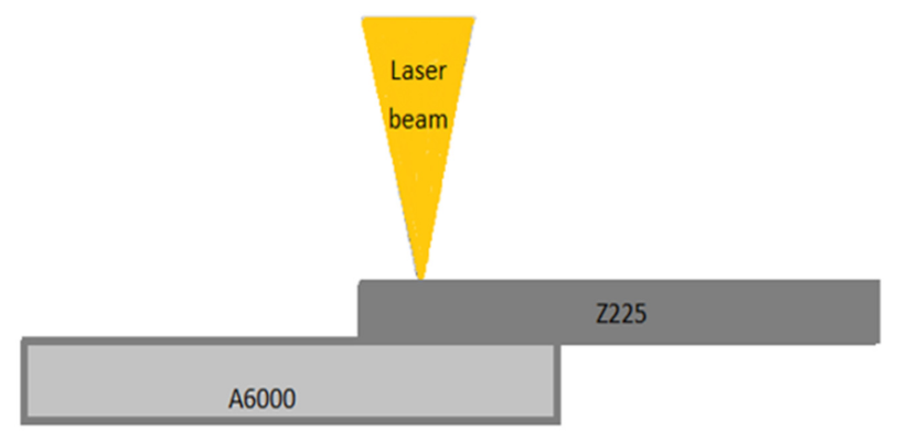
2.1. Materials and Laser Welding Method
2.2. Microstructure
2.3. Mechanical Properties
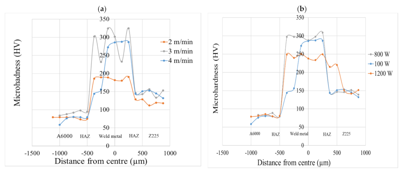
2.3.1. Microhardness Testing
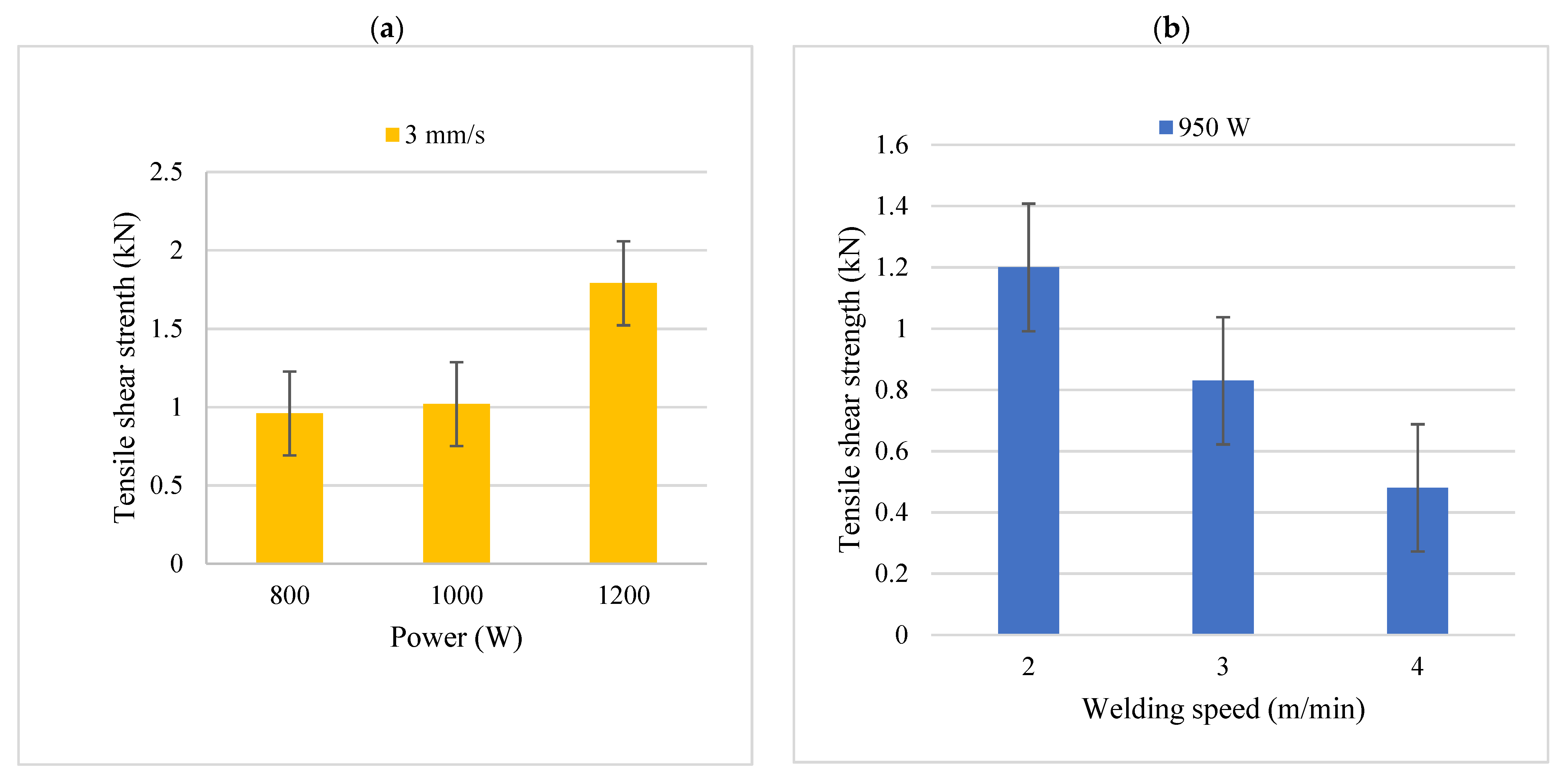
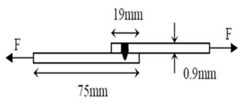
2.3.2. Tensile Strength Testing
2.4. Experimental Principle
2.5. System Parameters
3. Results and Discussion
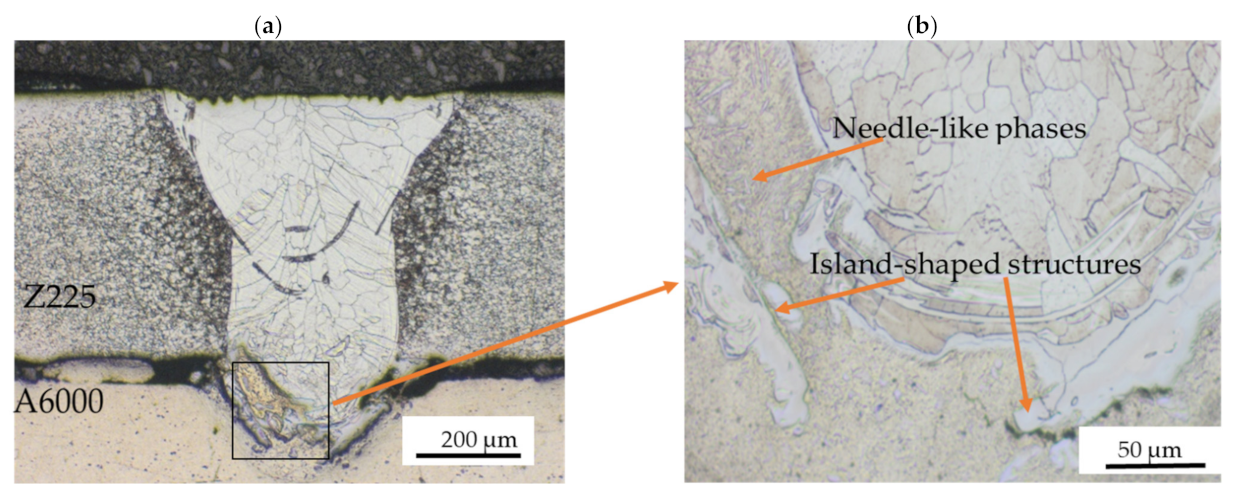
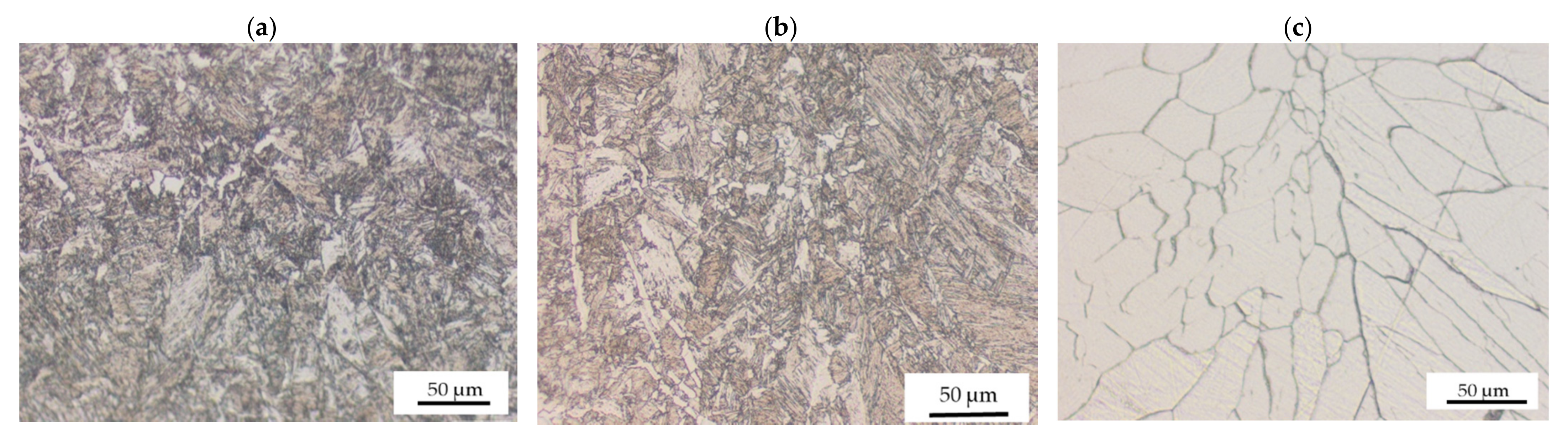
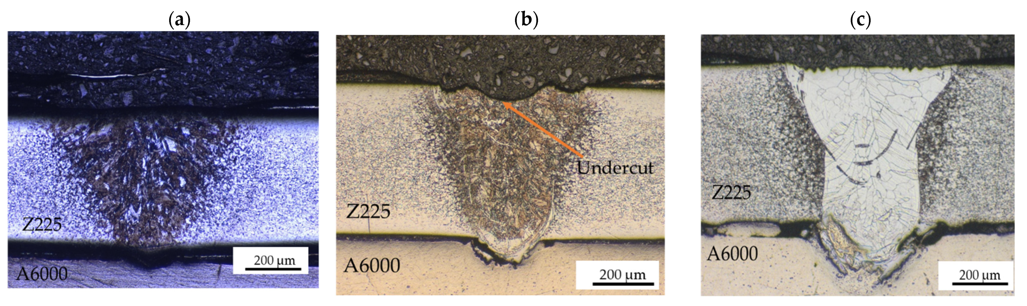
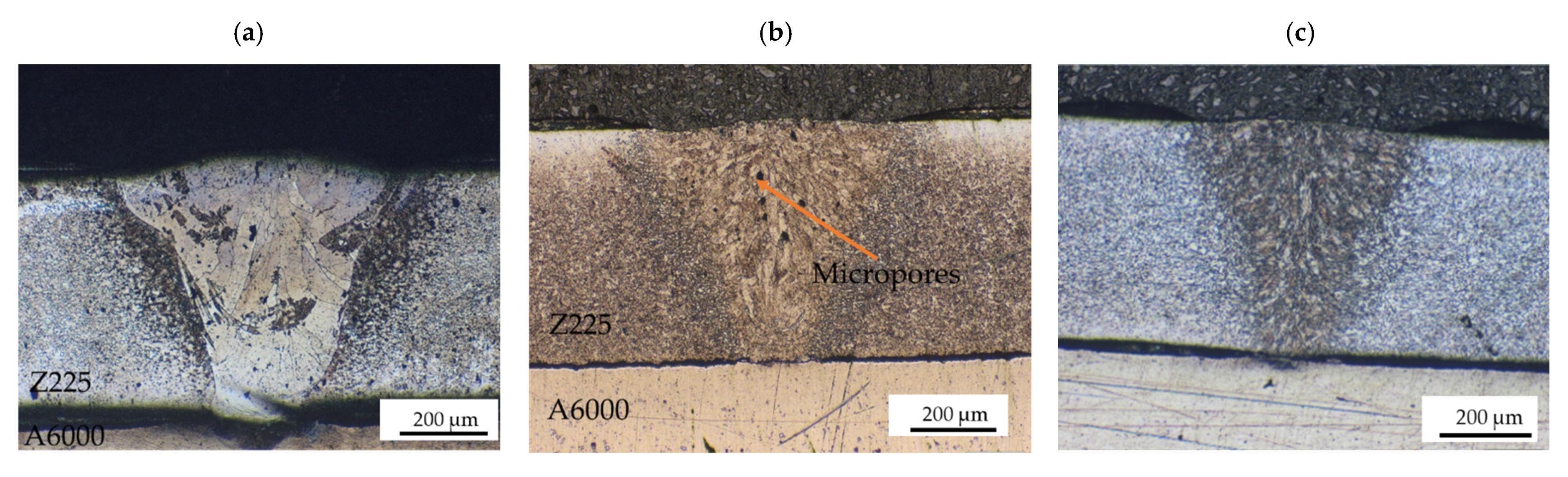
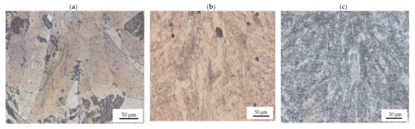
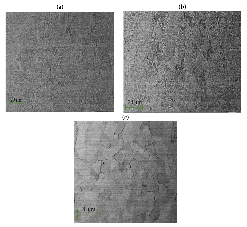
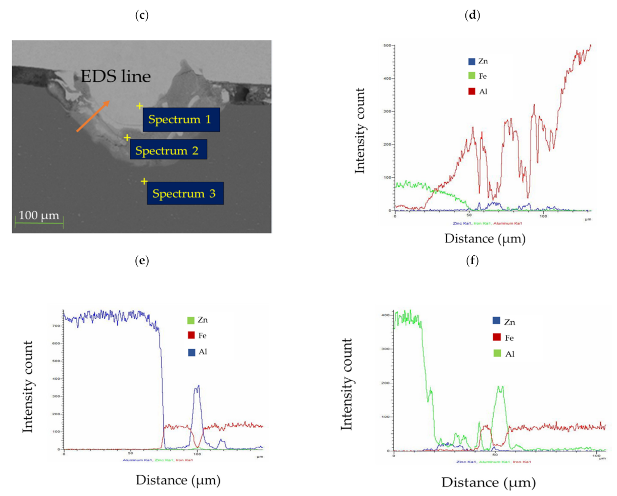
3.1. Microstructure
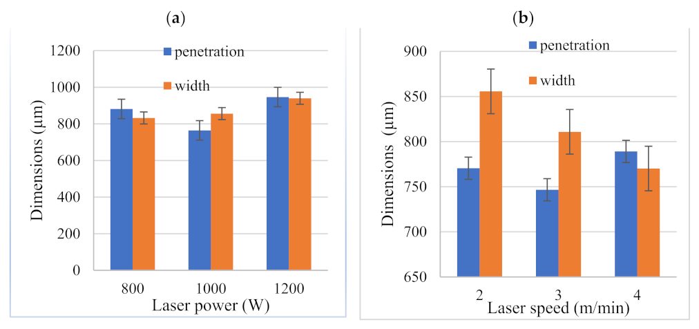
3.2. Mechanical Properties
4. Conclusions
Author Contributions
Funding
Institutional Review Board Statement
Informed Consent Statement
Data Availability Statement
Acknowledgments
Conflicts of Interest
References
- Berger, L.; Lesemann, M.; Sahr, C.; Hart, S.; Taylor, R. SuperLIGHT-CAR—The multi-material car body. In Proceedings of the 7th European LS-DYNA Conference, Salzburg, Austria, 14–15 May 2009; pp. 1–10. [Google Scholar]
- Fontaras, G.; Zacharof, N.G.; Ciuffo, B. Fuel consumption and CO2emissions from passenger cars in EuropeLaboratory versus real-world emissions, Prog. Energy Combust. Prog. Energy Combust. Sci. 2017, 60, 97–131. [Google Scholar] [CrossRef]
- Smallman, R.E.; Bishop, R.J. Modern Physical Metallurgy and Materials Engineering, 6th ed.; Butterworth-Heinemann: New Dehli, India, 1999. [Google Scholar]
- Guan, Q. Effect of steel to aluminium laser welding parameters on mechanical properties of weld beads. Opt. Opt. Laser Technol. 2019, 111, 387–394. [Google Scholar] [CrossRef]
- Chen, H.-C. Fibre Laser Welding of Dissimilar Materials. Ph.D. Thesis, Faculty of Engineering and Physical Sciences, The University of Manchester, Manchester, UK, 2010. [Google Scholar]
- Gao, M.; Chen, C.; Mei, S.W.; Wang, L.; Zeng, X.Y. Parameter optimization and mechanism of laser–arc hybrid welding of dissimilar Al alloy and stainless steel. Int. J. Adv. Manuf. Technol. 2014, 74, 199–208. [Google Scholar] [CrossRef]
- Sierra, G.; Peyre, P.; Beaume, F.D.; Stuart, D.; Fras, G. Steel to aluminium braze welding by laser process with Al–12Si filler wire. Sci. Technol. Weld. Join. 2008, 13, 430–437. [Google Scholar] [CrossRef]
- Tilekar, A.; Kamble, N.K. Optimization of laser welding parameters. Int. Res. J. Eng. Technol. 2017, 4, 1631–1633. [Google Scholar]
- Torkamany, M.J.; Tahamtan, S.; Sabbaghzadeh, J. Dissimilar welding of carbon steel to 5754 aluminum alloy by Nd: YAG pulsed laser. Mater. Des. 2010, 31, 458–465. [Google Scholar] [CrossRef]
- Yilbas, B.S.N.; Arif, A.F.M.; Aleem, B.J.A. Laser welding of mild steel sheets under nitrogen assisting gas ambient. Opt. Laser Technol. 2010, 42, 760–768. [Google Scholar] [CrossRef]
- Cheolhee, K.; Woongyong, C.; Jeonghan, K.; Sehun, R. The relationship between the weldability and the process parameters for Laser-TIG hybrid welding of galvanized steel sheets. Mater. Trans. 2008, 49, 179–186. [Google Scholar]
- Zhang, Y.; Hu, W.; Lai, X. Optimization of laser welding thin-gage galvanized steel via response surface methodology. Opt. Lasers Eng. 2012, 50, 1267–1273. [Google Scholar]
- Dasgupta, A.K.; Mazumder, J. Laser welding of zinc coated steel: An alternative to resistance spot welding. Sci. Technol. Weld. Join. 2008, 13, 289–293. [Google Scholar] [CrossRef]
- Kouadri-David, A.; P.S.M. (Process and Mechanical System) Team. Study of metallurgic and mechanical properties of laser welded heterogeneous joints between DP600 galvanised steel and aluminium 6082. Mater. Des. 2014, 54, 184–195. [Google Scholar] [CrossRef]
- Ozaki, H.; Kutsuna, M.; Nakagawa, S.; Miyamoto, K. Laser roll welding of dissimilar metal joint of zinc coated steel and aluminum alloy. J. Laser Appl. 2010, 22, 1–6. [Google Scholar] [CrossRef]
- Theron, M.; van Rooyen, C.; Ivanchev, L.H. CW Nd:YAG laser welding of dissimilar sheet metals. In Proceedings of the 26th International Congress on Applications of Lasers & Electro-Optics, Orlando, FL, USA, 29 October–1 November 2007; pp. 391–398. [Google Scholar]
- Michalis, N.; Christophe, A. High power fiber lasers: A review. IEEE J. Sel. Top. Quantum Electron. 2014, 20, 1–23. [Google Scholar]
- Cui, L. Dual beam laser keyhole welding of steel/aluminium lapped joints. J. Mater. Process. Technol. 2018, 256, 87–97. [Google Scholar] [CrossRef]
- Yuce, C.; Karpat, F.; Yavuz, N. Investigations on the microstructure and mechanical properties of laser welded dissimilar galvanized steel–aluminium joints. Int. J. Adv. Manuf. Technol. 2019, 104, 2693–2704. [Google Scholar] [CrossRef]
- O’Brien, A.; Guzman, C. Welding Handbook, 9th ed.; American Welding Society: Miami, MA, USA, 2007. [Google Scholar]
- Chen, W. Laser Welding of Thin Sheets of Galvanized Steel and Aluminum Alloy. Master’s Thesis, Iowa State University, Ames, IA, USA, 2006. [Google Scholar]
- Fabbro, R. Melt pool and keyhole behaviour analysis for deep penetration laser welding. J. Phys. D Appl. Phys. 2012, 43, 445–501. [Google Scholar] [CrossRef]
- Sierra, G.; Peyreb, P.; Deschaux-Beaume, F.; Stuart, D.; Fras, G. Steel to aluminium key-hole laser welding. Mater. Sci. Eng. 2006, 447, 197–208. [Google Scholar] [CrossRef]
- Phanikumar, G.; Chattopadhyay, K.; Dutta, P. Modelling of transport phenomena in laser welding of dissimilar metals. Int. J. Numer. Methods Heat Fluid Flow 2001, 11, 156–171. [Google Scholar] [CrossRef] [Green Version]
- Ovat, F.A. The Effect of Electrodes on the Mechanical Properties of Welded Steels, department of Mechanical Engineering. Master’s Thesis, University of Agriculture Makurdi, Makurdi, Nigeria, 2004. [Google Scholar]
- Meng, W. The influence of various factors on the geometric profile of laser lap welded T-joints. J. Laser Appl. 2015, 74, 1625–1636. [Google Scholar] [CrossRef]
- Martensite: Definition, Transformation & Microstructure. Available online: https://study.com/academy/lesson/martensite-definition-transformation-microstructure.html (accessed on 17 November 2021).
- Karim, A.; Park, Y. A Review on welding of dissimilar metals in car body manufacturing. J. Weld. Join. 2020, 38, 369–384. [Google Scholar]
- Radek, N.; Pietraszek, J.; Goroshko, A. The impact of laser welding parameters on the mechanical properties of the weld. In Proceedings of the 13th International Conference Electromachining, Bydgoszcz, Poland, 9–11 May 2018; pp. 1–7. [Google Scholar]
- Talabi, S.I. Effect of welding variable on mechanical properties of low carbon steel joint. Adv. Eng. Manuf. 2014, 9, 181–186. [Google Scholar] [CrossRef] [Green Version]
- Oyyaravelu, R.; Kuppan, P.; Arivazhagan, N. Metallurgical and mechanical properties of laserwelded high strength low alloy steel. J. Adv. Res. 2016, 7, 463–472. [Google Scholar] [CrossRef] [PubMed] [Green Version]
- Xu, W.; Li, Z.; Sun, X. Effect of welding speed on mechanical properties and the strain-hardening behavior of friction stir welded 7075 aluminum alloy joints. J. Mater. Eng. Perform. 2017, 26, 1938–1946. [Google Scholar] [CrossRef]
- Sahin, S.; Michael, K.; Markus, K.; Michael, F.Z. Influence of process temperature on hardness of friction stir welded high strength aluminium alloys for aerospace applications. Procedia CIRP 2014, 24, 120–124. [Google Scholar]
- Narsimhacharya, D.; Duttaa, K.; Shariffb, S.M.; Padmanabhamb, G.; Basua, A. Mechanical and microstructural characterization of laser weld-brazed AA6082-galvanized steel joint. J. Mater. Process. Technol. 2019, 263, 21–32. [Google Scholar] [CrossRef]
- Zhengwei, G.U. Influence of welding speed on microstructure and properties of ultra-high strength steel sheets in laser welding. ISIJ Int. 2018, 52, 483–487. [Google Scholar]


| Elements (wt.%) | |||
|---|---|---|---|
| Si | Mg | Cu | |
| A6000 | 1.0 | 0.5 | <0.1 |
| Material | C | Si | P |
| Z225 | <0.15 | <0.60 | <0.05 |
| Parent Metal | Yield Strength (MPa) | Ultimate Tensile Strength (MPa) | Elongation (%) |
|---|---|---|---|
| A6000 | 225 | 303 | 15 |
| Z225 | 350 | 375 | 35 |
| System Parameters | ||
|---|---|---|
| Power (W) | Welding Speed (m/min) | Heat Input (105 J/mm) |
| 800 | 3 | 16 |
| 950 | 2 | 28.5 |
| 950 | 3 | 19 |
| 950 | 4 | 14.25 |
| 1000 | 3 | 20 |
| 1200 | 3 | 24 |
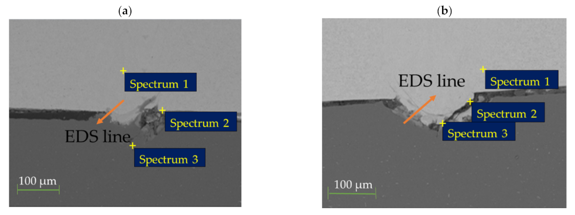
| Power | 800 W | 1000 W | 1200 W | ||||||
|---|---|---|---|---|---|---|---|---|---|
| Weight (%) | Fe | Al | Phase | Fe | Al | Phase | Fe | Al | Phase |
| Spectrum 1 | 100.0 | 0 | Fe-rich | 100 | 0 | Fe-rich | 77.60 | 22.40 | Fe-rich |
| Spectrum 2 | 94.05 | 5.95 | Fe-rich | 24.04 | 75.96 | FeAl3 | 34.13 | 65.87 | Fe2Al5 |
| Spectrum 3 | 0.24 | 99.76 | Al-rich | 1.08 | 98.92 | Al-rich | 20.21 | 79.79 | Al-rich |
Publisher’s Note: MDPI stays neutral with regard to jurisdictional claims in published maps and institutional affiliations. |
© 2022 by the authors. Licensee MDPI, Basel, Switzerland. This article is an open access article distributed under the terms and conditions of the Creative Commons Attribution (CC BY) license (https://creativecommons.org/licenses/by/4.0/).
Share and Cite
Ramaphoko, N.A.; Skhosane, S.; Maledi, N. Microstructural Characterization and Mechanical Properties of Laser Beam-Welded Dissimilar Joints between A6000 Aluminum Alloy and Galvanized Steel. Materials 2022, 15, 543. https://doi.org/10.3390/ma15020543
Ramaphoko NA, Skhosane S, Maledi N. Microstructural Characterization and Mechanical Properties of Laser Beam-Welded Dissimilar Joints between A6000 Aluminum Alloy and Galvanized Steel. Materials. 2022; 15(2):543. https://doi.org/10.3390/ma15020543
Chicago/Turabian StyleRamaphoko, Nkopane Angelina, Samuel Skhosane, and Nthabiseng Maledi. 2022. "Microstructural Characterization and Mechanical Properties of Laser Beam-Welded Dissimilar Joints between A6000 Aluminum Alloy and Galvanized Steel" Materials 15, no. 2: 543. https://doi.org/10.3390/ma15020543
APA StyleRamaphoko, N. A., Skhosane, S., & Maledi, N. (2022). Microstructural Characterization and Mechanical Properties of Laser Beam-Welded Dissimilar Joints between A6000 Aluminum Alloy and Galvanized Steel. Materials, 15(2), 543. https://doi.org/10.3390/ma15020543