
In Situ Investigation of Microstructural Evolution and Intermetallic Compounds Formation at Liquid Al/Solid Cu Interface by Synchrotron X-ray Radiography

Abstract
:1. Introduction
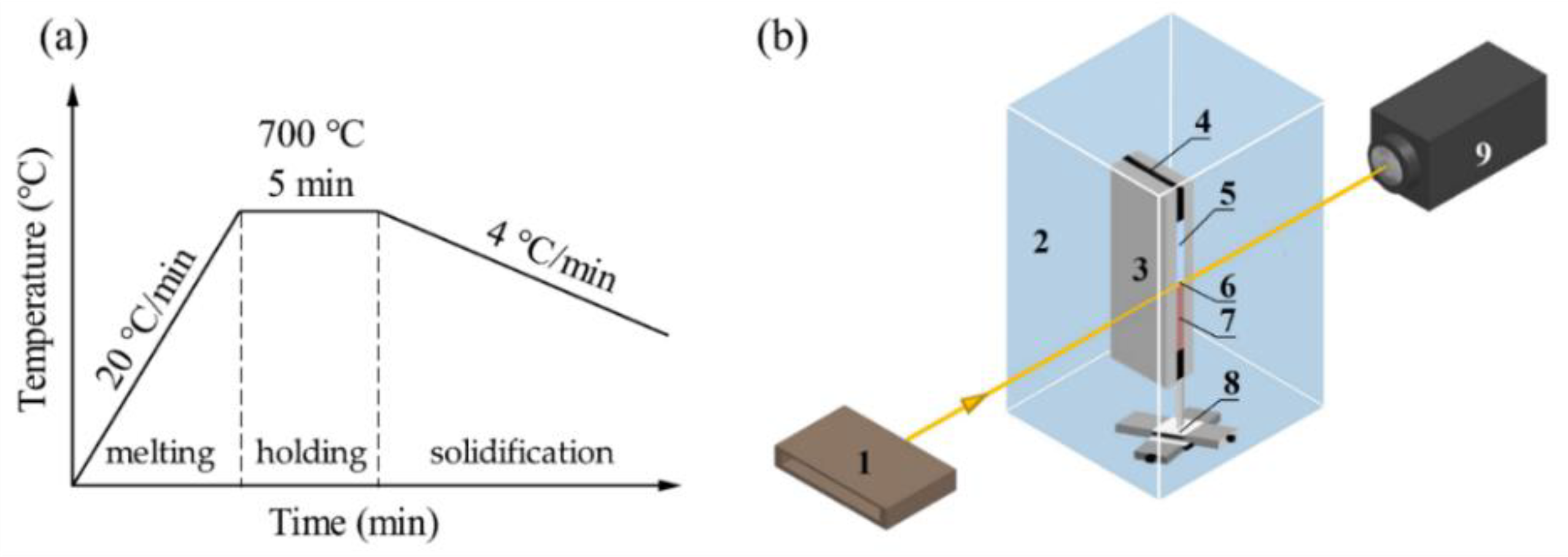
2. Materials and Methods
3. Results and Discussion
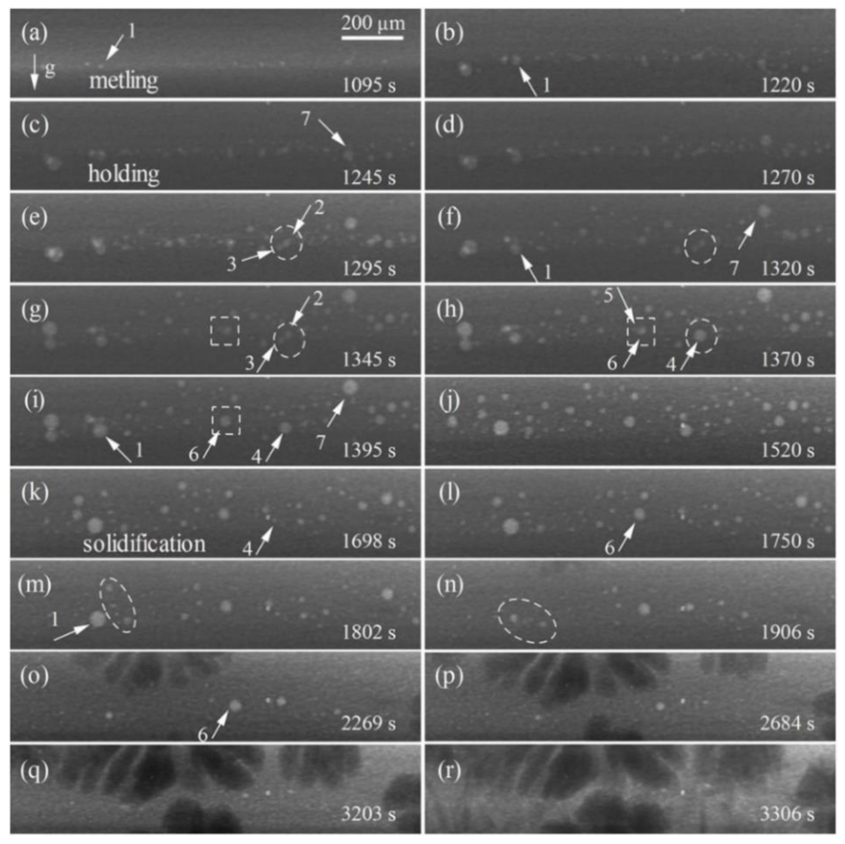
3.1. Dynamic Evolution of Diffusion and Solidification
3.2. Formation and Evolution of Bubbles
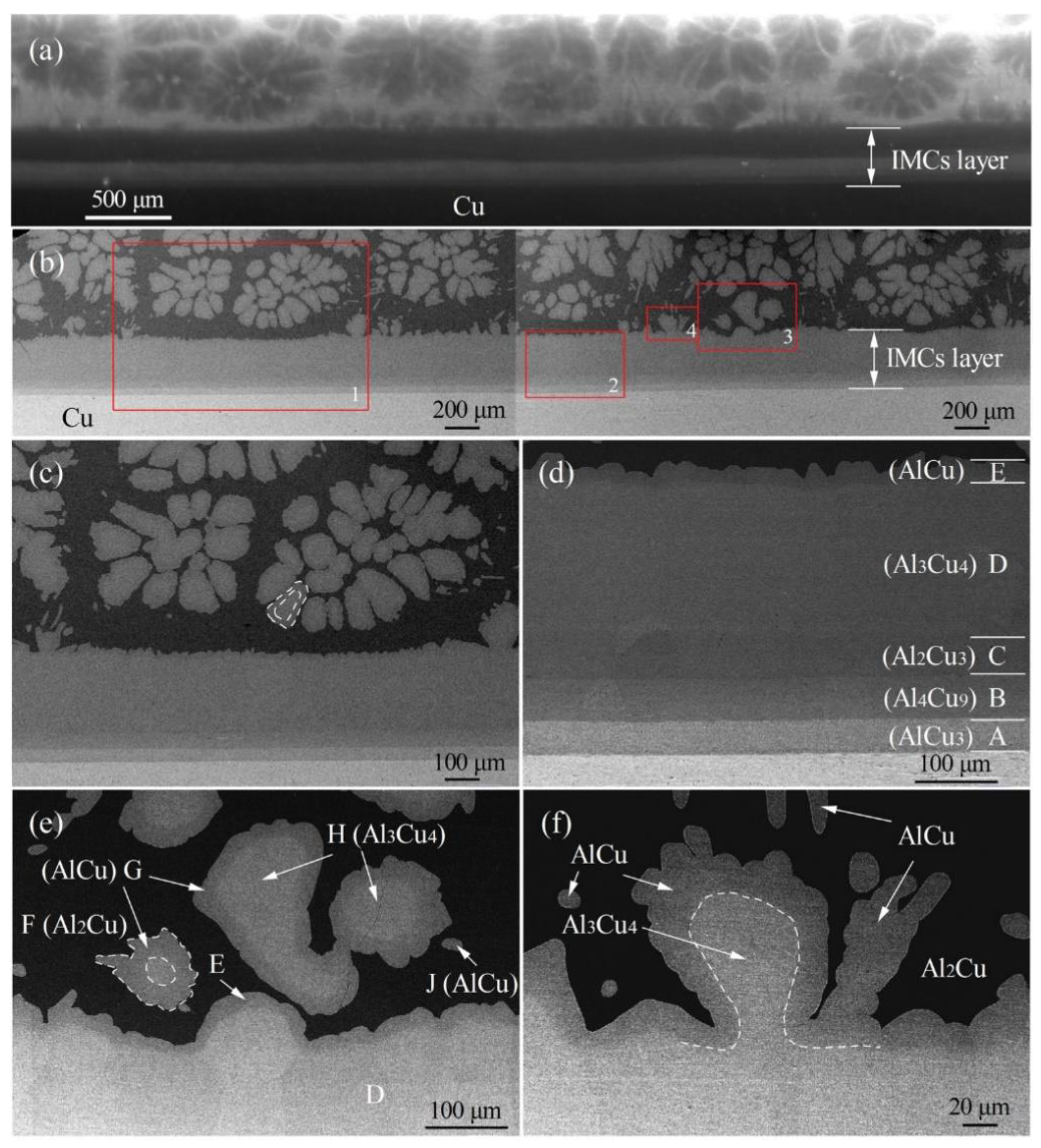
3.3. Determination and Evolution of Interfacial Microstructure
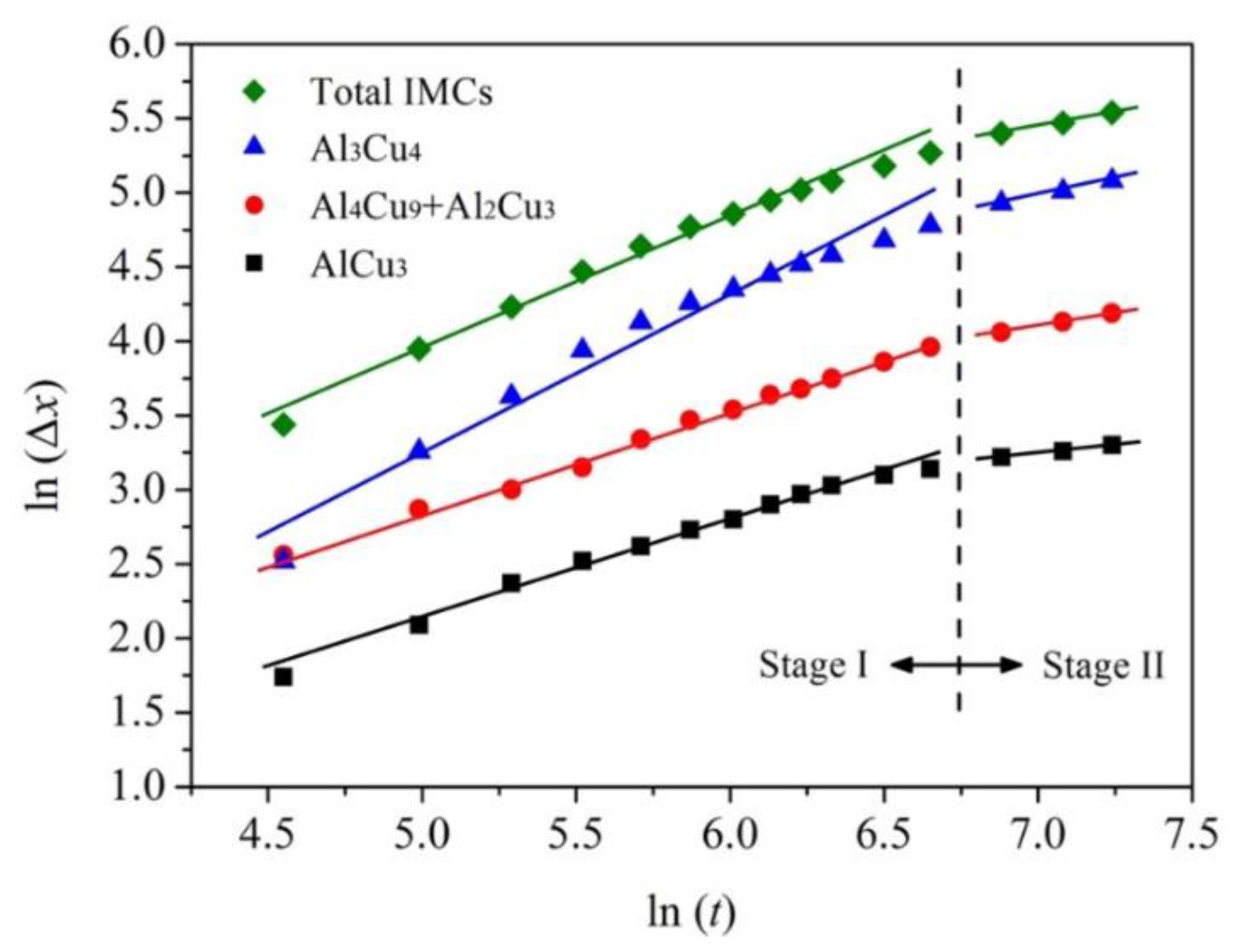
3.4. Growth Kinetics of IMCs
4. Conclusions
Author Contributions
Funding
Institutional Review Board Statement
Informed Consent Statement
Data Availability Statement
Acknowledgments
Conflicts of Interest
References
- Hu, Y.; Chen, Y.Q.; Li, L.; Hu, H.D.; Zhu, Z.A. Microstructure and properties of Al/Cu bimetal in liquid-solid compound casting process. Trans. Nonferrous Met. Soc. China 2016, 26, 1555–1563. [Google Scholar] [CrossRef]
- Han, Y.Q.; Ben, L.H.; Yao, J.J.; Wu, C.J. Microstructural characterization of Cu/Al composites and effect of cooling rate at the Cu/Al interfacial region. Int. J. Miner. Metall. Mater. 2015, 22, 94–101. [Google Scholar] [CrossRef]
- Mao, Z.P.; Xie, J.P.; Wang, A.Q.; Wang, W.Y.; Ma, D.Q.; Liu, P. Effects of annealing temperature on the interfacial microstructure and bonding strength of Cu/Al clad sheets produced by twin-roll casting and rolling. J. Mater. Process. Tech. 2020, 285, 116804. [Google Scholar] [CrossRef]
- Sasaki, T.T.; Morris, R.A.; Thompson, G.B.; Syarif, Y.; Fox, D. Formation of ultra-fine copper grains in copper-clad aluminum wire. Scr. Mater. 2010, 63, 488–491. [Google Scholar] [CrossRef]
- Zou, J.T.; Gao, L.; Xie, T.F.; Li, S.L.; Sun, L.X.; Liang, S.H. Interfacial microstructure and shear strength of Cu/Al bimetal fabricated by diffusion welding. Rare Met. Mater. Eng. 2020, 49, 4121–4128. [Google Scholar]
- Fu, X.; Wang, R.; Zhu, Q.F.; Wang, P.; Zuo, Y.B. Effect of annealing on the interface and mechanical properties of Cu-Al-Cu laminated composite prepared with cold rolling. Materials 2020, 13, 369. [Google Scholar] [CrossRef] [PubMed]
- Wang, X.G. Microstructure and Properties of Cu-Al Dissimilar Joint by Transient Liquid Phase Bonding. Ph.D. Thesis, Shandong University, Jinan, China, 2015. [Google Scholar]
- Wang, J.; Zhao, F.; Xie, G.L.; Hou, Y.F.; Wang, R.; Liu, X.H. Rolling deformation behaviour and interface evaluation of Cu-Al bimetallic composite plates fabricated by horizontal continuous composite casting. J. Mater. Process. Tech. 2021, 298, 117296. [Google Scholar] [CrossRef]
- Liu, G.P.; Wang, Q.D.; Zhang, L.; Ye, B.; Jiang, H.Y.; Ding, W.J. Effects of melt-to-solid volume ratio and pouring temperature on microstructures and mechanical properties of Cu/Al bimetals in compound casting process. Metall. Mater. Trans. A 2019, 50, 401–414. [Google Scholar] [CrossRef]
- Shayanpoor, A.A.; Rezaei Ashtiani, H.R. Microstructural and mechanical investigations of powder reinforced interface layer of hot extruded Al/Cu bimetallic composite rods. J. Manuf. Processes 2022, 77, 313–328. [Google Scholar] [CrossRef]
- Zhang, H.A.; Chen, G. Fabrication of Cu/Al compound materials by solid-liquid bonding method and interface bonding mechanism. China J. Nonferrous Met. 2008, 18, 414–420. [Google Scholar]
- Su, Y.J.; Liu, X.H.; Huang, H.Y.; Liu, X.F.; Xie, J.X. Interfacial microstructure and bonding strength of copper cladding aluminum rods fabricated by horizontal core-filling continuous casting. Metall. Mater. Trans. A 2011, 42, 4088–4099. [Google Scholar] [CrossRef]
- Tavassoli, S.; Abbasi, M.; Tahavvori, R. Controlling of IMCs layers formation sequence, bond strength and electrical resistance in Al/Cu bimetal compound casting process. Mater. Des. 2016, 108, 343–353. [Google Scholar] [CrossRef]
- Bakke, A.O.; Arnberg, L.; Li, Y.J. Achieving high-strength metallurgical bonding between A356 aluminum and copper through compound casting. Mater. Sci. Eng. A 2021, 810, 140979. [Google Scholar] [CrossRef]
- Wang, Y.B.; Jia, S.S.; Wei, M.G.; Peng, L.M.; Wu, Y.J.; Liu, X.T. Research progress on solidification structure of alloys by synchrotron X-ray radiography: A review. J. Magnes. Alloys 2020, 8, 396–413. [Google Scholar] [CrossRef]
- Wang, T.M.; Cao, F.; Zhou, P.; Kang, H.J.; Chen, Z.N.; Fu, Y.N.; Xiao, T.Q.; Huang, W.X.; Yuan, Q.X. Study on diffusion behavior and microstructural evolution of Al/Cu bimetal interface by synchrotron X-ray radiography. J. Alloys Compd. 2014, 616, 550–555. [Google Scholar] [CrossRef]
- Ding, Z.Y.; Hu, Q.D.; Lu, W.Q.; Xu, X.W.; Ge, X.; Cao, S.; Yang, T.X.; Ge, H.H.; Xia, M.X.; Li, J.G. A full view of the interfacial behavior between the liquid Al and solid Ni by synchrotron radiation. Metall. Mater. Trans. A 2019, 50, 300–310. [Google Scholar] [CrossRef]
- Bogno, A.; Nguyen-Thi, A.H.; Bergeon, N.; Mangelinck-Noël, N.; Schenk, T.; Billia, B.; Boller, E.; Baruchel, J. Application of synchrotron X-ray radiography to the study of dendritic equiaxed microstructure formation in Al-Cu alloys. Nucl. Instrum. Methods Phys. Res. Sect. B 2010, 268, 394–398. [Google Scholar] [CrossRef]
- Wei, P.S.; Hsiao, S.Y. Pore formation from bubble entrapment by a solidification front. Am. J. Heat Mass Trans. 2015, 2, 76–88. [Google Scholar] [CrossRef]
- Ding, Z.Y.; Hu, Q.D.; Lu, W.Q.; Ge, X.; Cao, S.; Sun, S.Y.; Yang, T.X.; Xia, M.X.; Li, J.G. In-situ study on hydrogen bubble evolution in the liquid Al/solid Ni interconnection by synchrotron radiation X-ray radiography. J. Mater. Sci. Technol. 2019, 35, 1388–1392. [Google Scholar] [CrossRef]
- Tiwari, S.N.; Beech, J. Origin of gas bubbles in aluminium. Met. Sci. 1978, 12, 356–362. [Google Scholar] [CrossRef]
- Kato, E. Pore nucleation in solidifying high-purity copper. Metall. Mater. Trans. A 1999, 30, 2449–2453. [Google Scholar] [CrossRef]
- Liu, L.; Samuel, A.M.; Samuel, F.H.; Doty, H.W.; Valtierra, S. Influence of oxides on porosity formation in Sr-treated Al-Si casting alloys. J. Mater. Sci. 2003, 38, 1255–1267. [Google Scholar] [CrossRef]
- Jia, J.; Zhao, J.Z.; Guo, J.J.; Liu, Y. Immiscible Alloy and Its Preparation Technology; Harbin Institute of Technology Press: Harbin, China, 2004; pp. 70–84. [Google Scholar]
- Kerr, H.W.; Kurz, W. Solidification of peritectic alloys. Int. Mater. Rev. 1996, 41, 129–164. [Google Scholar] [CrossRef]
- Shen, J.; Chan, Y.C.; Liu, S.Y. Growth mechanism of Ni3Sn4 in a Sn/Ni liquid/solid interfacial reaction. Acta Mater. 2009, 57, 5196–5206. [Google Scholar] [CrossRef]
- Shen, J.; Zhao, M.; He, P.; Pu, Y. Growth behaviors of intermetallic compounds at Sn-3Ag-0.5Cu/Cu interface during isothermal and non-isothermal aging. J. Alloys Compd. 2013, 574, 451–458. [Google Scholar] [CrossRef]
- Wang, Y.; Vecchio, K.S. Microstructure evolution in a martensitic 430 stainless steel-Al metallic-intermetallic laminate (MIL) composite. Mater. Sci. Eng. A 2015, 643, 72–85. [Google Scholar] [CrossRef]


| SEM (Figure 5) | Phases | In-Situ Radiograph (Figure 2) | Morphology | Al-Cu Phase Diagram |
|---|---|---|---|---|
| A | AlCu3 | Phase I1 | Layered | 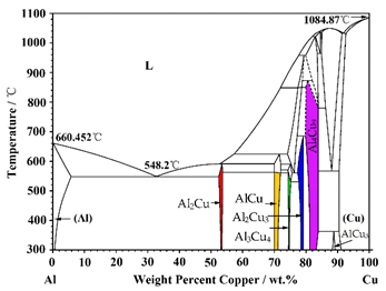 |
| B | Al4Cu9 | Phase I2 | Layered | |
| C | Al2Cu3 | Phase I2 | Layered | |
| D | Al3Cu4 | Phase I3 | Layered | |
| H | Al3Cu4 | Phase II | Petal-shaped | |
| E, G | AlCu | Phase III1 | Cladding layer | |
| J | AlCu | Phase III2 | Needle-like | |
| F | Al2Cu | Phase IV | — |
| Layer | AlCu3 | Al4Cu9 + Al2Cu3 | Al3Cu4 | Total IMCs |
|---|---|---|---|---|
| Stage I | 0.67 | 0.68 | 1.03 | 0.86 |
| Stage II | 0.22 | 0.36 | 0.42 | 0.39 |
Publisher’s Note: MDPI stays neutral with regard to jurisdictional claims in published maps and institutional affiliations. |
© 2022 by the authors. Licensee MDPI, Basel, Switzerland. This article is an open access article distributed under the terms and conditions of the Creative Commons Attribution (CC BY) license (https://creativecommons.org/licenses/by/4.0/).
Share and Cite
Cao, F.; Wang, R.; Zhang, P.; Wang, T.; Song, K. In Situ Investigation of Microstructural Evolution and Intermetallic Compounds Formation at Liquid Al/Solid Cu Interface by Synchrotron X-ray Radiography. Materials 2022, 15, 5647. https://doi.org/10.3390/ma15165647
Cao F, Wang R, Zhang P, Wang T, Song K. In Situ Investigation of Microstructural Evolution and Intermetallic Compounds Formation at Liquid Al/Solid Cu Interface by Synchrotron X-ray Radiography. Materials. 2022; 15(16):5647. https://doi.org/10.3390/ma15165647
Chicago/Turabian StyleCao, Fei, Ruosi Wang, Peng Zhang, Tongmin Wang, and Kexing Song. 2022. "In Situ Investigation of Microstructural Evolution and Intermetallic Compounds Formation at Liquid Al/Solid Cu Interface by Synchrotron X-ray Radiography" Materials 15, no. 16: 5647. https://doi.org/10.3390/ma15165647
APA StyleCao, F., Wang, R., Zhang, P., Wang, T., & Song, K. (2022). In Situ Investigation of Microstructural Evolution and Intermetallic Compounds Formation at Liquid Al/Solid Cu Interface by Synchrotron X-ray Radiography. Materials, 15(16), 5647. https://doi.org/10.3390/ma15165647