
AlSi10Mg in Powder Bed Fusion with Laser Beam: An Old and Boring Material?


Abstract
:1. Introduction
2. Materials and Methods
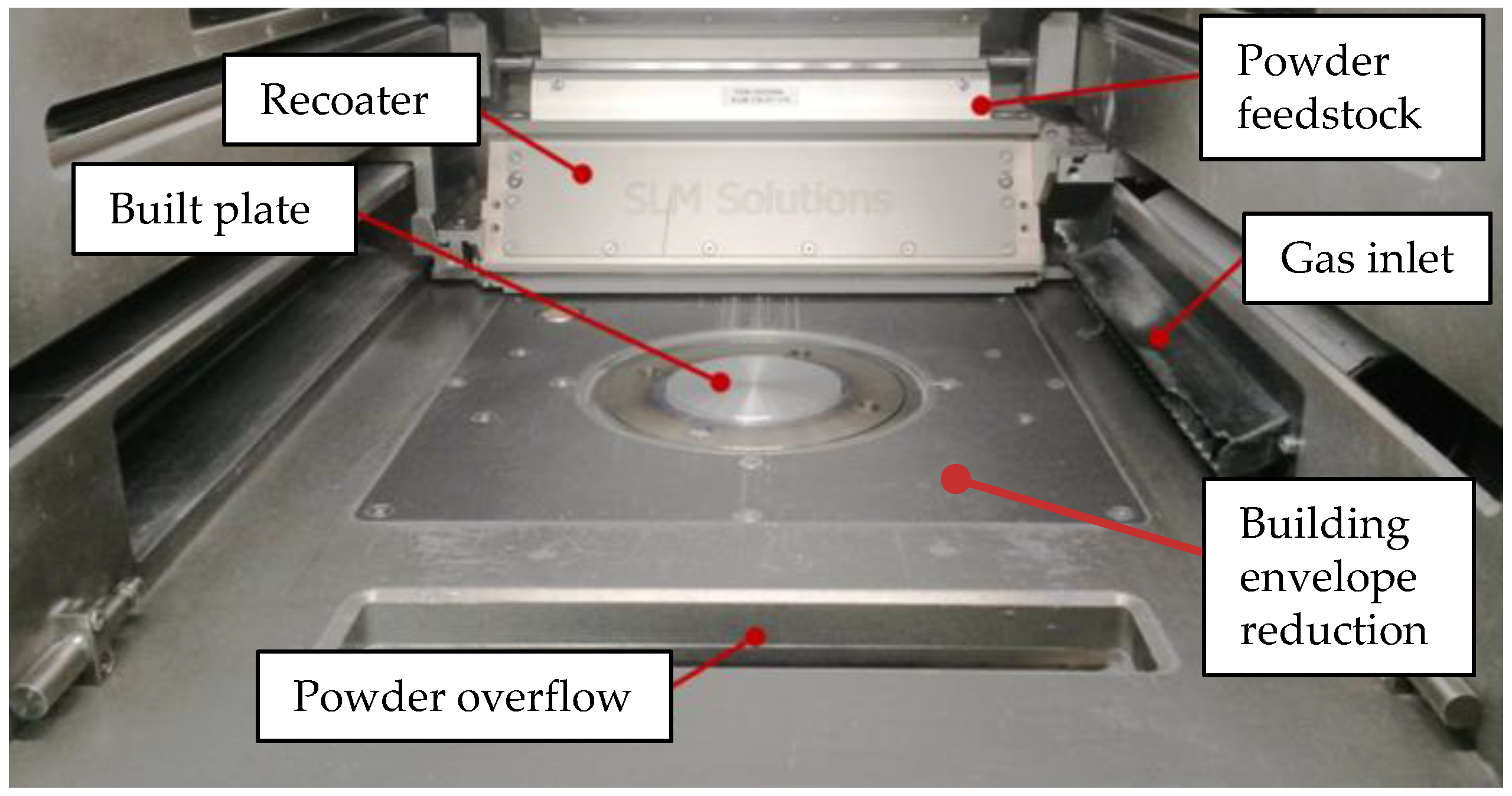
2.1. Machines and Materials
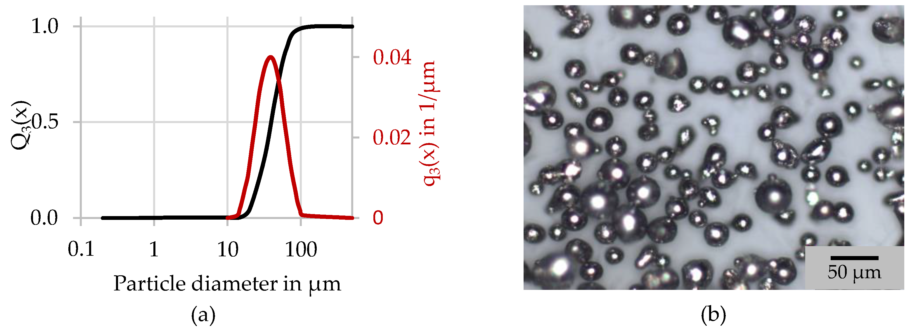
2.2. Used Material
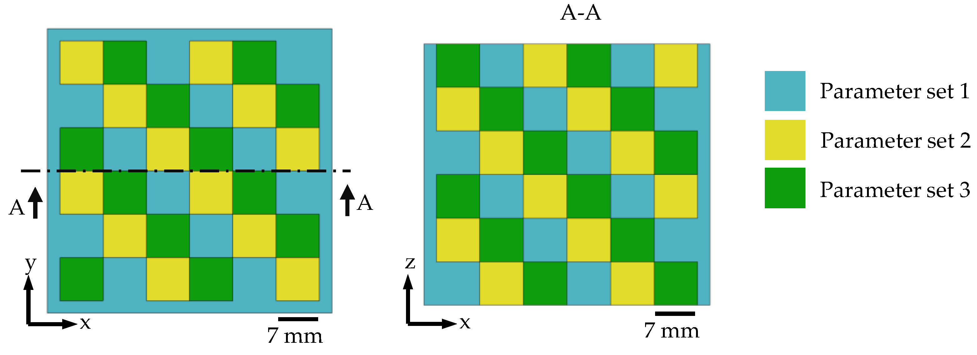
2.3. Used Process Parameters
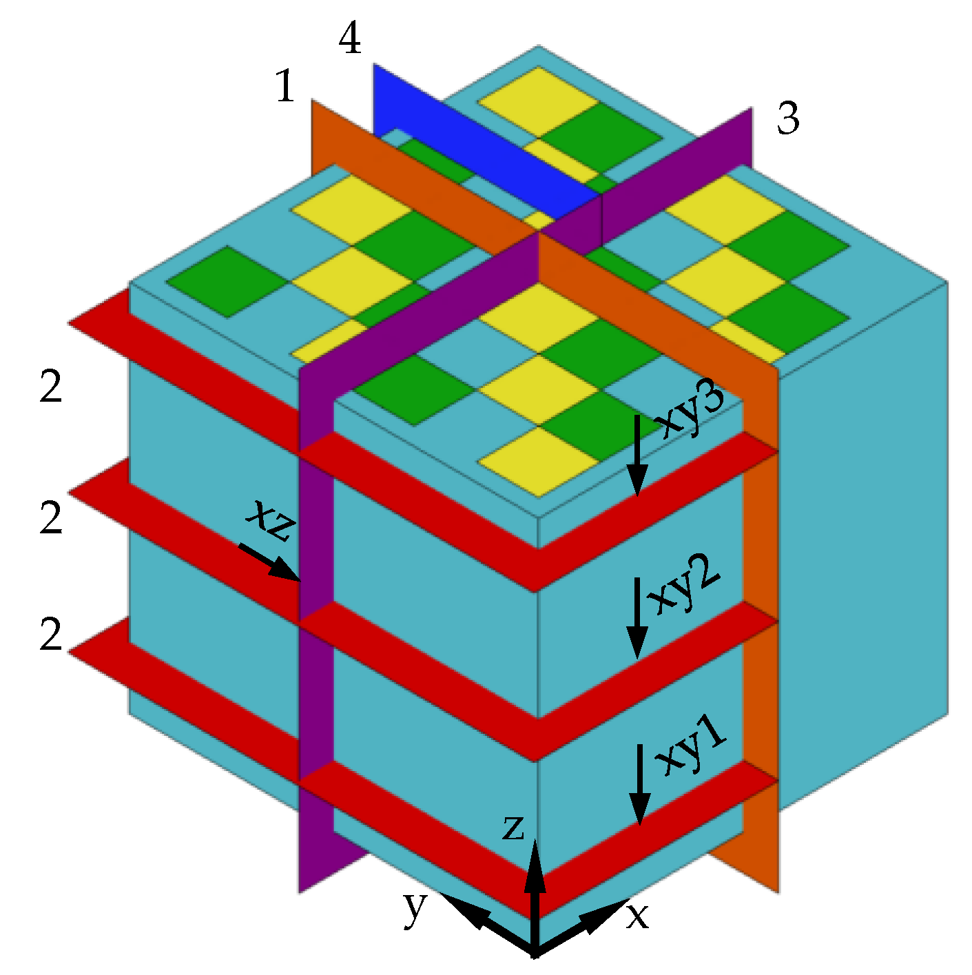
2.4. Characterization
3. Results and Discussion
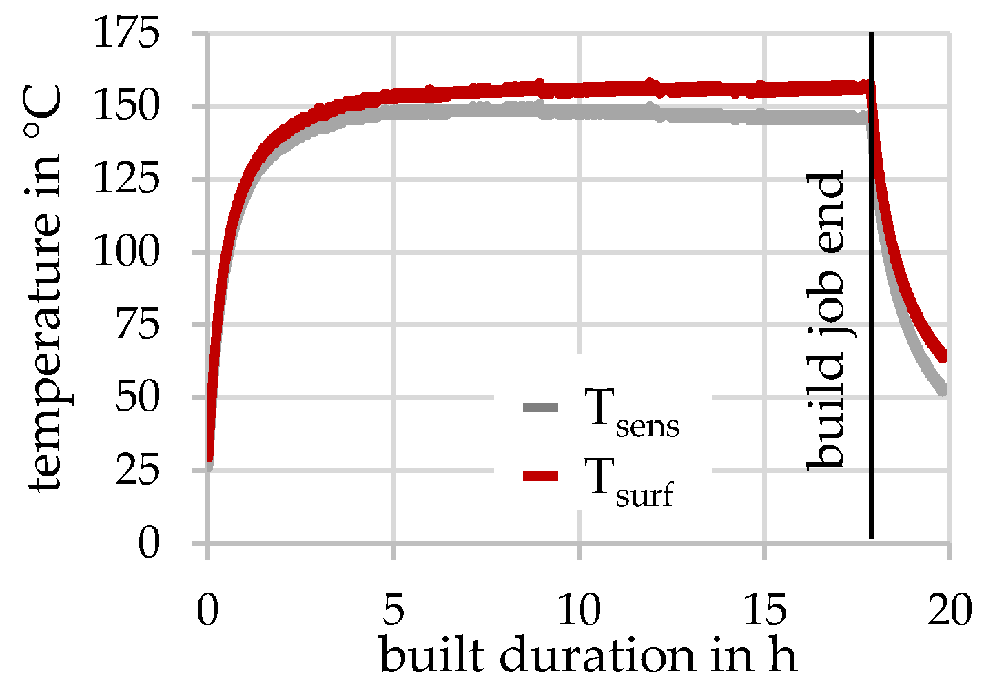
3.1. Evaluation of the Temperature Sensoric
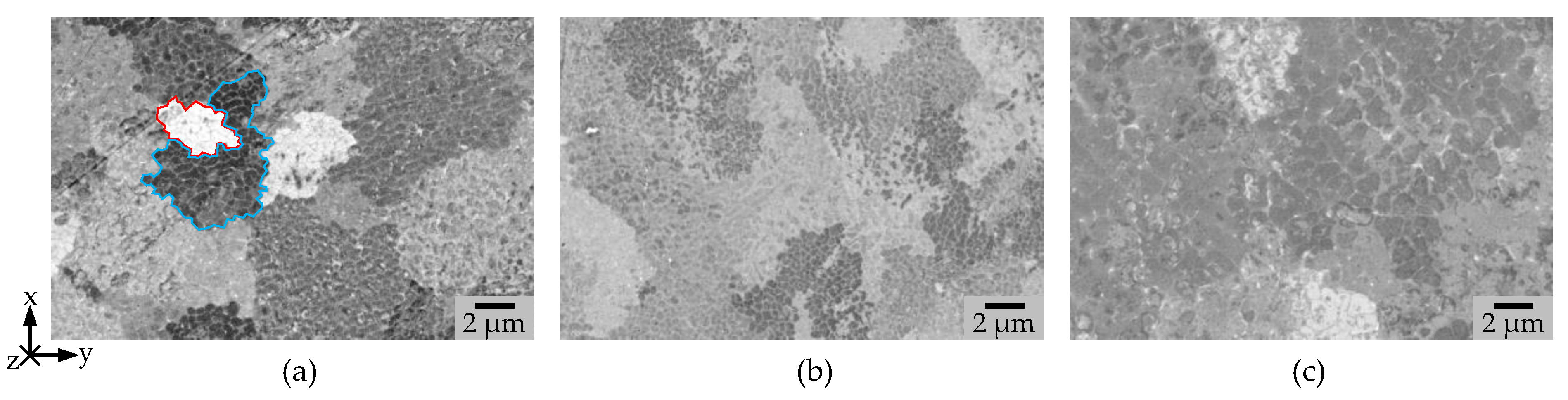
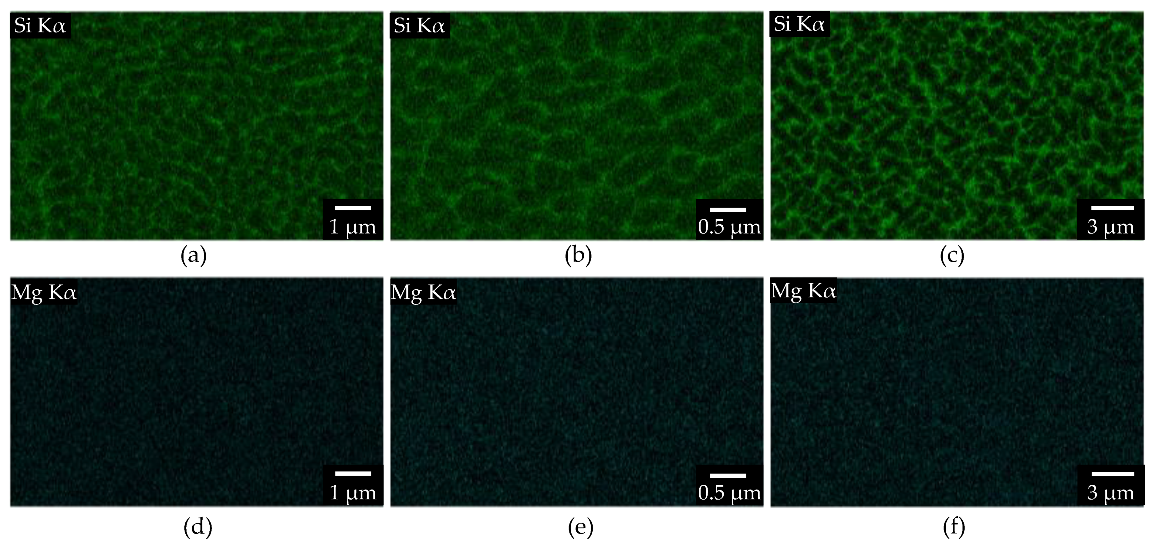
3.2. Microstructure
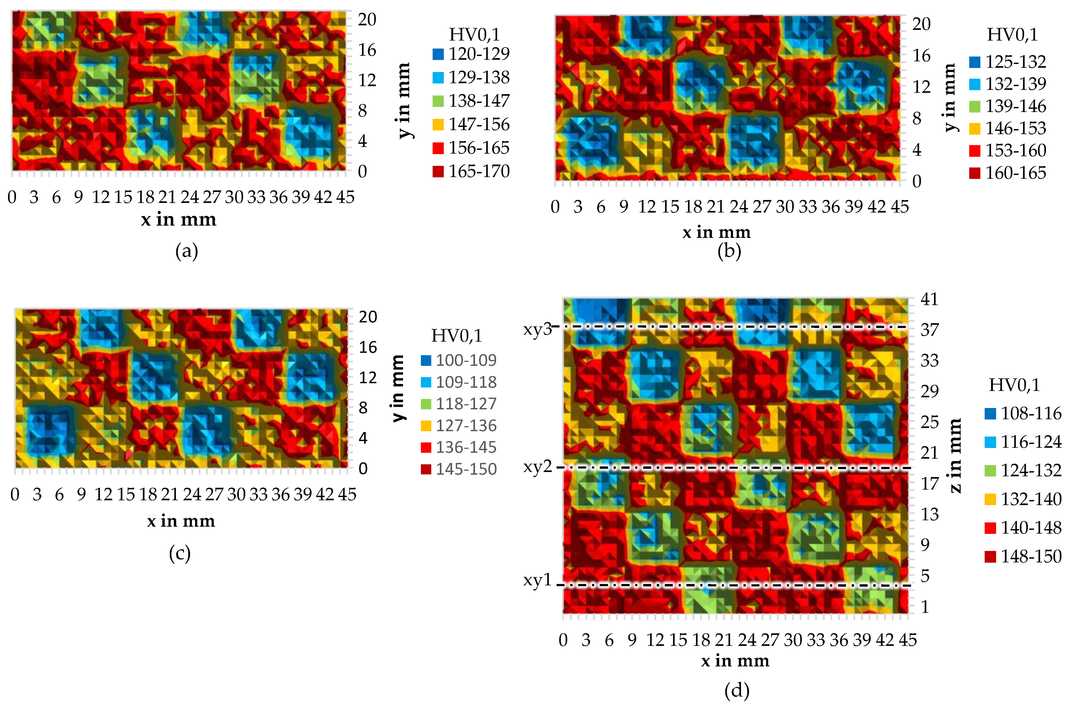
3.3. Microhardness
4. Conclusions and Outlook
Author Contributions
Funding
Institutional Review Board Statement
Informed Consent Statement
Acknowledgments
Conflicts of Interest
References
- Schmidt, M.; Merklein, M.; Bourell, D.; Dimitrov, D.; Hausotte, T.; Wegener, K.; Overmeyer, L.; Vollertsen, F.; Levy, G.N. Laser Based Additive Manufacturing in Industry and Academia. CIRP Ann. 2017, 66, 561–583. [Google Scholar] [CrossRef]
- Wohlers, T.; Campbell, R.I.; Diegel, O.; Kowen, J.; Ray Huff, N.M. Wohlers Report 2021; Wohlers Associates: Fort Collins, CO, USA, 2021; p. 375. [Google Scholar]
- Van der Schueren, B.; Kruth, J.-P. Laser Based Selective Metal Powder Sintering: A Feasibility Study. In Proceedings of the Laser Assisted Net Shape Engineering, Erlangen, Germany, 10–12 October 1994; pp. 517–523. [Google Scholar]
- Meiners, W. Direktes Selektives Laser Sintern Einkomponentiger Metallischer Werkstoffe; Shaker Verlag: Herzogenrath, Germany, 1999; ISBN 3826565711. [Google Scholar]
- Over, C. Generative Fertigung von Bauteilen Aus Werkzeugstahl X38CrMoV5-1 und Titan TiAl6V4 Mit “Selective Laser Melting”; Shaker Verlag: Herzogenrath, Germany, 2003; ISBN 3832222456. [Google Scholar]
- Zhang, D. Entwicklung des Selective Laser Melting (SLM) für Aluminium; Shaker Verlag: Herzogenrath, Germany, 2004; Volume 82, ISBN 3832231048. [Google Scholar]
- Buchbinder, D. Selective Laser Melting von Aluminiumgusslegierungen; Shaker Verlag: Herzogenrath, Germany, 2013; ISBN 9783844024395. [Google Scholar]
- Weingarten, C.; Buchbinder, D.; Pirch, N.; Meiners, W.; Wissenbach, K.; Poprawe, R. Formation and Reduction of Hydrogen Porosity during Selective Laser Melting of AlSi10Mg. J. Mater. Process. Technol. 2015, 221, 112–120. [Google Scholar] [CrossRef]
- Buchbinder, D.; Schleifenbaum, H.; Heidrich, S.; Meiners, W.; Bültmann, J. High Power Selective Laser Melting (HP SLM) of Aluminum Parts. Phys. Procedia 2011, 12, 271–278. [Google Scholar] [CrossRef]
- Siddique, S.; Imran, M.; Wycisk, E.; Emmelmann, C.; Walther, F. Influence of Process-Induced Microstructure and Imperfections on Mechanical Properties of AlSi12 Processed by Selective Laser Melting. J. Mater. Process. Technol. 2015, 221, 205–213. [Google Scholar] [CrossRef]
- Fiocchi, J.; Biffi, C.A.; Tuissi, A. Selective Laser Melting of High-Strength Primary AlSi9Cu3 Alloy: Processability, Microstructure, and Mechanical Properties. Mater. Des. 2020, 191, 108581. [Google Scholar] [CrossRef]
- Lam, L.P.; Zhang, D.Q.; Liu, Z.H.; Chua, C.K. Phase Analysis and Microstructure Characterisation of AlSi10Mg Parts Produced by Selective Laser Melting. Virtual Phys. Prototyp. 2015, 10, 207–215. [Google Scholar] [CrossRef]
- Fiocchi, J.; Tuissi, A.; Bassani, P.; Biffi, C.A. Low Temperature Annealing Dedicated to AlSi10Mg Selective Laser Melting Products. J. Alloys Compd. 2017, 695, 3402–3409. [Google Scholar] [CrossRef]
- Li, W.; Li, S.; Liu, J.; Zhang, A.; Zhou, Y.; Wei, Q.; Yan, C.; Shi, Y. Effect of Heat Treatment on AlSi10Mg Alloy Fabricated by Selective Laser Melting: Microstructure Evolution, Mechanical Properties and Fracture Mechanism. Mater. Sci. Eng. A 2016, 663, 116–125. [Google Scholar] [CrossRef]
- Aboulkhair, N.T.; Tuck, C.; Ashcroft, I.; Maskery, I.; Everitt, N.M. On the Precipitation Hardening of Selective Laser Melted AlSi10Mg. Metall. Mater. Trans. A Phys. Metall. Mater. Sci. 2015, 46, 3337–3341. [Google Scholar] [CrossRef]
- SLM Solutions GmbH. Analysis Certificate AlSi10Mg Powder; SLM Solutions GmbH: Lübeck, Germany, 2019. [Google Scholar]
- DIN EN 1706:2020-06; Aluminium Und Aluminiumlegierungen—Gussstücke—Chemische Zusammensetzung Und Mechanische Eigenschaften. Beuth Verlag: Berlin, Germany, 2020.
- Kou, S. Welding Metallurgy, 2nd ed.; Wiley-Interscience: Hoboken, NJ, USA, 2002; Volume 4, ISBN 3175723993. [Google Scholar]
- DIN EN ISO 643:2020; Steels—Micrographic Determination of the Apparent Grain Size. Beuth Verlag: Berlin, Germany, 2020.
- Liu, B.; Li, B.Q.; Li, Z.; Bai, P.; Wang, Y.; Kuai, Z. Numerical Investigation on Heat Transfer of Multi-Laser Processing during Selective Laser Melting of AlSi10Mg. Results Phys. 2019, 12, 454–459. [Google Scholar] [CrossRef]
- Soylemez, E.; Koç, E.; Coşkun, M. Thermo-Mechanical Simulations of Selective Laser Melting for AlSi10Mg Alloy to Predict the Part-Scale Deformations. Prog. Addit. Manuf. 2019, 4, 465–478. [Google Scholar] [CrossRef]
- Rasch, M.; Heberle, J.; Dechet, M.A.; Bartels, D.; Gotterbarm, M.R.; Klein, L.; Gorunov, A.; Schmidt, J.; Körner, C.; Peukert, W.; et al. Grain Structure Evolution of Al-Cu Alloys in Powder Bed Fusion with Laser Beam for Excellent Mechanical Properties. Materials 2020, 13, 82. [Google Scholar] [CrossRef] [PubMed]
- Giovagnoli, M.; Tocci, M.; Fortini, A.; Merlin, M.; Ferroni, M.; Pola, A. On the Anisotropic Impact Behavior of an Additively Manufactured AlSi10Mg Alloy in Different Heat Treatment Conditions. J. Mater. Eng. Perform. 2022. [Google Scholar] [CrossRef]
- Merino, J.; Ruvalcaba, B.; Varela, J.; Arrieta, E.; Murr, L.E.; Wicker, R.B.; Benedict, M.; Medina, F. Multiple, Comparative Heat Treatment and Aging Schedules for Controlling the Microstructures and Mechanical Properties of Laser Powder Bed Fusion Fabricated AlSi10Mg Alloy. J. Mater. Res. Technol. 2021, 13, 669–685. [Google Scholar] [CrossRef]
- Park, T.H.; Baek, M.S.; Hyer, H.; Sohn, Y.; Lee, K.A. Effect of Direct Aging on the Microstructure and Tensile Properties of AlSi10Mg Alloy Manufactured by Selective Laser Melting Process. Mater. Charact. 2021, 176, 111113. [Google Scholar] [CrossRef]
- Qin, H.; Dong, Q.; Fallah, V.; Daymond, M.R. Rapid Solidification and Non-Equilibrium Phase Constitution in Laser Powder Bed Fusion (LPBF) of AlSi10Mg Alloy: Analysis of Nano-Precipitates, Eutectic Phases, and Hardness Evolution. Metall. Mater. Trans. A Phys. Metall. Mater. Sci. 2020, 51, 448–466. [Google Scholar] [CrossRef]


| Al | Cu | Fe | Mg | Mn | Ni + Cu | Pb | Si | Sn | Ti | Zn | Total Each | |
|---|---|---|---|---|---|---|---|---|---|---|---|---|
| Maximum (wt.%) | Balance | 0.05 | 0.55 | 0.45 | 0.45 | 0.05 | 0.05 | 11 | 0.05 | 0.05 | 0.15 | 0.05 |
| Minimum (wt.%) | Balance | - | - | 0.2 | - | - | - | 9 | - | - | - | - |
| Actual (wt.%) | balance | <0.01 | 0.12 | 0.36 | <0.01 | <0.01 | <0.01 | 9.9 | <0.01 | <0.01 | <0.01 | <0.05 |
| Laser Power Pl in W | Scanning Speed vs in mm/s | Hatch Distance Δy in µm | Beam Profile | Beam Diameter dL in µm | |
|---|---|---|---|---|---|
| Parameter set 1 | 300 | 1650 | 130 | Gaussian | 78 |
| Parameter set 2 | 360 | 3250 | 20 | Gaussian | 78 |
| Parameter set 3 | 800 | 400 | 350 | Top-Hat | 650 |
| Sub-Grain Diameter in µm | Standard Deviation in µm | |
|---|---|---|
| PS 1 | 0.44 | 9 × 10⁻³ |
| PS 2 | 0.34 | 5 × 10⁻³ |
| PS 3 | 0.79 | 3 × 10⁻² |
Publisher’s Note: MDPI stays neutral with regard to jurisdictional claims in published maps and institutional affiliations. |
© 2022 by the authors. Licensee MDPI, Basel, Switzerland. This article is an open access article distributed under the terms and conditions of the Creative Commons Attribution (CC BY) license (https://creativecommons.org/licenses/by/4.0/).
Share and Cite
Rasch, M.; Bartels, D.; Sun, S.; Schmidt, M. AlSi10Mg in Powder Bed Fusion with Laser Beam: An Old and Boring Material? Materials 2022, 15, 5651. https://doi.org/10.3390/ma15165651
Rasch M, Bartels D, Sun S, Schmidt M. AlSi10Mg in Powder Bed Fusion with Laser Beam: An Old and Boring Material? Materials. 2022; 15(16):5651. https://doi.org/10.3390/ma15165651
Chicago/Turabian StyleRasch, Michael, Dominic Bartels, Shoujin Sun, and Michael Schmidt. 2022. "AlSi10Mg in Powder Bed Fusion with Laser Beam: An Old and Boring Material?" Materials 15, no. 16: 5651. https://doi.org/10.3390/ma15165651
APA StyleRasch, M., Bartels, D., Sun, S., & Schmidt, M. (2022). AlSi10Mg in Powder Bed Fusion with Laser Beam: An Old and Boring Material? Materials, 15(16), 5651. https://doi.org/10.3390/ma15165651