
Physical and Numerical Modeling of the Impeller Construction Impact on the Aluminum Degassing Process

 , , and
Abstract
:1. Introduction
2. Materials and Methods
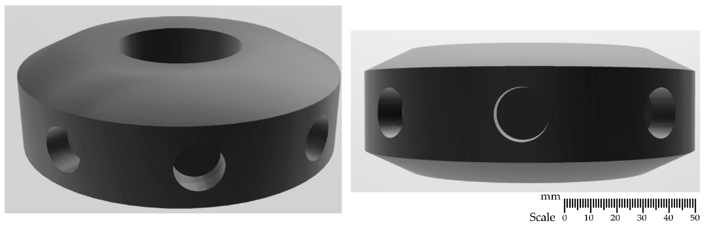
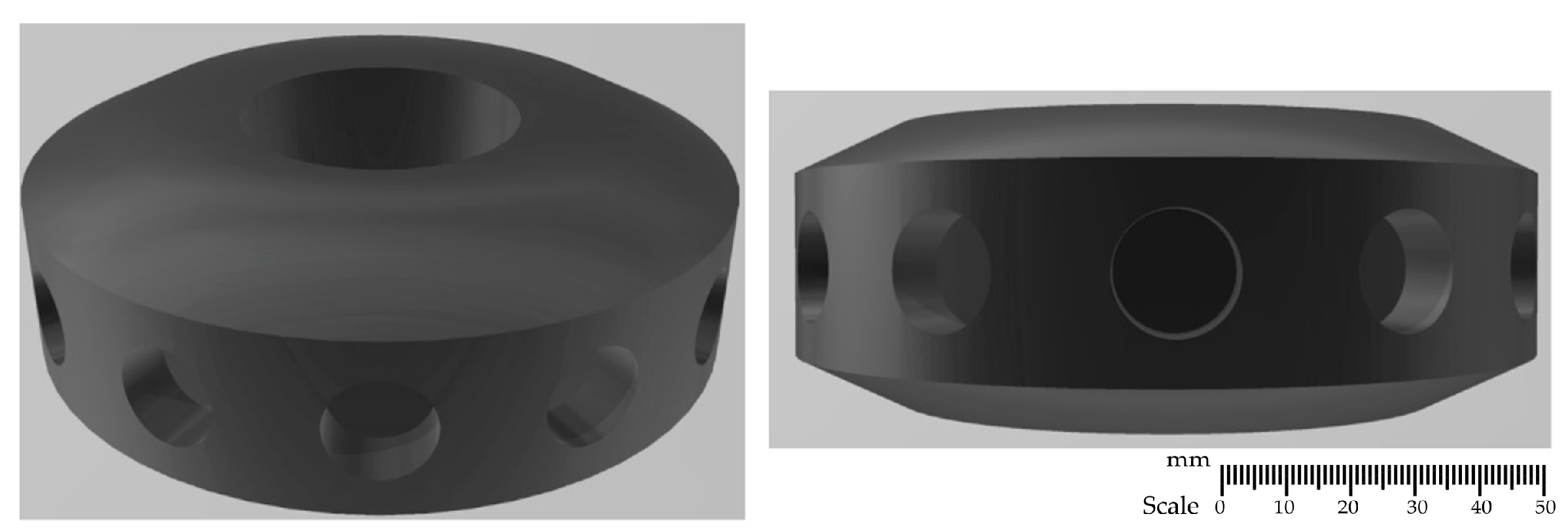
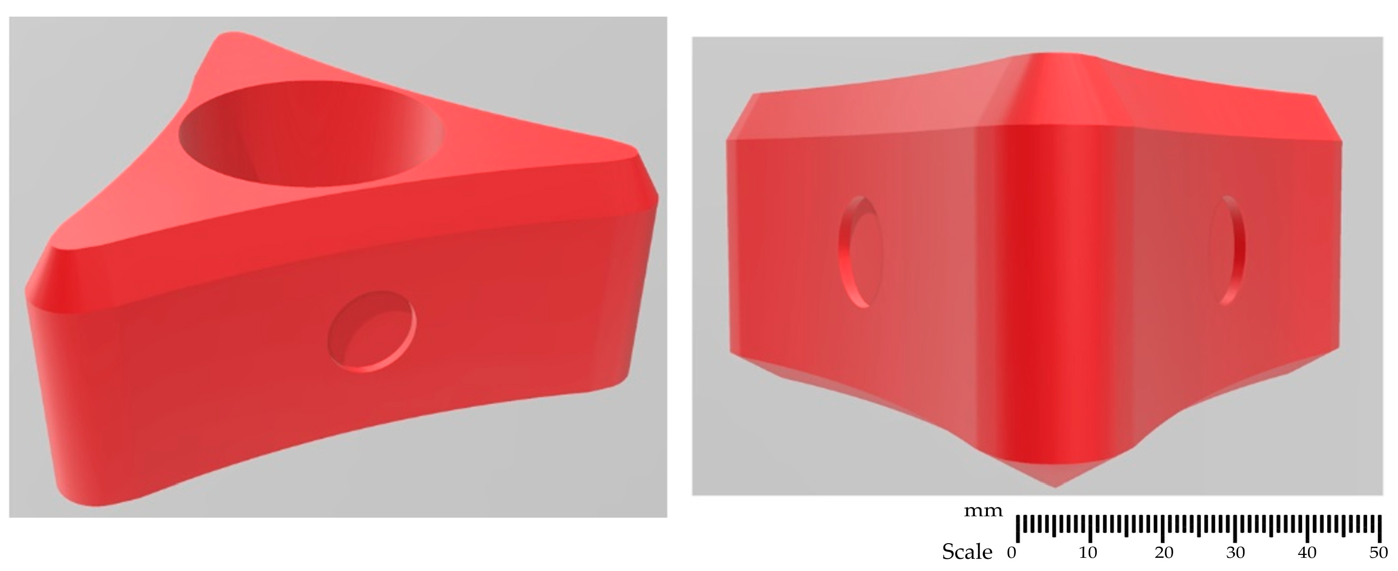
2.1. Rotor Designs
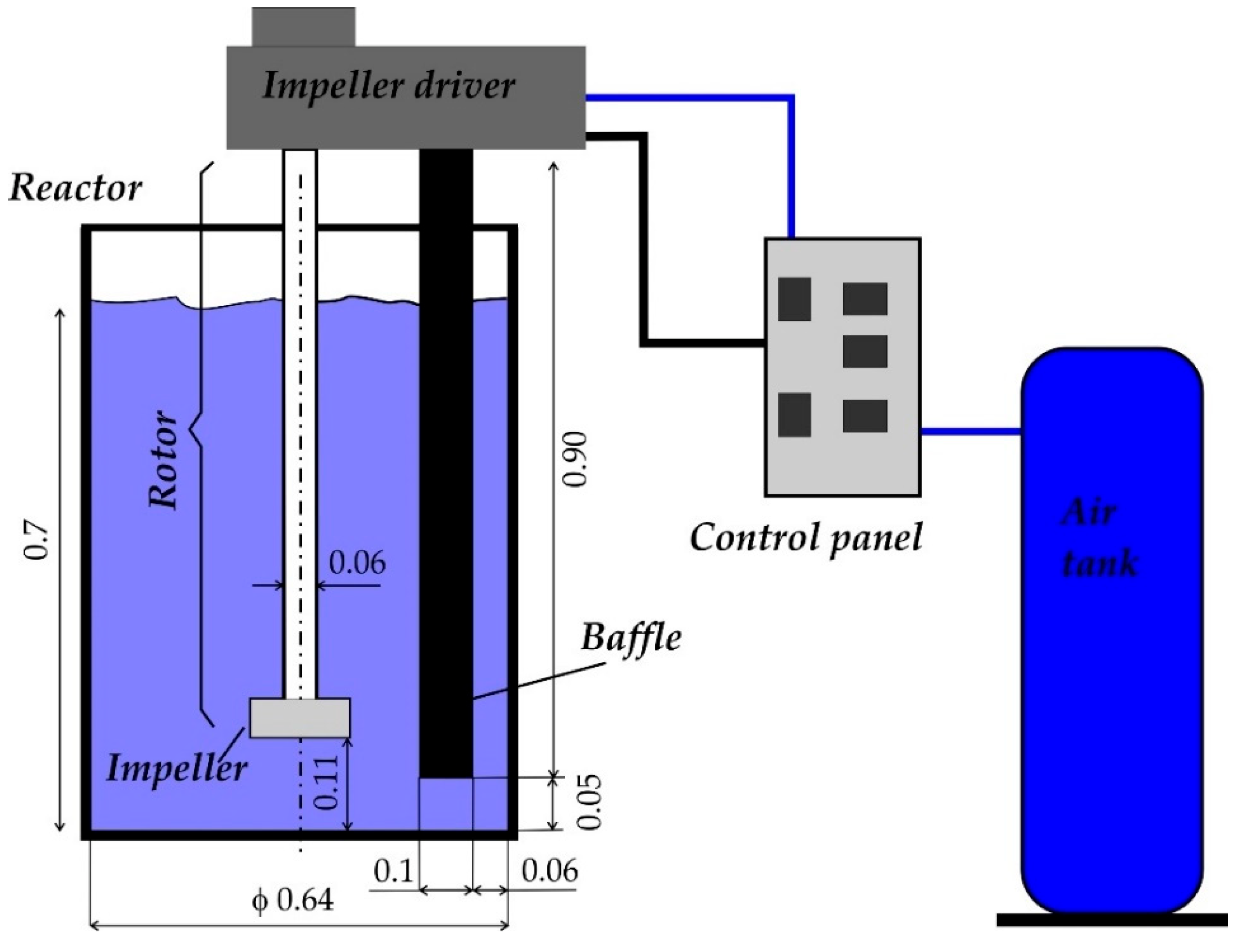
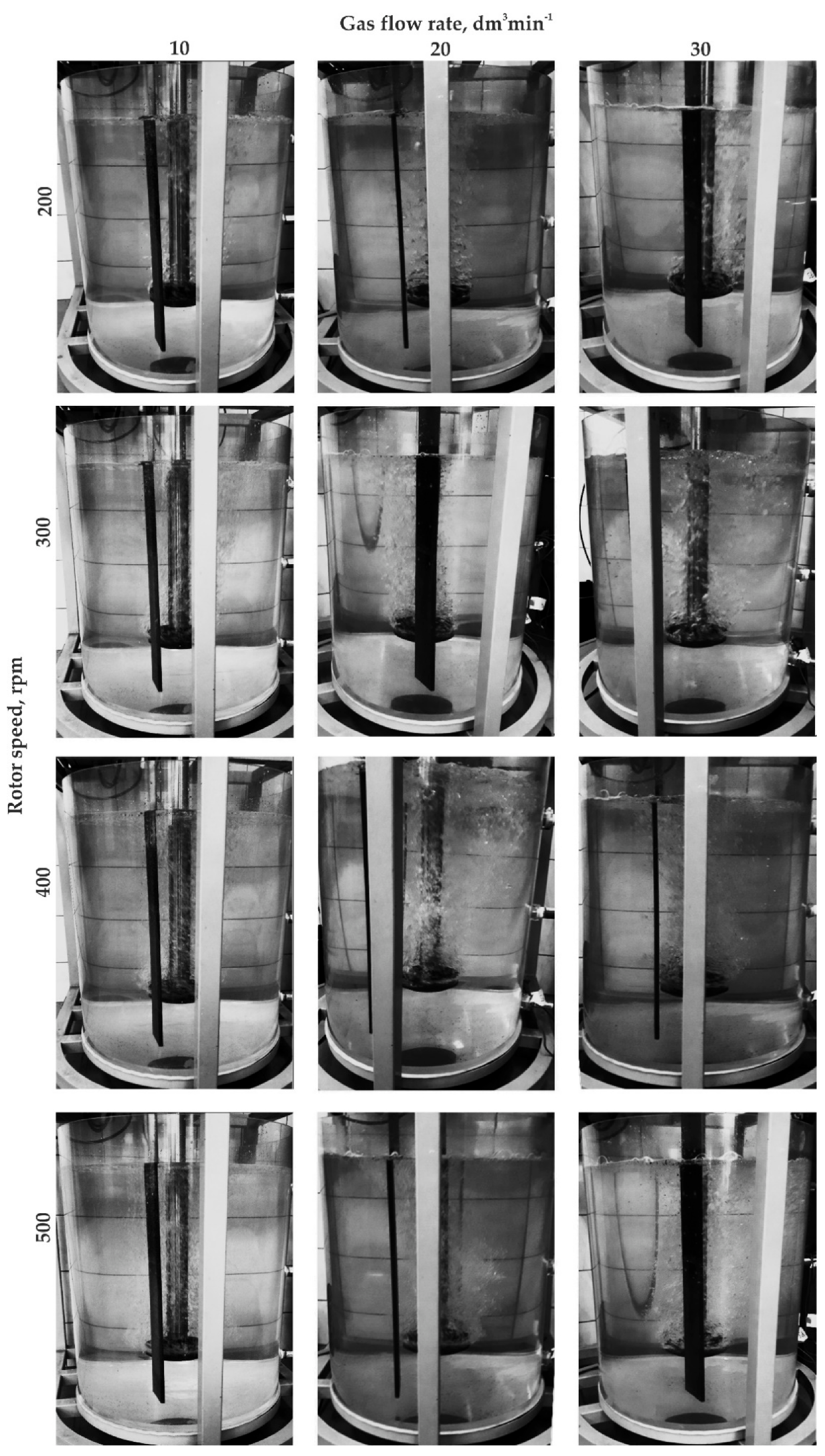
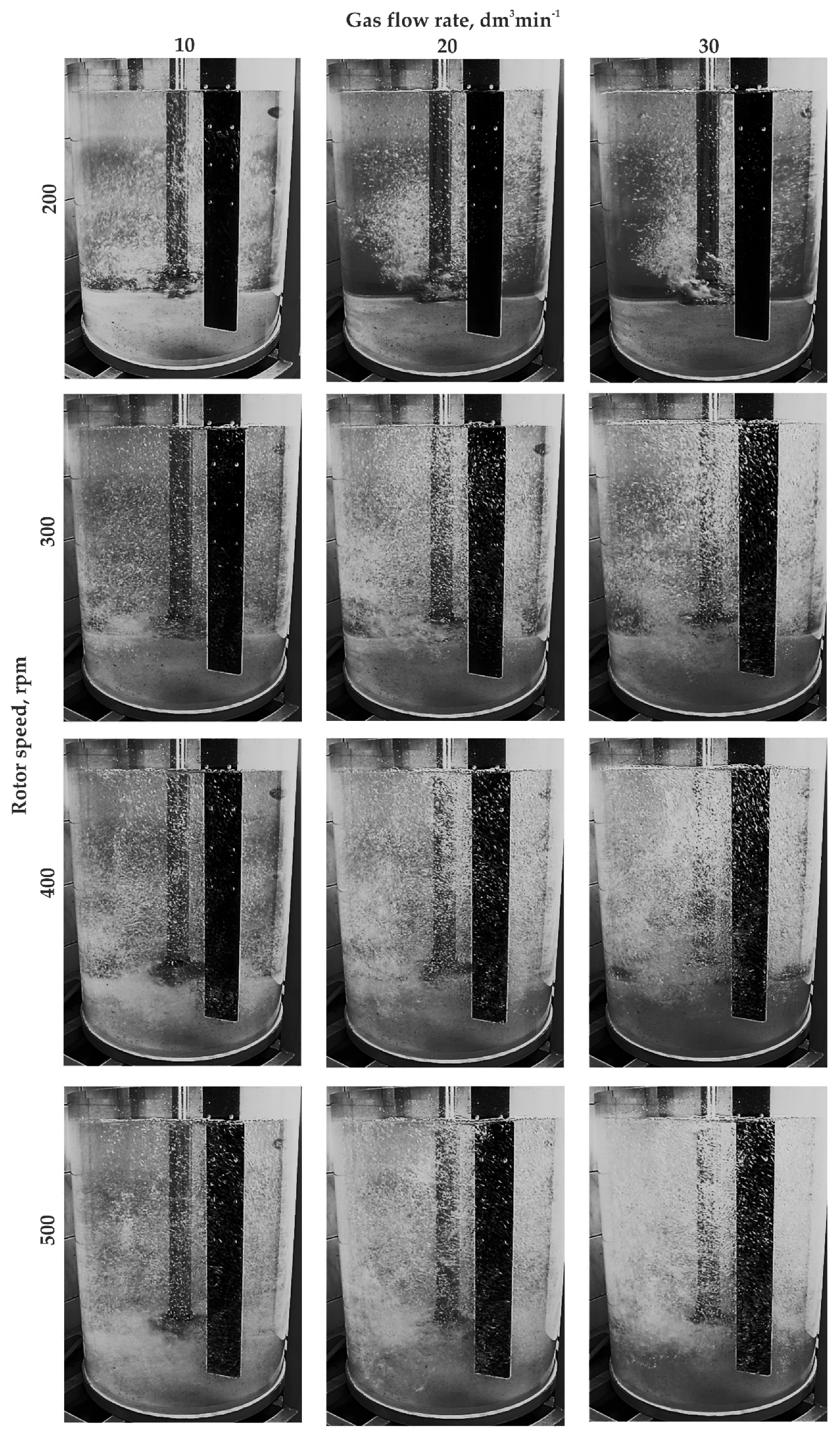
2.2. Physical Models
- URO-200XR—used for small crucible furnaces, the capacity of which does not exceed 250 kg, with no control system and no control of the refining process.
- URO-200SA—used to service several crucible furnaces of capacity from 250 kg to 700 kg, fully automated and equipped with a mechanical rotor lift.
- URO-200KA—used for refining processes in crucible furnaces and allows refining in a ladle. The process is fully automated, with a hydraulic rotor lift.
- URO-200KX—a combination of the XR and KA models, designed for the ladle refining process. Additionally, refining in heated crucibles is possible. The unit is equipped with a manual hydraulic rotor lift.
- URO-200PA—designed to cooperate with induction or crucible furnaces or intermediate chambers, the capacity of which does not exceed one ton. This unit is an integral part of the furnace. The rotor lift is equipped with a screw drive.
- Rotor speed: 200, 300, 400, and 500 rpm,
- Ideal gas flow: 10, 20, and 30 dm3·min−1,
- Temperature: 293 K (20 °C).
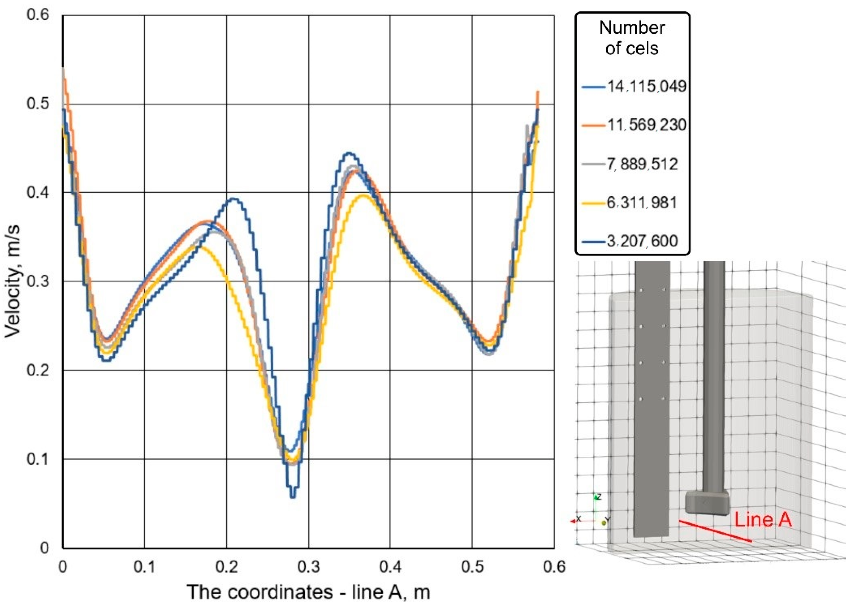
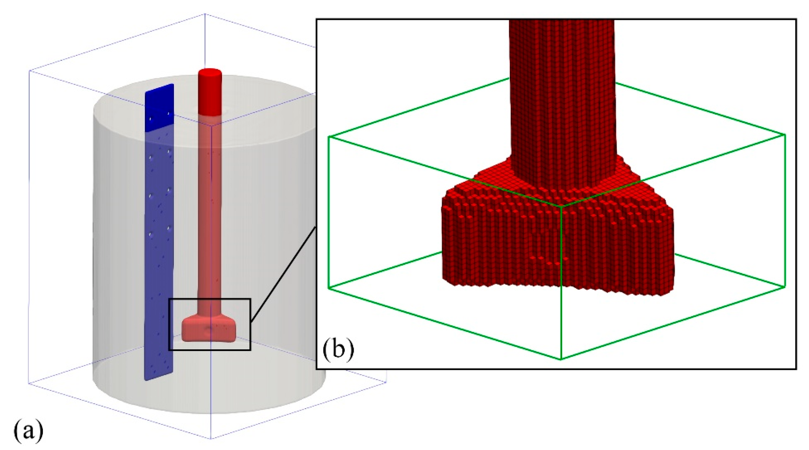
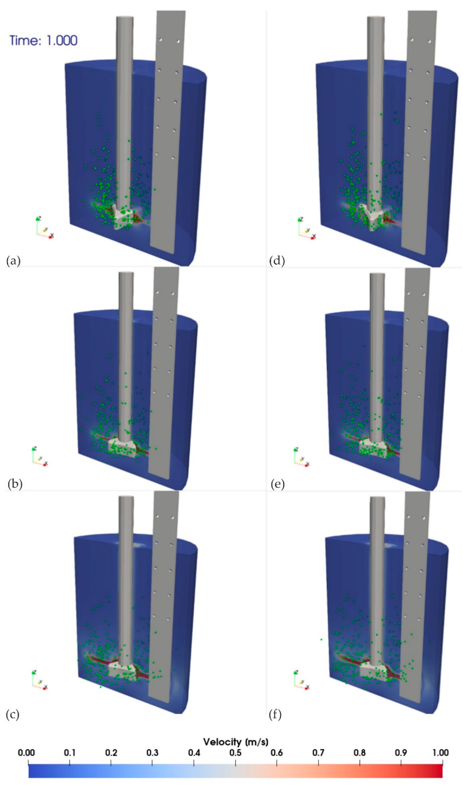
2.3. Numerical Simulations with Flow-3D Program
- —
- The liquid phase was considered as an incompressible Newtonian fluid.
- —
- The effect of chemical reactions during the refining process was neglected.
- —
- The composition of each phase (gas and liquid) was considered homogeneous; therefore, the viscosity and surface tension were set as constants.
- —
- Only full turbulence existed in the liquid, and the effect of molecular viscosity was neglected.
- —
- The gas bubbles were shaped as perfect spheres.
- —
- The mutual interaction between gas bubbles (particles) was neglected.
2.3.1. Modeling of Liquid Flow
2.3.2. Modeling of Gas Bubble Flow
3. Results and Discussion
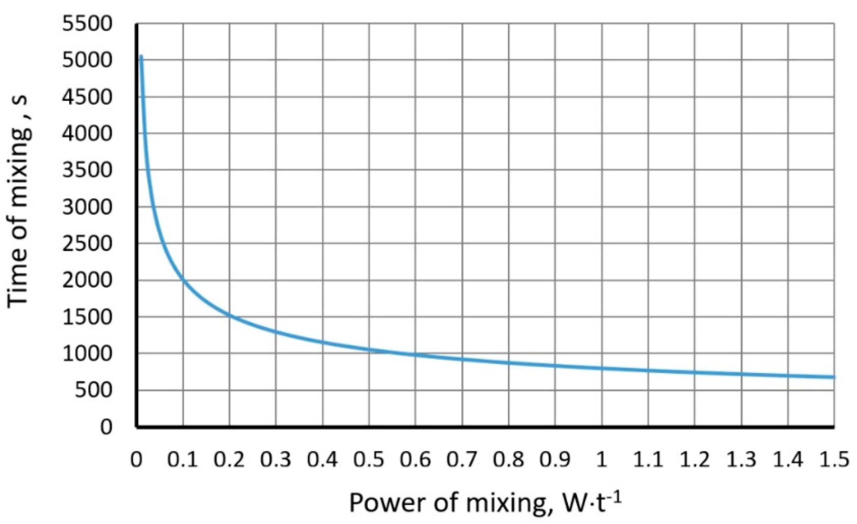
3.1. Calculations of Power and Mixing Time by the Flowing Gas Bubbles
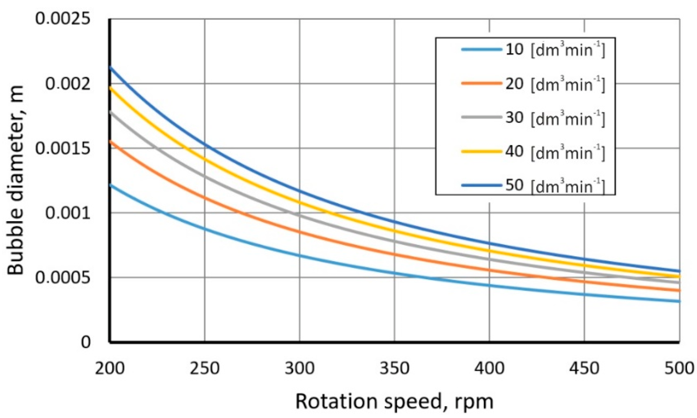
3.2. Determining the Bubble Size
- —
- Sevik and Park:
- —
- Evans:
3.3. Physical Modeling
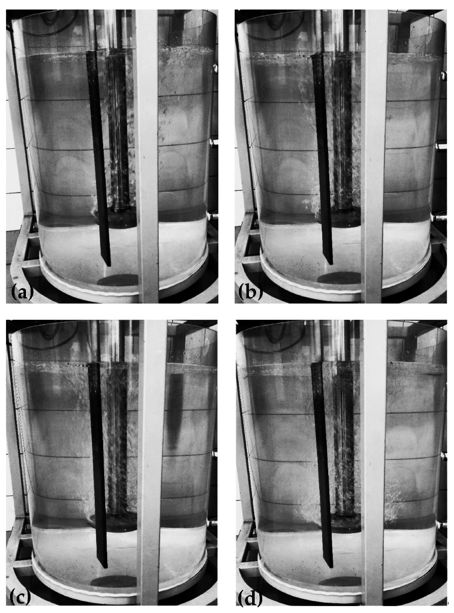
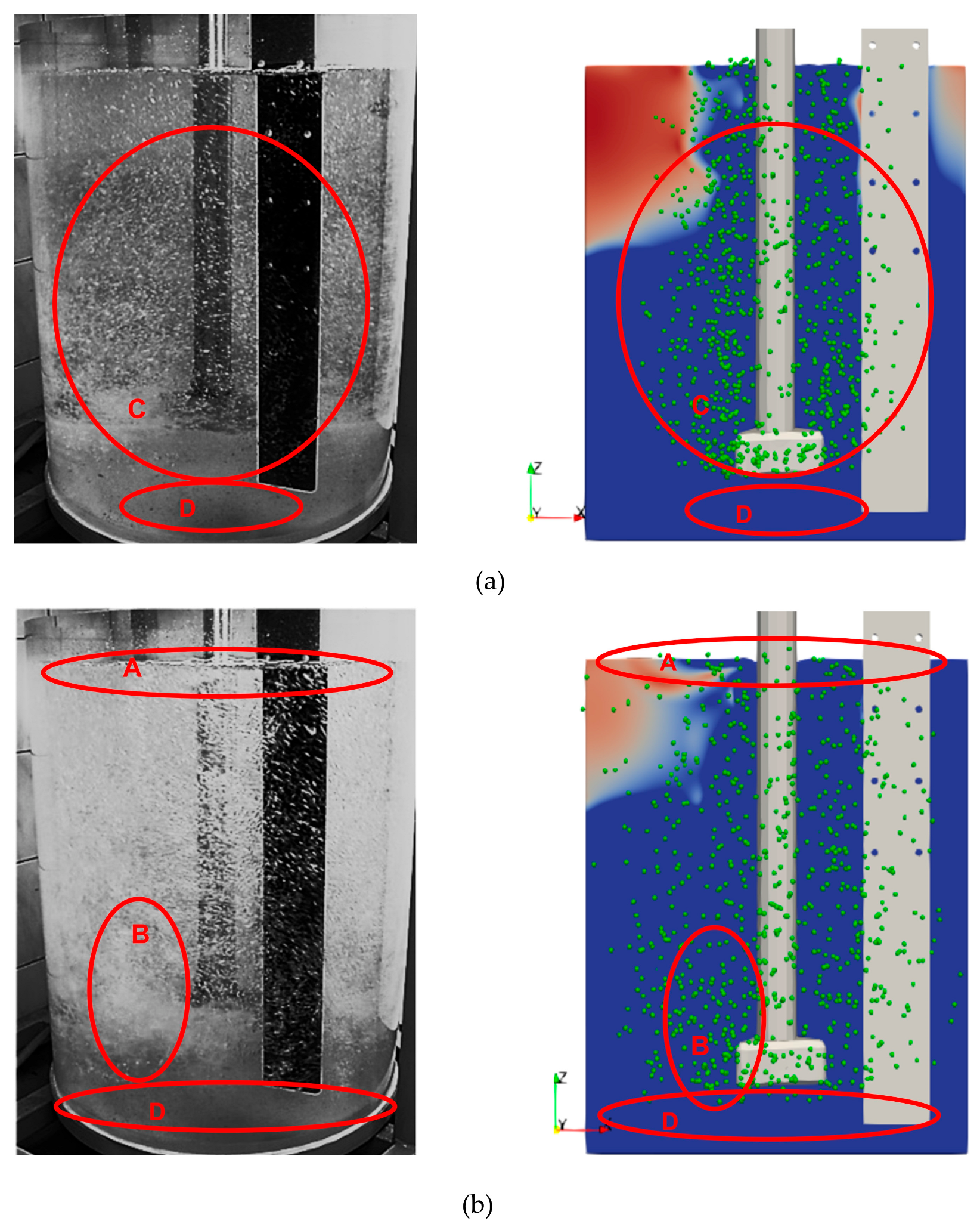
3.4. Qualitative Comparison of Research Results (CFD and Physical Model)
- Minimal dispersion—single bubbles ascending in the region of their formation along the ladle axis; lack of mixing in the whole bath volume.
- Accurate dispersion—single and well-mixed bubbles ascending toward the bath mirror in the region of the ladle axis; no dispersion near the walls and in the lower part of the ladle.
- Uniform dispersion—most desirable; very good mixing of fine bubbles with model liquid.
- Excessive dispersion—bubbles join together to form chains; large turbulence zones; uneven flow of gas.
4. Conclusions
Author Contributions
Funding
Institutional Review Board Statement
Informed Consent Statement
Data Availability Statement
Conflicts of Interest
References
- Zhang, L.; Xuewei, L.; Torgerson, A.T.; Long, M. Removal of Impurity Elements from Molten Aluminium: A Review. Miner. Process. Extr. Metall. Rev. 2011, 32, 150–228. [Google Scholar] [CrossRef]
- Saternus, M. Impurities of liquid aluminium-methods on their estimation and removal. Met. Form. 2015, 23, 115–132. [Google Scholar]
- Żak, P.L.; Kalisz, D.; Lelito, J.; Gracz, B.; Szucki, M.; Suchy, J.S. Modelling of non-metallic particle motion process in foundry alloys. Metalurgija 2015, 54, 357–360. [Google Scholar]
- Kalisz, D.; Kuglin, K. Efficiency of aluminum oxide inclusions rmoval from liquid steel as a result of collisions and agglomeration on ceramic filters. Arch. Foundry Eng. 2020, 20, 43–48. [Google Scholar]
- Kuglin, K.; Kalisz, D. Evaluation of the usefulness of rotors for aluminium refining. IOP Conf. Ser. Mater. Sci. Eng. 2021, 1178, 012036. [Google Scholar] [CrossRef]
- Saternus, M.; Merder, T. Physical modeling of the impeller construction impact o the aluminium refining process. Materials 2022, 15, 575. [Google Scholar] [CrossRef]
- Saternus, M.; Merder, T. Physical modelling of aluminum refining process conducted in batch reactor with rotary impeller. Metals 2018, 8, 726. [Google Scholar] [CrossRef] [Green Version]
- Saternus, M.; Merder, T.; Pieprzyca, J. The influence of impeller geometry on the gas bubbles dispersion in uro-200 reactor—RTD curves. Arch. Metall. Mater. 2015, 60, 2887–2893. [Google Scholar] [CrossRef]
- Hernández-Hernández, M.; Camacho-Martínez, J.; González-Rivera, C.; Ramírez-Argáez, M.A. Impeller design assisted by physical modeling and pilot plant trials. J. Mater. Process. Technol. 2016, 236, 1–8. [Google Scholar] [CrossRef]
- Mancilla, E.; Cruz-Méndez, W.; Garduño, I.E.; González-Rivera, C.; Ramírez-Argáez, M.A.; Ascanio, G. Comparison of the hydrodynamic performance of rotor-injector devices in a water physical model of an aluminum degassing ladle. Chem. Eng. Res. Des. 2017, 118, 158–169. [Google Scholar] [CrossRef]
- Michalek, K.; Socha, L.; Gryc, K.; Tkadleckova, M.; Saternus, M.; Pieprzyca, J.; Merder, T. Modelling of technological parameters of aluminium melt refining in the ladle by blowing of inert gas through the rotating impeller. Arch. Metall. Mater. 2018, 63, 987–992. [Google Scholar]
- Walek, J.; Michalek, K.; Tkadlecková, M.; Saternus, M. Modelling of Technological Parameters of Aluminium Melt Refining in the Ladle by Blowing of Inert Gas through the Rotating Impeller. Metals 2021, 11, 284. [Google Scholar] [CrossRef]
- Michalek, K.; Gryc, K.; Moravka, J. Physical modelling of bath homogenization in argon stirred ladle. Metalurgija 2009, 48, 215–218. [Google Scholar]
- Michalek, K. The Use of Physical Modeling and Numerical Optimization for Metallurgical Processes; VSB: Ostrawa, Czech Republic, 2001. [Google Scholar]
- Chen, J.; Zhao, J. Bubble distribution in a melt treatment water model. In Light Metals; TMS: Warrendale, PA, USA, 1995; pp. 1227–1231. [Google Scholar]
- Saternus, M. Model Matematyczny do Sterowania Procesem Rafinacji Ciekłych Stopów Aluminium Przy Zastosowaniu URO-200; Research Project Nr 7 T08B 019 21; Katowice, Poland, 2004. [Google Scholar]
- Pietrewicz, L.; Wężyk, W. Urządzenia do rafinacji gazowej typu URO-200 sześć lat produkcji i doświadczeń. In Proceedings of the Aluminum Conference, Zakopane, Poland, 12–16 October 1998. [Google Scholar]
- Flow3d User’s Guide; Flow Science, Inc.: Santa Fe, NM, USA, 2020.
- Sinelnikov, V.; Szucki, M.; Merder, T.; Pieprzyca, J.; Kalisz, D. Physical and numerical modeling of the slag splashing process. Materials 2021, 14, 2289. [Google Scholar] [CrossRef]
- White, F. Fluid Mechanics; McGraw-Hill Series in Mechanical Engineering; McGraw-Hill: New York, NY, USA, 2010. [Google Scholar]
- Yang, Z.; Yang, L.; Cheng, T.; Chen, F.; Zheng, F.; Wang, S.; Guo, Y. Fluid Flow Characteristic of EAF Molten Steel with Different Bottom-Blowing Gas Flow Rate Distributions. ISIJ 2020, 60, 1957–1967. [Google Scholar] [CrossRef] [Green Version]
- Nichols, B.D.; Hirt, C.W. Methods for calculating multi-dimensional, transient free surface flows past bodies. In Proceedings of the First International Conference on Numerical Ship Hydrodynamics, Gaithersburg, MD, USA, 20–22 October 1975. [Google Scholar]
- Hirt, C.W.; Nichols, B.D. Volume of Fluid (VOF) Method for the Dynamics of Free Boundaries. J. Comput. Phys. 1981, 39, 201–255. [Google Scholar] [CrossRef]
- Szucki, M.; Suchy, J.S.; Lelito, J.; Malinowski, P.; Sobczyk, J. Application of the lattice Boltzmann method for simulation of the mold filling process in the casting industry. Heat Mass Transf. 2017, 53, 3421–3431. [Google Scholar] [CrossRef] [Green Version]
- Themelis, N.J.; Goyal, P. Gas injection in steelmaking. Candian Metall. Trans. 1983, 22, 313–320. [Google Scholar]
- Zhang, L.; Jing, X.; Li, Y.; Xu, Z.; Cai, K. Mathematical model of decarburization of ultralow carbon steel during RH treatment. J. Univ. Sci. Technol. Beijing 1997, 4, 19–23. [Google Scholar]
- Chiti, F.; Paglianti, A.; Bujalshi, W. A mechanistic model to estimate powder consumption and mixing time in aluminium industries. Chem. Eng. Res. Des. 2004, 82, 1105–1111. [Google Scholar] [CrossRef]
- Bouaifi, M.; Roustan, M. Power consumption, mixing time and homogenization energy in dual-impeller agitated gas-liquid reactors. Chem. Eng. Process. 2011, 40, 87–95. [Google Scholar] [CrossRef]
- Kang, J.; Lee, C.H.; Haam, S.; Koo, K.K.; Kim, W.S. Studies on the overall oxygen transfer rate and mixing time in pilot-scale surface aeration vessel. Environ. Technol. 2001, 22, 1055–1068. [Google Scholar] [CrossRef] [PubMed]
- Moucha, T.; Linek, V.; Prokopov, E. Gas hold-up, mixing time and gas-liquid volumetric mass transfer coefficient of various multiple-impeller configurations: Rushton turbine, pitched blade and techmix impeller and their combinations. Chem. Eng. Sci. 2003, 58, 1839–1846. [Google Scholar] [CrossRef]
- Szekely, J. Flow phenomena, mixing and mass transfer in argon-stirred ladles. Ironmak. Steelmak. 1979, 6, 285–293. [Google Scholar]
- Iguchi, M.; Nakamura, K.; Tsujino, R. Mixing time and fluid flow phenomena in liquids of varying kinematic viscosities agitated by bottom gas injection. Metall. Mat. Trans. 1998, 29, 569–575. [Google Scholar] [CrossRef]
- Hjelle, O.; Engh, T.A.; Rasch, B. Removal of Sodium from Aluminiummagnesium Alloys by Purging with Cl2; Aluminium-Verlag GmbH: Dusseldorf, Germany, 1985; pp. 343–360. [Google Scholar]
- Zhang, L.; Taniguchi, S. Fundamentals of inclusion removal from liquid steel by bubble flotation. Int. Mat. Rev. 2000, 45, 59–82. [Google Scholar] [CrossRef]


| Parameter | Value | Unit |
|---|---|---|
| Maximum number of gas particles | 1,000,000 | - |
| Rate of particle generation | 2000 | 1·s−1 |
| Specific gas constant | 287.058 | J·kg−1·K−1 |
| Atmospheric pressure | 1.013 × 10⁵ | Pa |
| Water density | 1000 | kg·m−3 |
| Water viscosity | 0.001 | kg·m−1·s−1 |
| Boundary condition on the walls | No-slip | - |
| Size of computational cell | 0.0034 | m |
| No | Rotor Speed (Rotational Speed) rpm | Bubbles Diameter m | Corresponding Gas Flow Rate dm3·min−1 | No | Rotor Speed (Rotational Speed) rpm | Bubbles Diameter m | Corresponding Gas Flow Rate dm3·min−1 |
|---|---|---|---|---|---|---|---|
| A | 200 | 0.016 | 10 | D | 200 | 0.02 | 30 |
| 0.008 | 0.01 | ||||||
| 0.032 | 0.04 | ||||||
| B | 300 | 0.016 | 10 | E | 300 | 0.02 | 30 |
| 0.008 | 0.01 | ||||||
| 0.032 | 0.04 | ||||||
| C | 500 | 0.016 | 10 | F | 500 | 0.02 | 30 |
| 0.008 | 0.01 | ||||||
| 0.032 | 0.04 |
| Method | Equations |
|---|---|
| Euler–Lagrange | Balance equation: FD (u − up) denotes the drag forces per mass unit of a bubble, and the expression for the drag coefficient FD is of the form The relative Reynolds number has the form On the other hand, the force resulting from the additional acceleration of the model fluid has the form where ug is the gas bubble velocity, u is the liquid velocity, dg is the bubble diameter, and CD is the drag coefficient. |
| Parameter | Value | Unit |
|---|---|---|
| Height of metal column | 0.7 | m |
| Density of aluminum | 2375 | kg·m−3 |
| Process duration | 20 | s |
| Gas temperature at the injection site | 940 | K |
| Cross-sectional area of ladle | 0.448 | m2 |
| Mass of liquid aluminum | 546.25 | kg |
| Volume of ladle | 0.23 | M3 |
| Temperature of liquid aluminum | 941.15 | K |
| Mathematical Model | Mixing Power (W·t−1) for a Given Inert Gas Flow (dm3·min−1) | ||
|---|---|---|---|
| 10 | 20 | 30 | |
| Themelis and Goyal | 11.49 | 23.33 | 35.03 |
| Zhang | 0.82 | 1.66 | 2.49 |
| Authors | Model | Remarks |
|---|---|---|
| Szekely [31] | ε—W·t−1 | |
| Chiti and Paglianti [27] | V—volume of reactor, m3 Ql—flow intensity, m3·s−1 | |
| Iguchi and Nakamura [32] | υ—kinematic viscosity, m2·s−1 D—diameter of ladle, m h—height of metal column, m Q—liquid flow intensity, m3·s−1 |
| Model | Mixing Energy ĺ (m2·s−3) | Weber Number (Wekr) | ||
|---|---|---|---|---|
| 0.59 | 1.0 | 1.2 | ||
| Zhang and Taniguchi dmax | 0.1 | 0.0167 | 0.0230 | 0.026 |
| 0.5 | 0.0088 | 0.0121 | 0.013 | |
| 1.0 | 0.0067 | 0.0091 | 0.010 | |
| 1.5 | 0.0057 | 0.0078 | 0.009 | |
| Sevik and Park dBmax | 0.1 | 0.265 | 0.36 | 0.41 |
| 0.5 | 0.139 | 0.19 | 0.21 | |
| 1.0 | 0.106 | 0.14 | 0.16 | |
| 1.5 | 0.090 | 0.12 | 0.14 | |
| Evans dBmax | 0.1 | 0.247 | 0.340 | 0.38 |
| 0.5 | 0.130 | 0.178 | 0.20 | |
| 1.0 | 0.098 | 0.135 | 0.15 | |
| 1.5 | 0.084 | 0.115 | 0.13 | |
| No Exp. | A | B | C | D | E | F |
|---|---|---|---|---|---|---|
| Gas flow rate, dm3·min−1 | 10 | 30 | ||||
| Impeller speed, rpm | 200 | 300 | 500 | 200 | 300 | 500 |
| Type of dispersion | Accurate | Uniform | Uniform/excessive | Minimal | Excessive | Excessive |
Publisher’s Note: MDPI stays neutral with regard to jurisdictional claims in published maps and institutional affiliations. |
© 2022 by the authors. Licensee MDPI, Basel, Switzerland. This article is an open access article distributed under the terms and conditions of the Creative Commons Attribution (CC BY) license (https://creativecommons.org/licenses/by/4.0/).
Share and Cite
Kuglin, K.; Szucki, M.; Pieprzyca, J.; Genthe, S.; Merder, T.; Kalisz, D. Physical and Numerical Modeling of the Impeller Construction Impact on the Aluminum Degassing Process. Materials 2022, 15, 5273. https://doi.org/10.3390/ma15155273
Kuglin K, Szucki M, Pieprzyca J, Genthe S, Merder T, Kalisz D. Physical and Numerical Modeling of the Impeller Construction Impact on the Aluminum Degassing Process. Materials. 2022; 15(15):5273. https://doi.org/10.3390/ma15155273
Chicago/Turabian StyleKuglin, Kamil, Michał Szucki, Jacek Pieprzyca, Simon Genthe, Tomasz Merder, and Dorota Kalisz. 2022. "Physical and Numerical Modeling of the Impeller Construction Impact on the Aluminum Degassing Process" Materials 15, no. 15: 5273. https://doi.org/10.3390/ma15155273
APA StyleKuglin, K., Szucki, M., Pieprzyca, J., Genthe, S., Merder, T., & Kalisz, D. (2022). Physical and Numerical Modeling of the Impeller Construction Impact on the Aluminum Degassing Process. Materials, 15(15), 5273. https://doi.org/10.3390/ma15155273