
Debonding of Thin Bonded Rubberised Fibre-Reinforced Cement-Based Repairs under Monotonic Loading: Experimental and Numerical Investigation

 , , , and
Abstract
:1. Introduction
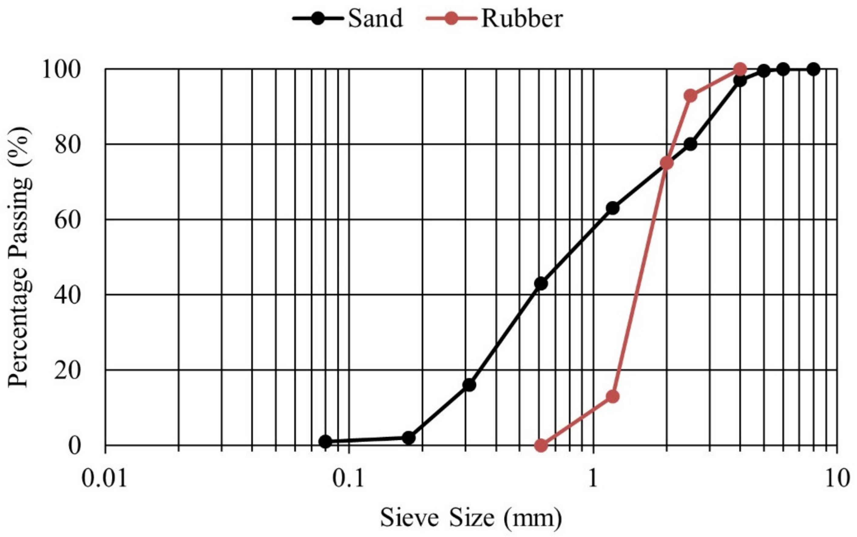
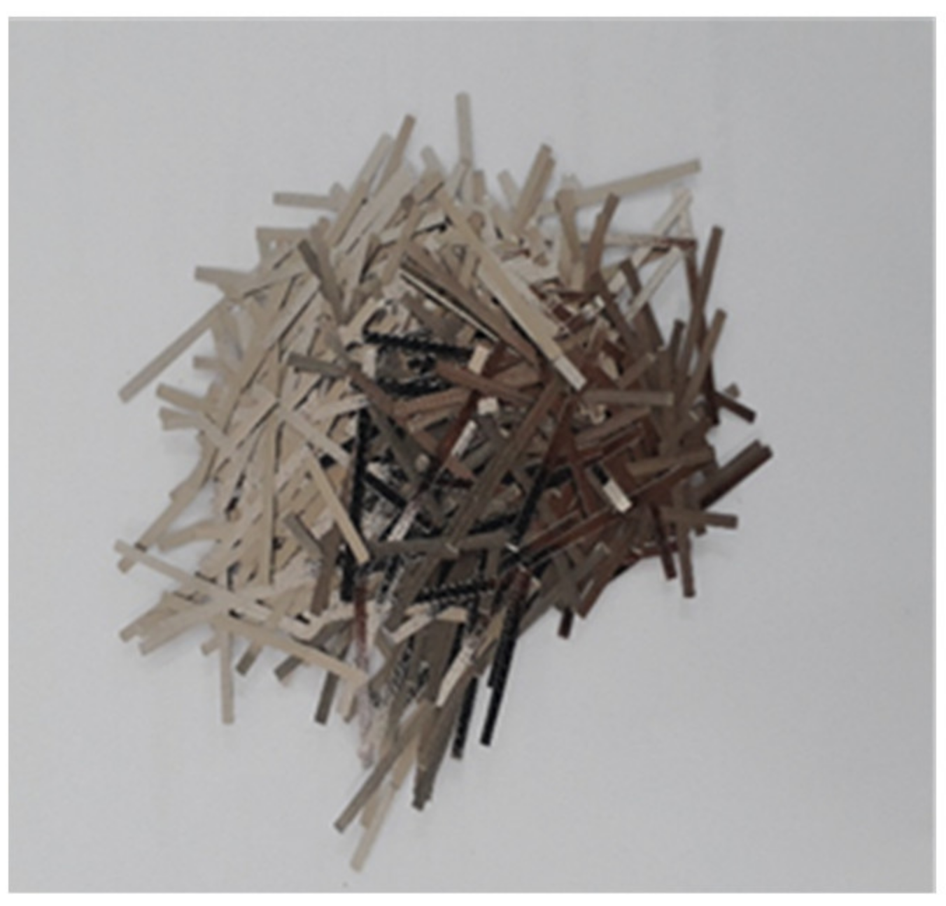
2. Materials
3. Mechanical Characterization
3.1. Compressive Tests
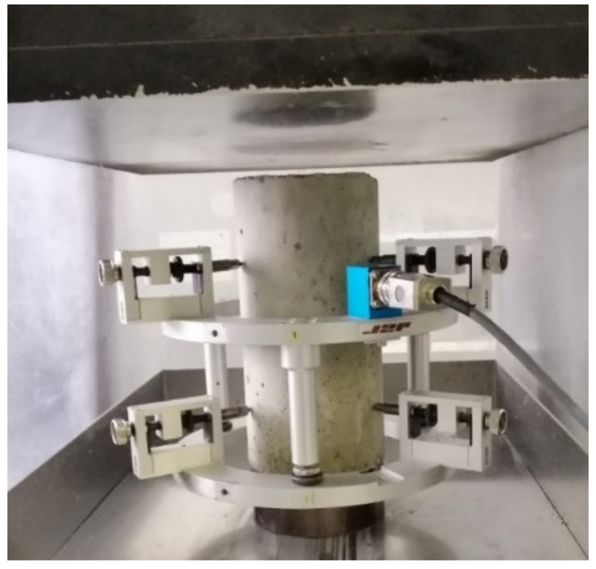
3.2. Modulus of Elasticity Tests
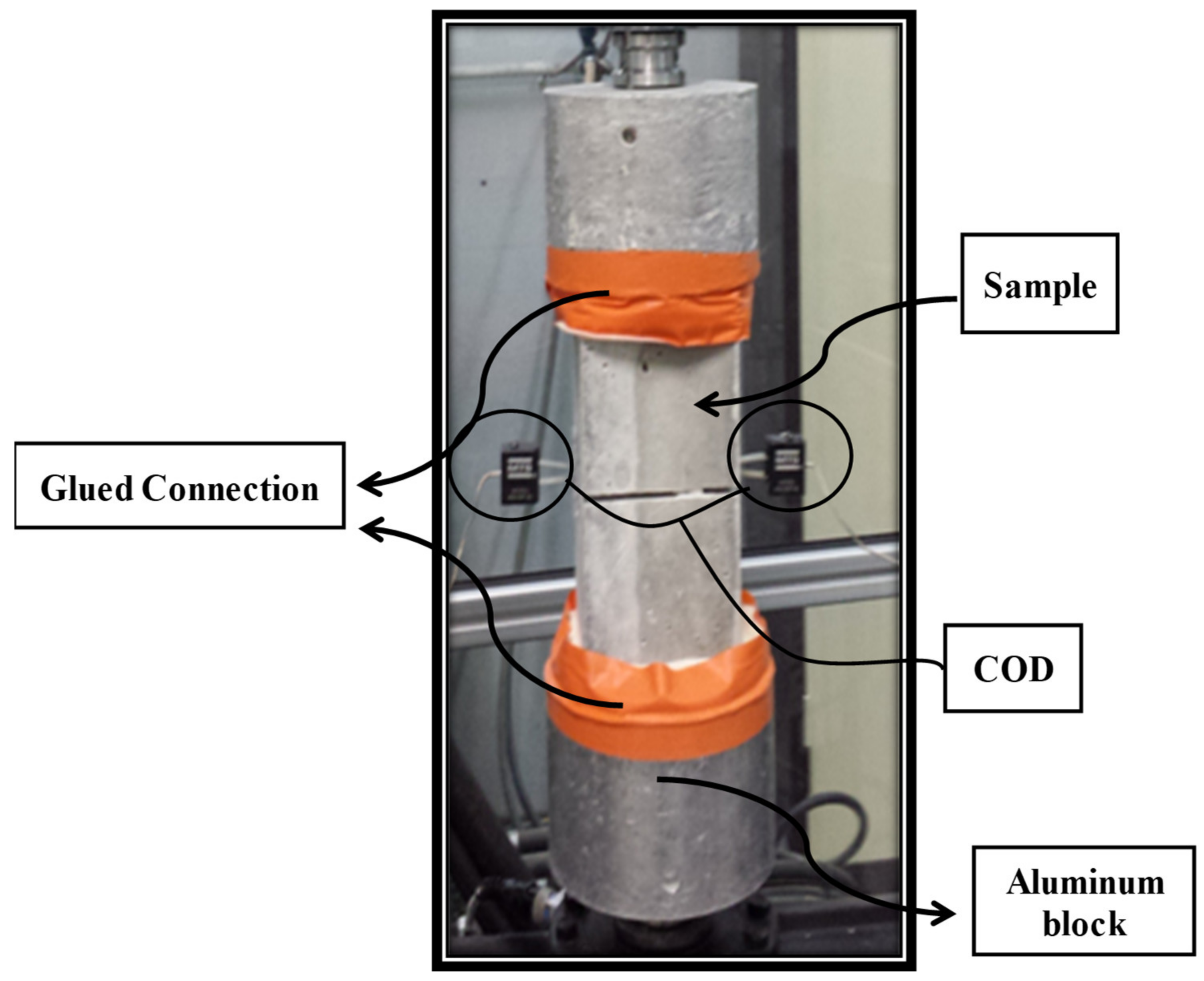
3.3. Direct Tensile Tests
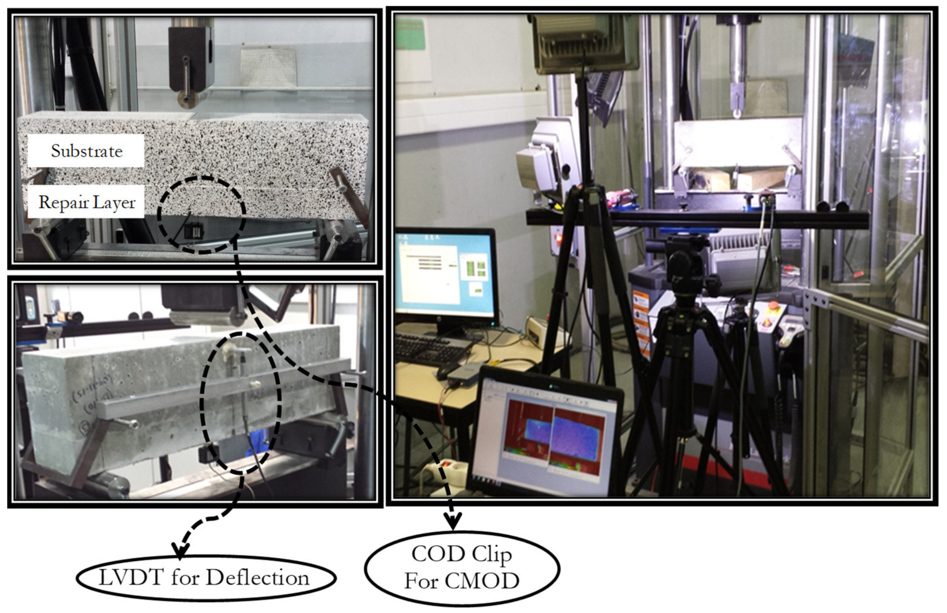
4. Bending Monotonic Test
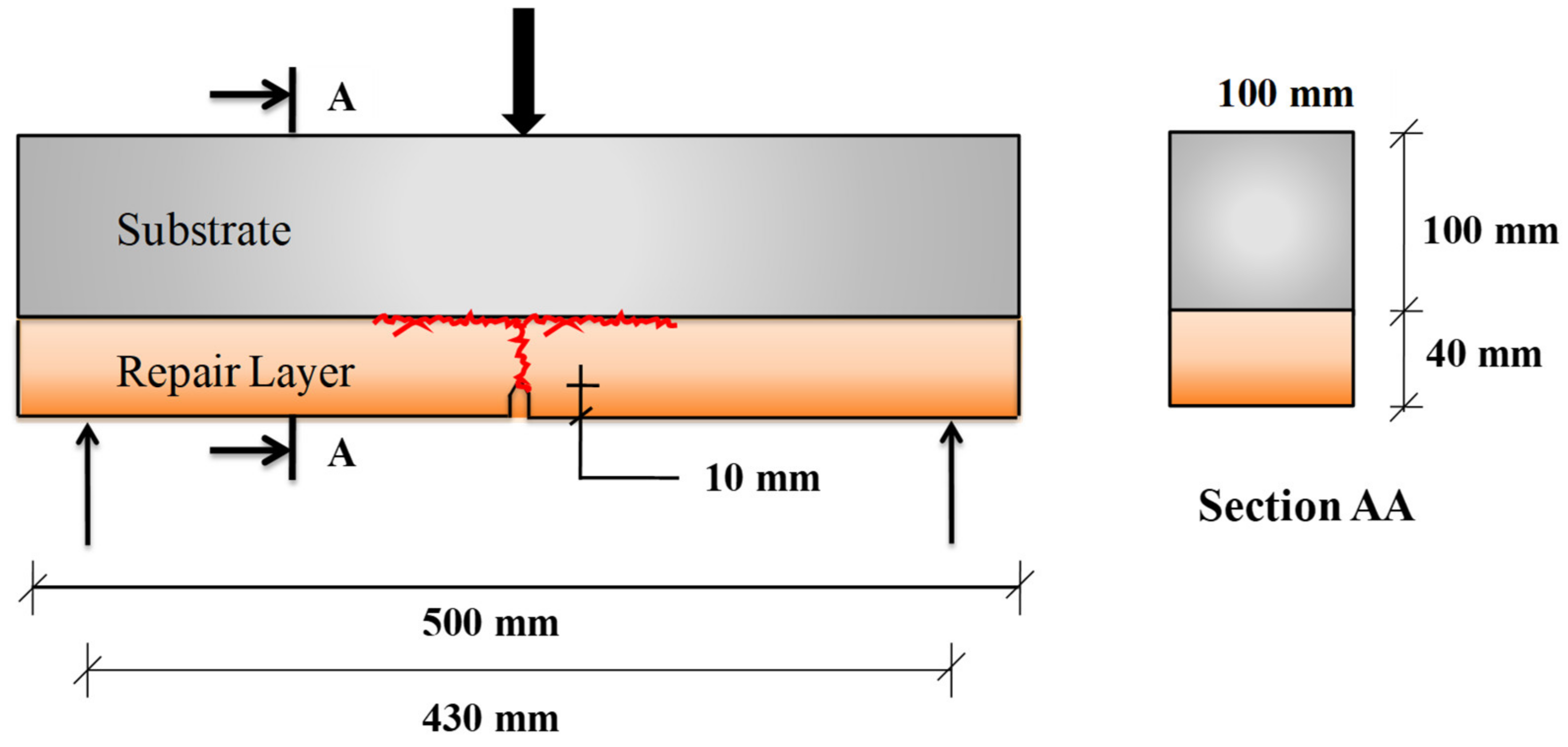
4.1. Specimen for the Monotonic Test
4.2. Testing Procedure
- The opening of the notch (CMOD) with the application of force.
- The deflection with force.
- The load at which the crack approaches the interface location with DIC.
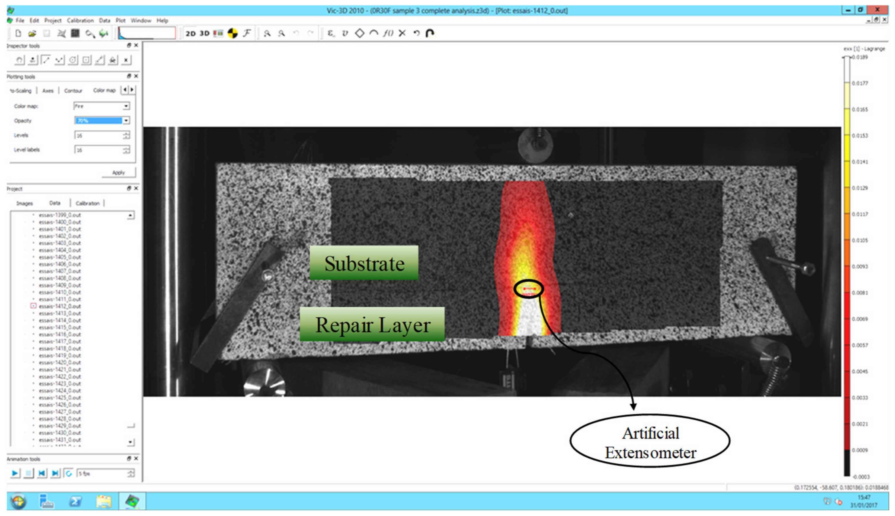
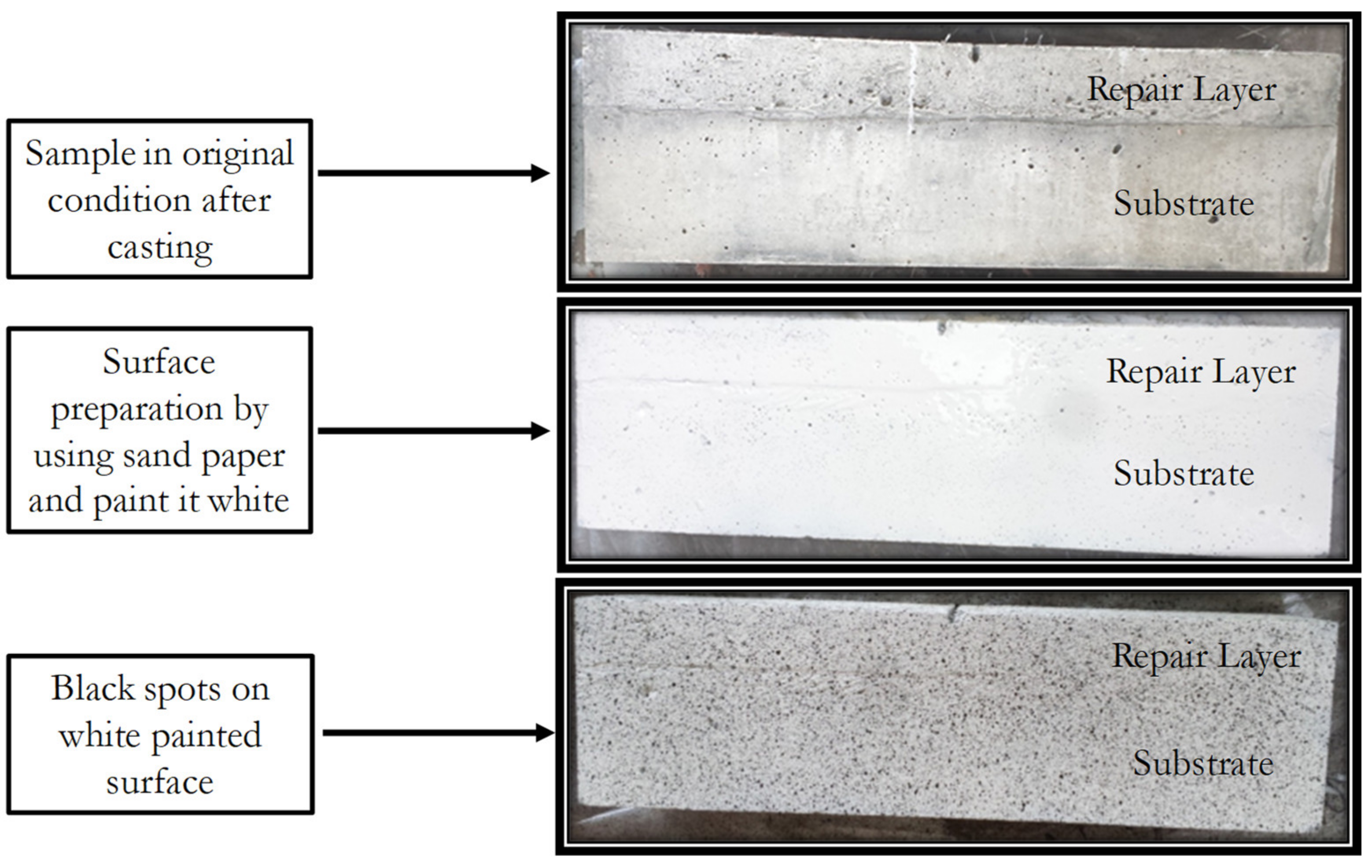
4.3. Digital Image Correlation Technique
5. Numerical Modelling
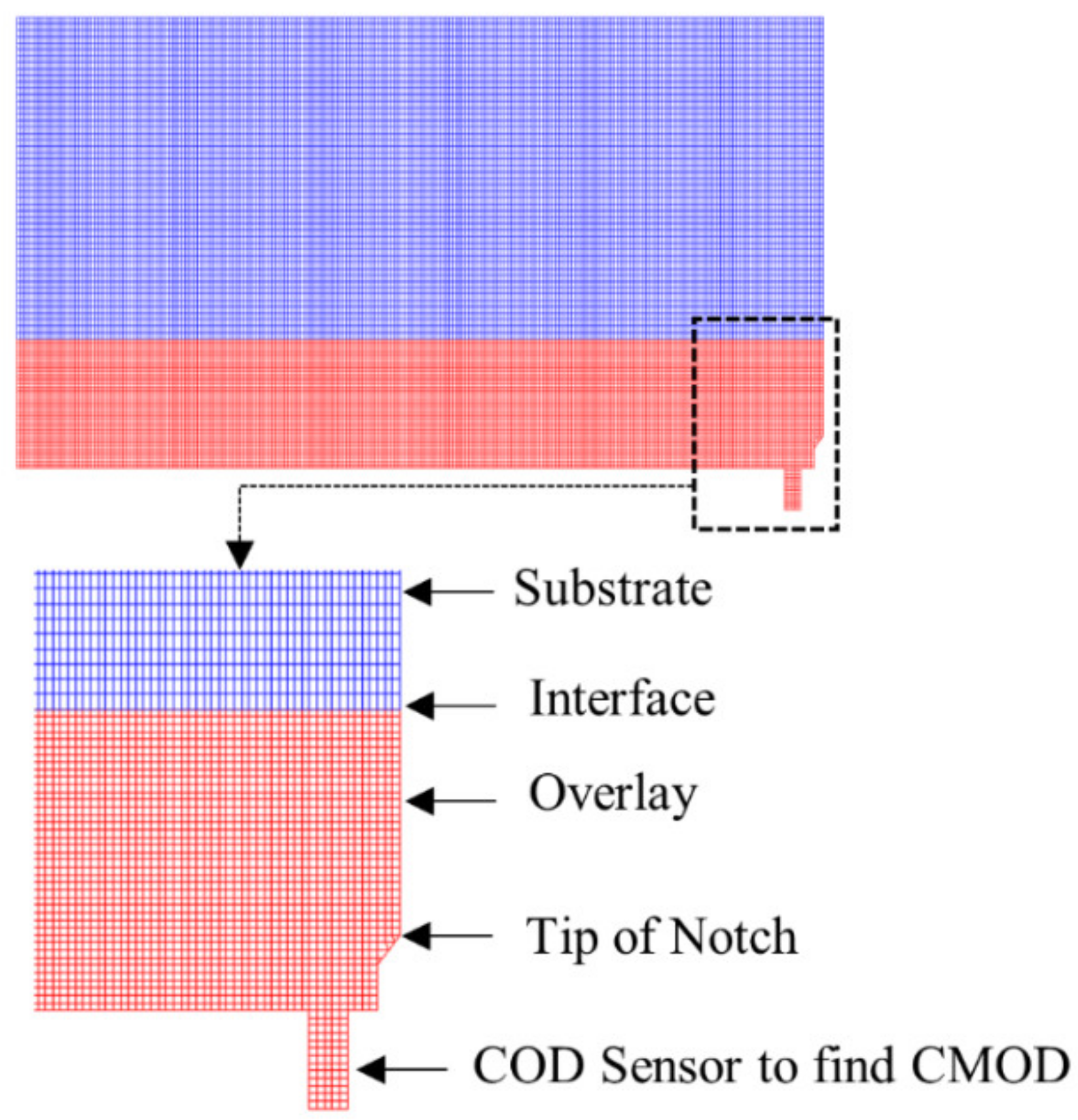
5.1. Mesh Size of Composite Beam
5.2. Cracking/Delamination Modelling Theory
- Debonding or cracks moved to the next node, if σt > Rt or σti > Rti, respectively, where σt is the tensile stress, Rt is the tensile strength of the repair materials and σti and Rti are the tensile stress and tensile strength of the substrate–repair interface, respectively.
- At the reach of stable state, and next step of increased loading was imposed to restart the propagation if the above-mentioned criterion is not met.
6. Results and Discussions
6.1. Modulus of Elasticity and Compressive Strength
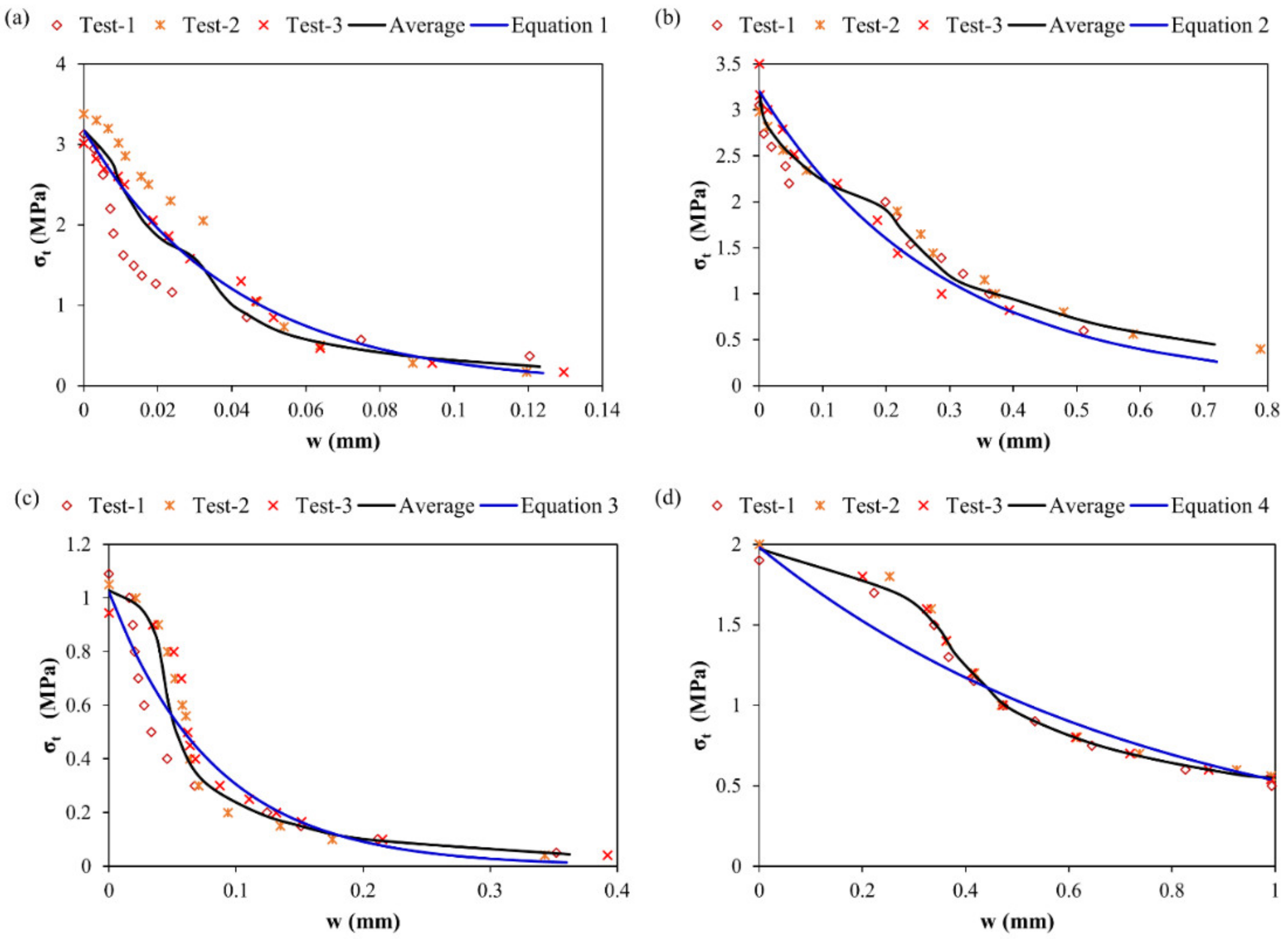
6.2. Tension Test for Material Used as Repair
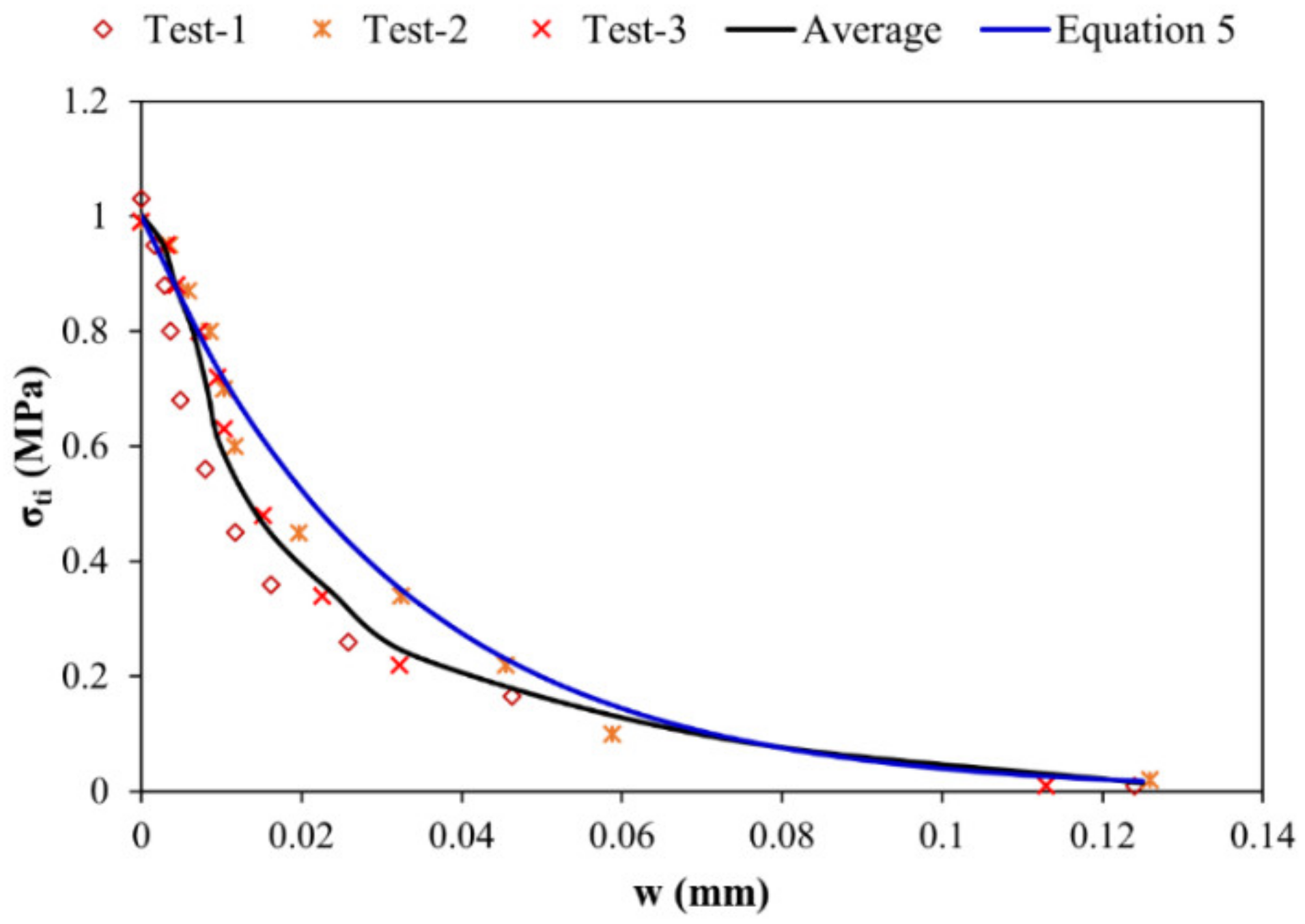
6.3. Tension Test for Overlay/Repair–Substrate Interface
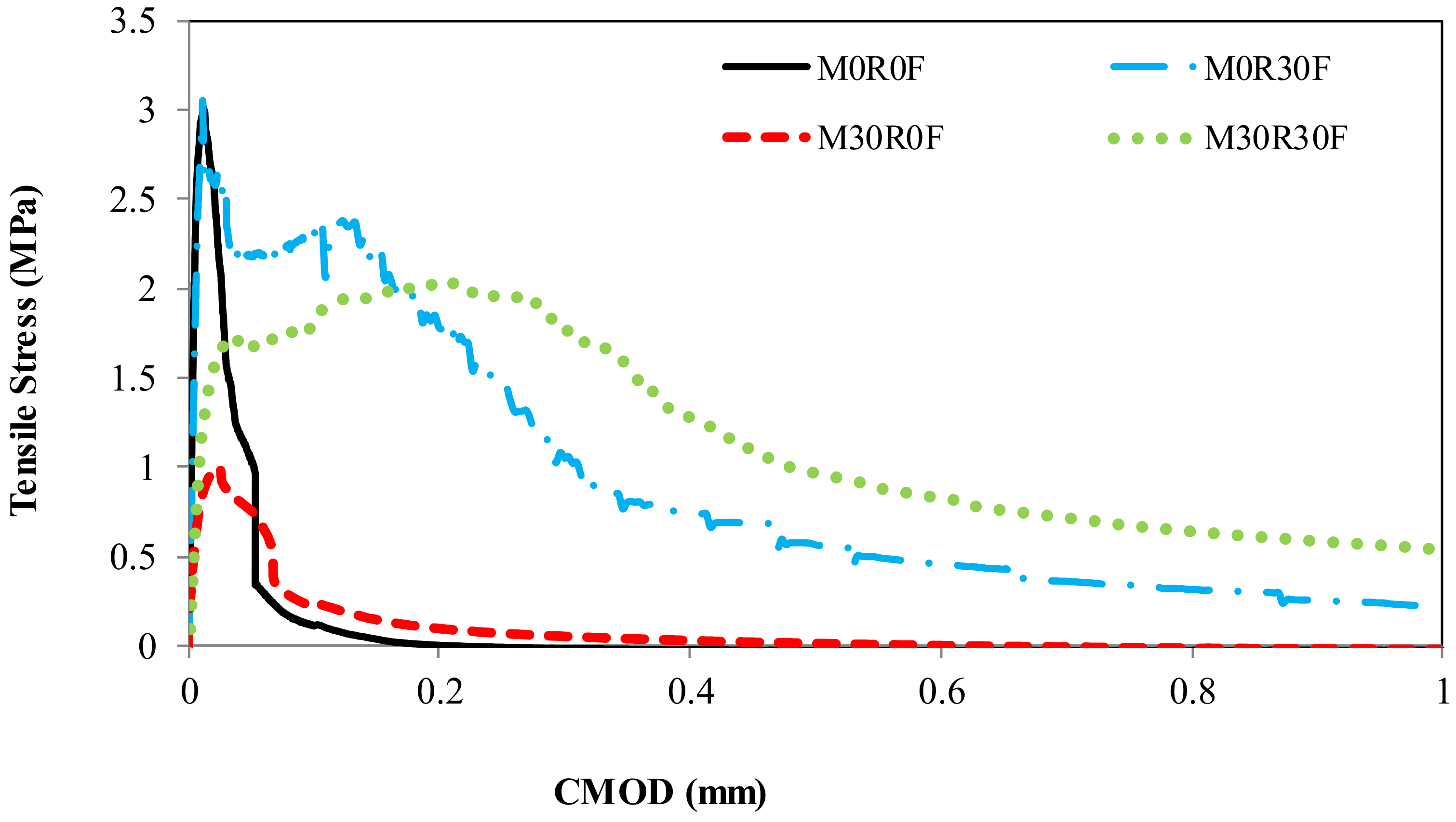
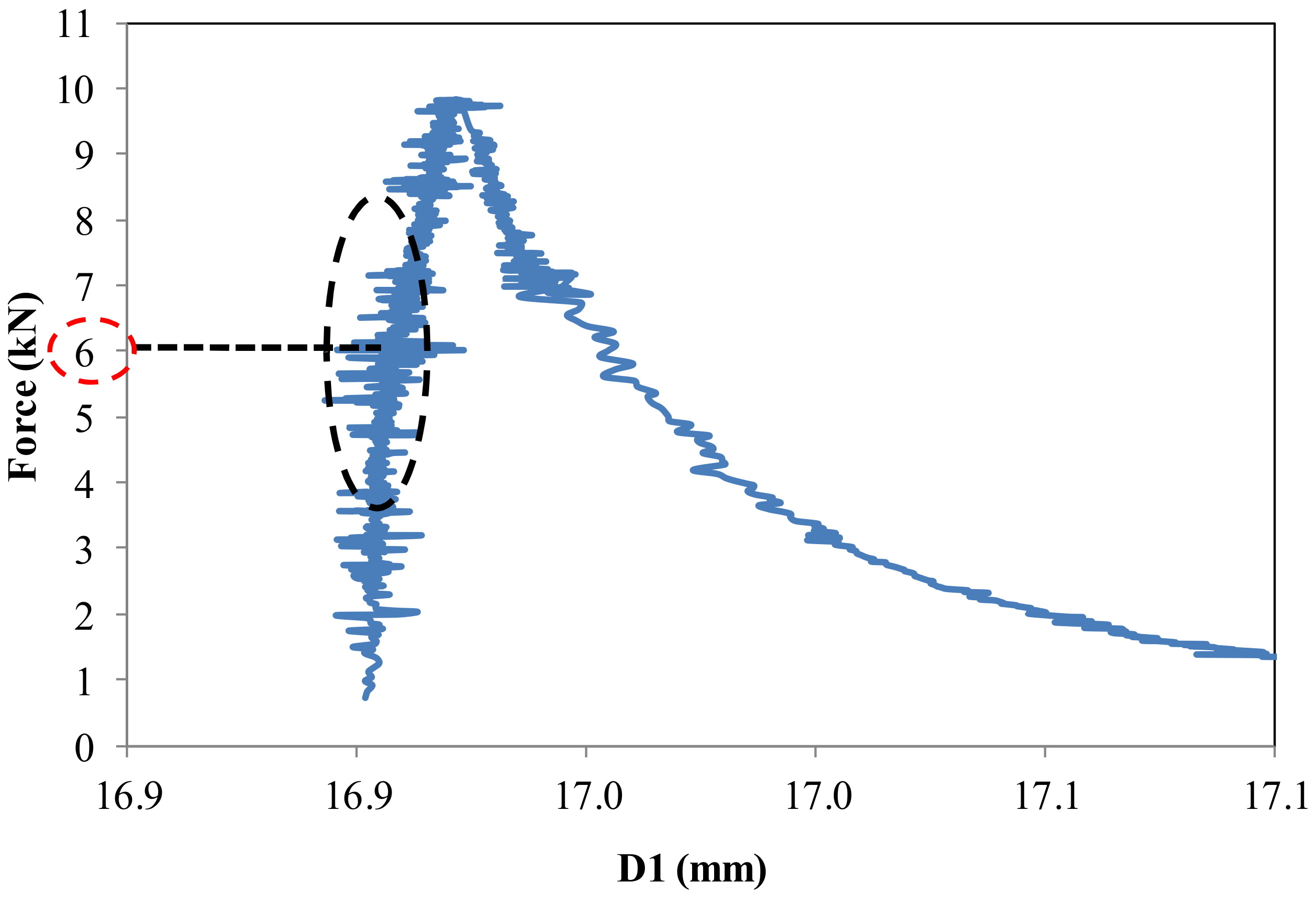
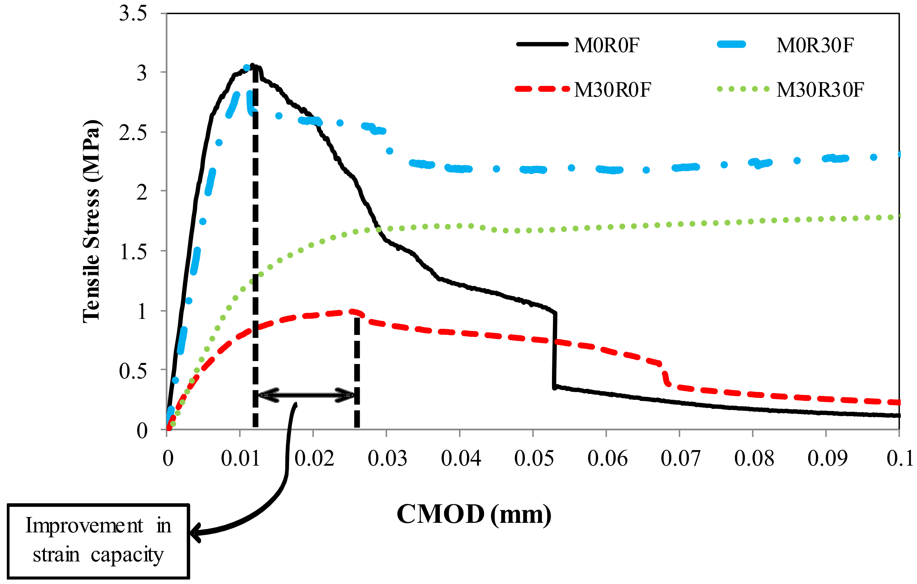
6.4. Relationship between Force and Opening of Notch
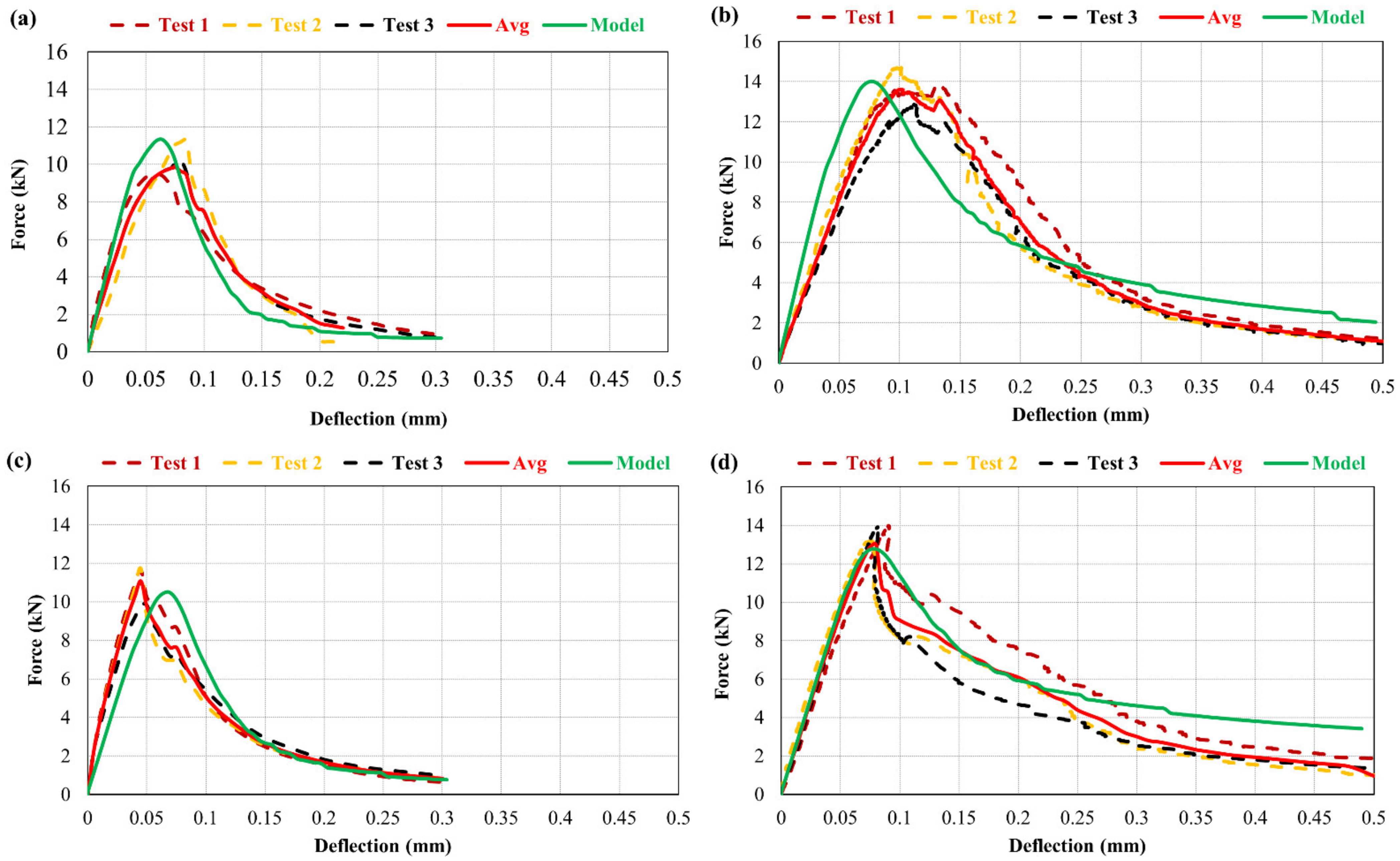
6.5. Relationship between Force and Deflection
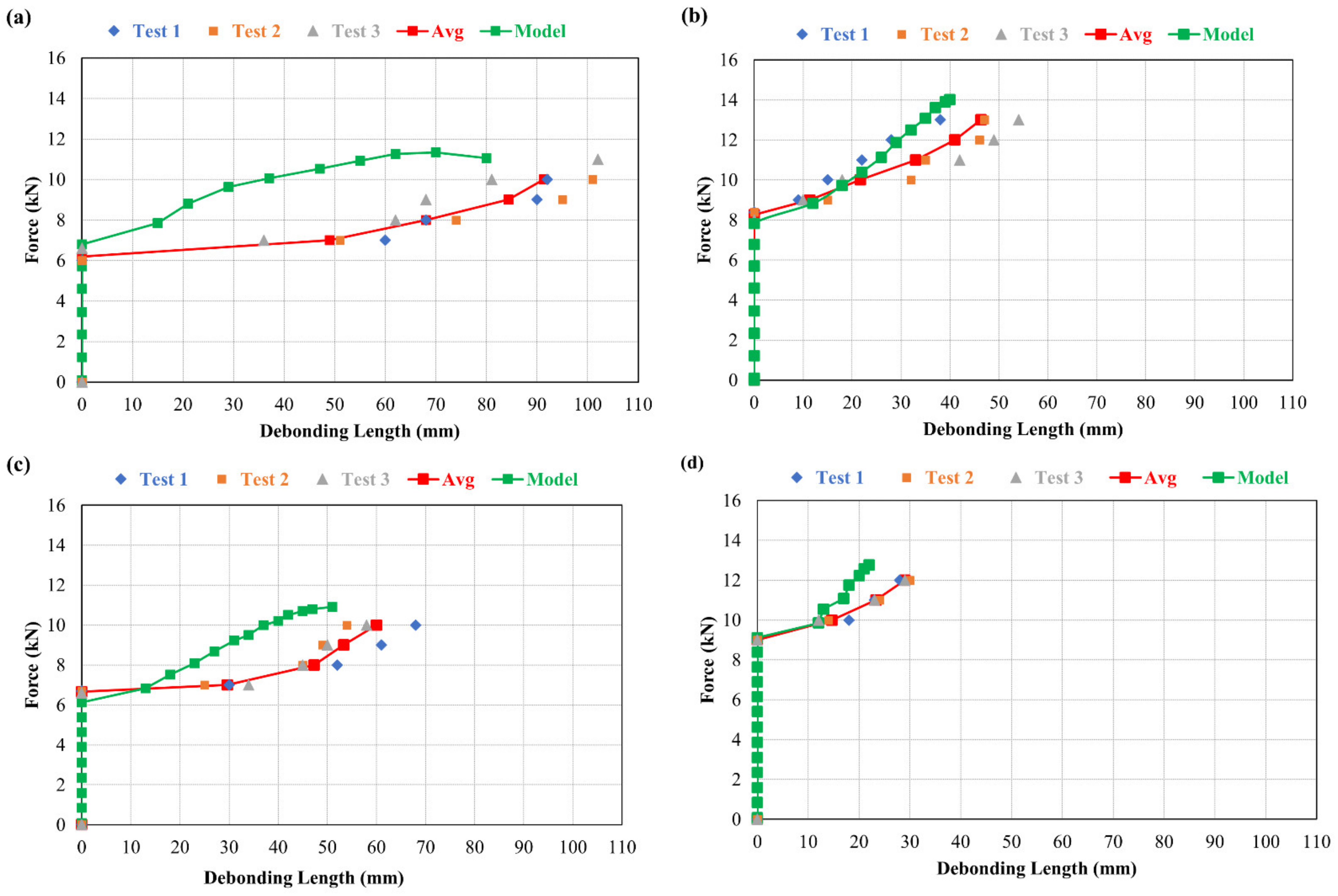
6.6. Relationship between Force and Debonding
7. Conclusions
- The maximum crack restraining was shown by repair material including fibres with or without the inclusion of rubber particles.
- To initiate the debonding, repair materials that are fibre-reinforced (either with or without rubber particles) required a greater value of load than the repair materials without the inclusion of fibres.
- M0R0F shows the minimum resistance to initiating interface debonding. However, for M30R0F repaired material, the transmission of delamination is restricted and retarded compared to the control one. The micro-cracking was controlled by rubber particles, which as a result increases and the load for debonding. Moreover, improved strain capacity of the repaired material with the addition of rubber particles also increases the notch opening at which the delamination starts.
- Debonding transmission at the interface is more significant in the materials without fibres (M0R0F or M30R0F) and is largely controlled in M30R30F repair. It shows the positive synergetic effect by the collective utilisation of rubber particles and fibres under static bending test.
- The FEM model results show that it accurately predicts the mechanical response of the material under monotonic flexure testing. In particular, it allows the kinetics of crack advancement and of delamination at the interface to be predicted.
- The developed FEM is an effective technique to predict and analyse the response of the repaired system under mechanical conditions of loading. In particular, it helps to highlight the benefit of incorporating rubber aggregates and fibre-reinforcement and the positive synergetic effect of both.
- The DIC technique is a suitable tool for the monitoring of debonding propagation along the interface.
- Finally, as added value to the contribution towards achieving more sustainable repair, the addition of rubber aggregates obtained through grinding of scrap tyres in cementitious materials can also be considered to maintain a clean environment by recycling used tyres and minimizing the use of landfill for residual waste.
Author Contributions
Funding
Institutional Review Board Statement
Data Availability Statement
Acknowledgments
Conflicts of Interest
References
- Bissonnette, B.; Courard, L.; Fowler, D.W.; Granju, J.-L. Bonded Cement-Based Material Overlays for the Repair, the Lining or the Strengthening of Slabs or Pavements; State-of-the-Art Report of the RILEM Technical Committee 193-RLS; Springer Science & Business Media: Berlin/Heidelberg, Germany, 2011; Volume 3. [Google Scholar]
- Chanvillard, G.; Aitcin, P.C.; Lupien, C. Field evaluation of steel-fiber reinforced concrete overlay with various bonding mechanisms. Transp. Res. Rec. 1989, 1226, 48–56. [Google Scholar]
- Granju, J.L. Thin bonded overlays: About the role of fiber reinforcement on the limitation of their debonding. Adv. Cem. Based Mater. 1996, 4, 21–27. [Google Scholar] [CrossRef]
- Tran, Q.T.; Toumi, A.; Granju, J.-L. Experimental and numerical investigation of the debonding interface between an old concrete and an overlay. Mater. Struct. 2006, 39, 379–389. [Google Scholar] [CrossRef]
- Langlois, M.; Pigeon, M.; Bissonnette, B.; Allard, D. Durability of pavement repairs field experiment. Concr. Int. 1994, 16, 39–43. [Google Scholar]
- Emmons, P.H.; Czarnecki, L.; Mcdonald, J.E.; Vaysburd, A.M. Durability of repair materials: Current practice and challenges. In Proceedings of the International Symposium on Brittle Matrix Composites, Warsaw, Poland, 9–11 October 2000; pp. 263–274. [Google Scholar]
- Gillani, A.A.S.; Toumi, A.; Turatsinze, A. Effect of incorporating rubber aggregates and fiber reinforcement on the durability of thin bonded cement-based overlays. In Proceedings of the 8th RILEM International Conference on Mechanisms of Cracking and Debonding in Pavements, Nantes, France, 7–9 June 2016; Springer: Berlin/Heidelberg, Germany, 2016; pp. 619–625. [Google Scholar]
- Gillani, S.A.A. Degradation of the residual strength of concrete: Effect of Fiber-Reinforcement and of Rubber Aggregates, Application to Thin Bonded Cement-Based Overlays. Ph.D. Thesis, Université de Toulouse, Université Toulouse III-Paul Sabatier, Toulouse, France, 2017. [Google Scholar]
- Ali Gillani, S.A.; Rizwan Riaz, M.; Hameed, R.; Qamar, A.; Toumi, A.; Turatsinze, A. Fracture Energy of Fiber-Reinforced and Rubberized Cement-Based Composites: A Sustainable Approach Towards Recycling of Waste Scrap Tires. 2022. Available online: https://journals.sagepub.com/doi/abs/10.1177/0958305X221089223 (accessed on 11 April 2022).
- Fiber-Reinforced and Rubberized Cement-Based Composite: A Sustainable Repair Material for Thin Bonded Overlays. Available online: https://scholar.google.com/citations?view_op=view_citation&hl=en&user=w8Ca5HIAAAAJ&sortby=pubdate&citation_for_view=w8Ca5HIAAAAJ:WF5omc3nYNoC (accessed on 24 April 2022).
- Nguyen, T.H.; Toumi, A.; Turatsinze, A. Mechanical properties of steel fibre reinforced and rubberised cement-based mortars. Mater. Des. 2010, 31, 641–647. [Google Scholar] [CrossRef]
- Toumi, A.; Nguyen, T.-H.; Turatsinze, A. Debonding of a thin rubberised and fibre-reinforced cement-based repairs: Analytical and experimental study. Mater. Des. 2013, 49, 90–95. [Google Scholar] [CrossRef]
- Nguyen, T.-H.; Toumi, A.; Turatsinze, A.; Tazi, F. Restrained shrinkage cracking in steel fibre reinforced and rubberised cement-based mortars. Mater. Struct. 2012, 45, 899–904. [Google Scholar] [CrossRef]
- Gillani, S.A.A.; Shahzad, S.; Toumi, A.; Turatsinze, A. Debonding of rubberised fibre-reinforced cement-based repairs under fatigue loading: Experimental study and numerical modelling. Int. J. Pavement Eng. 2021, 1–17. [Google Scholar] [CrossRef]
- Mateos, A.; Harvey, J.; Paniagua, J.; Paniagua, F.; Fan Liu, A. Mechanical characterisation of concrete-asphalt interface in bonded concrete overlays of asphalt pavements. Eur. J. Environ. Civ. Eng. 2017, 21, 43–53. [Google Scholar] [CrossRef]
- Isla Calderón, F.A.; Luccioni, B.M.; Ruano Sandoval, G.J.; Torrijos, M.C.; Morea, F.; Giaccio, G.M.; Zerbino, R.L. Mechanical response of fiber reinforced concrete overlays over asphalt concrete substrate: Experimental results and numerical simulation. Constr. Build. Mater. 2015, 93, 1022–1033. [Google Scholar] [CrossRef]
- Hasani, M.; Nejad, F.M.; Sobhani, J.; Chini, M. Mechanical and durability properties of fiber reinforced concrete overlay: Experimental results and numerical simulation. Constr. Build. Mater. 2021, 268, 121083. [Google Scholar] [CrossRef]
- Gillani, S.A.A.; Toumi, A.; Turatsinze, A. Effect of surface preparation of substrate on bond tensile strength of thin bonded cement-based overlays. Int. J. Pavement Res. Technol. 2020, 13, 197–204. [Google Scholar] [CrossRef]
- BS EN 197-1: 2011; Cement, Composition, Specifications and Conformity Criteria for Common Cements. British Standard Institution (BSI): London, UK, 2011.
- Shahzad, S.; Toumi, A.; Balayssac, J.-P.; Turatsinze, A.; Mazars, V. Cementitious composites incorporating Multi-Walled Carbon Nanotubes (MWCNTs): Effects of annealing and other dispersion methods on the electrical and mechanical properties. Matériaux Tech. 2022, 110, 104. [Google Scholar] [CrossRef]
- Fibraflex a New Generation of Metallic Fibers’. Available online: http://www.fibraflex.fr/sites/fibraflex.com/files/pdf/fibraflex_brochure_en_0.pdf (accessed on 11 April 2022).
- Balouch, S.U.; Granju, J.-L. Corrosion of different types of steel fibres in SFRC and testing of corrosion inhibitors. In Proceedings of the Infrastructure Regeneration and Rehabilitation Improving the Quality of Life through Better Construction: A vision for the Next Millennium, Sheffield, UK, 28 June–2 July 1999; pp. 735–747. [Google Scholar]
- Fiore, A.; Marano, G.C.; Marti, C.; Molfetta, M. On the fresh/hardened properties of cement composites incorporating rubber particles from recycled tires. Adv. Civ. Eng. 2014, 2014, 876158. [Google Scholar] [CrossRef]
- BS EN 12390-3; Essais pour Béton Durci–Partie 3: Résistance à la Compression des Éprouvettes [Tests for Hardened Concrete-Part 3: Compressive Strength of the Specimens]. British Standards Institution (BSI): London, UK, 2012.
- BS EN 12390-1; Testing hardened concrete–Part 1: Shape, dimensions and other requirements for specimens and moulds. British Standards Institution (BSI): London, UK, 2000.
- BS EN 12390-13; Testing Hardened Concrete–Part 13: Determination of Secant Modulus of Elasticity in Compression. British Standards Institution: London, UK, 2013.
- Vandewalle, L.; Nemegeer, D.; Balazs, G.L.; Barr, B.; Bartos, P.; Banthia, N.; Brandt, A.M.; Criswell, M.; Denarie, F.; Di Prisco, M. Rilem TC 162-TDF: Test and design methods for steel fibre reinforced concrete: Uni-axial tension test for steel fibre reinforced concrete. Mater. Struct. Mater. Et Constr. 2001, 34, 3–6. [Google Scholar]
- Chausson, H. La Durabilité des Rechargements Minces Adhérents en Béton Renforcé de Fibres Métalliques. Ph.D. Thesis, Université Paul Sabatier, Toulouse, France, 1997. [Google Scholar]
- Courard, L.; Piotrowski, T.; Garbacz, A. Near-to-surface properties affecting bond strength in concrete repair. Cem. Concr. Compos. 2014, 46, 73–80. [Google Scholar] [CrossRef]
- Farhat, H. Durabilité des Réparations en Béton de Fibres: Effets du Retrait et de la Fatigue. Ph.D. Thesis, Université Paul Sabatier, Toulouse, France, 1999. [Google Scholar]
- Garbacz, A.; Courard, L.; Kostana, K. Characterization of concrete surface roughness and its relation to adhesion in repair systems. Mater. Charact. 2006, 56, 281–289. [Google Scholar] [CrossRef]
- Grandhaie, F. Le Béton de Fibres Métalliques Amorphes Comme Nouveau Matériau de Réparation. Ph.D. Thesis, Université Paul Sabatier, Toulouse, France, 1993. [Google Scholar]
- Silfwerbrand, J. Improving concrete bond in repaired bridge decks. Concr. Int. 1990, 12, 61–66. [Google Scholar]
- Tran, Q.T. Interface ancien-nouveau béton: Caractérisation du Comportement Adoucissant de L’interface au Cours de Décollement et son Évolution dans le cas de Sollicitation de Fatigue. Ph.D. Thesis, Université Paul Sabatier, Toulouse, France, 2006. [Google Scholar]
- Nguyen, T.-H. Durabilité des Réparations à Base Cimentaire: Analyse Comparée de L’influence des Propriétés Mécaniques du Matériau de Réparation. Ph.D. Thesis, Université de Toulouse, Université Toulouse III-Paul Sabatier, Toulouse, France, 2010. [Google Scholar]
- Chu, T.C.; Ranson, W.F.; Sutton, M.A. Applications of digital-image-correlation techniques to experimental mechanics. Exp. Mech. 1985, 25, 232–244. [Google Scholar] [CrossRef]
- Peters, W.H.; Ranson, W.F.; Sutton, M.A.; Chu, T.C.; Anderson, J. Application of digital correlation methods to rigid body mechanics. Opt. Eng. 1983, 22, 226738. [Google Scholar] [CrossRef]
- Peters, W.H.; Ranson, W.F. Digital imaging techniques in experimental stress analysis. Opt. Eng. 1982, 21, 213427. [Google Scholar] [CrossRef]
- Sutton, M.A.; Mingqi, C.; Peters, W.H.; Chao, Y.J.; McNeill, S.R. Application of an optimized digital correlation method to planar deformation analysis. Image Vis. Comput. 1986, 4, 143–150. [Google Scholar] [CrossRef]
- Gencturk, B.; Hossain, K.; Kapadia, A.; Labib, E.; Mo, Y.-L. Use of digital image correlation technique in full-scale testing of prestressed concrete structures. Measurement 2014, 47, 505–515. [Google Scholar] [CrossRef]
- Pickerd, V. Optimisation and Validation of the ARAMIS Digital Image Correlation System for Use in Large-Scale High-Strain-Rate Events; Defense Science and Technology Organization Victoria: Maritime, Australia, 2013. [Google Scholar]
- Kilonewton. Logiciel VIC-3D de Corrélation D’images. Available online: https://www.kilonewton.fr/correlation_images/vic_3d.html (accessed on 18 May 2022).
- Petersson, P.-E. Crack Growth and Development of Fracture Zones in Plain Concrete and Similar Materials. Ph.D. Thesis, Lund University, Lund, Sweden, 1981. [Google Scholar]
- Toumi, A.; Nguyen, T.-H.; Turatsinze, A. Modelling of the debonding of steel fibre reinforced and rubberised cement-based overlays under fatigue loading. Eur. J. Environ. Civ. Eng. 2015, 19, 672–686. [Google Scholar] [CrossRef]
- Granju, J.-L. Debonding of thin cement-based overlays. J. Mater. Civ. Eng. 2001, 13, 114–120. [Google Scholar] [CrossRef]
- Turatsinze, A.; Bonnet, S.; Granju, J.-L. Mechanical characterisation of cement-based mortar incorporating rubber aggregates from recycled worn tyres. Build. Environ. 2005, 40, 221–226. [Google Scholar] [CrossRef]
- Turatsinze, A.; Granju, J.-L.; Bonnet, S. Positive synergy between steel-fibres and rubber aggregates: Effect on the resistance of cement-based mortars to shrinkage cracking. Cem. Concr. Res. 2006, 36, 1692–1697. [Google Scholar] [CrossRef]
- Ho, A.C.; Turatsinze, A.; Hameed, R.; Vu, D.C. Effects of rubber aggregates from grinded used tyres on the concrete resistance to cracking. J. Clean. Prod. 2012, 23, 209–215. [Google Scholar] [CrossRef]


| Physical Characteristics | |||||||
|---|---|---|---|---|---|---|---|
| Properties | Unit | Value | |||||
| Specific gravity | g/cm3 | 3.13 | |||||
| Water demand | % | 28.1 | |||||
| Fineness | cm2/g | 4067 | |||||
| 28-day compressive strength | MPa | >50 | |||||
| Chemical properties (%) | |||||||
| C3S + C2S | CaO/SiO2 | MgO | C3S | C2S | C3A | C4AF | Gypsum |
| 78.1 | 2.9 | 0.6 | 68 | 12 | 7 | 9 | 4.2 |
| Properties of Metallic Fibres | |
|---|---|
| Length, L | 30 mm |
| Thickness | 29 µm |
| Density | 7200 kg/m3 |
| Tensile strength | More than 1400 MPa |
| Elastic modulus | 140 GPa |
| Raw material | Amorphous metal (Fe, Cr)80, (P, C, Si)20 |
| Sr. No. | Mix Designation | Cement | Rubber Aggregates | Sand | Water | Fibres | Super-Plasticizer | Viscosity Modifying Agent |
|---|---|---|---|---|---|---|---|---|
| 1 | M0R0F | 500 | 0 | 1600 | 250 | 0 | 1.2 | 0 |
| 2 | M0R30F | 30 | 5 | |||||
| 3 | M30R0F | 215 | 1120 | 0 | 4.5 | 2.5 | ||
| 4 | M30R30F | 30 | 10 |
| Mix Composition | M0R0F | M0R30F | M30R0F | M30R30F |
|---|---|---|---|---|
| Average interface debonding-initiation force (kN) | 6.5 | 8.0 | 7.0 | 9.0 |
| Repair Material | Compressive Strength (MPa) | Modulus of Elasticity (Mpa) |
|---|---|---|
| M0R0F | 52.7 | 28,580 |
| M0R30F | 51.6 | 28,332 |
| M30R0F | 13.0 | 10,840 |
| M30R30F | 9.1 | 10,775 |
| Repair Material | M0R0F | M0R30F | M30R0F | M30R30F |
|---|---|---|---|---|
| wl (mm) | 0.125 | 0.72 | 0.36 | 0.99 |
| Rt (MPa) | 3.17 | 3.2 | 1.02 | 1.98 |
Publisher’s Note: MDPI stays neutral with regard to jurisdictional claims in published maps and institutional affiliations. |
© 2022 by the authors. Licensee MDPI, Basel, Switzerland. This article is an open access article distributed under the terms and conditions of the Creative Commons Attribution (CC BY) license (https://creativecommons.org/licenses/by/4.0/).
Share and Cite
Gillani, S.A.A.; Shahzad, S.; Abbass, W.; Abbas, S.; Toumi, A.; Turatsinze, A.; Mohamed, A.M.; Sayed, M.M. Debonding of Thin Bonded Rubberised Fibre-Reinforced Cement-Based Repairs under Monotonic Loading: Experimental and Numerical Investigation. Materials 2022, 15, 3886. https://doi.org/10.3390/ma15113886
Gillani SAA, Shahzad S, Abbass W, Abbas S, Toumi A, Turatsinze A, Mohamed AM, Sayed MM. Debonding of Thin Bonded Rubberised Fibre-Reinforced Cement-Based Repairs under Monotonic Loading: Experimental and Numerical Investigation. Materials. 2022; 15(11):3886. https://doi.org/10.3390/ma15113886
Chicago/Turabian StyleGillani, Syed Asad Ali, Shaban Shahzad, Wasim Abbass, Safeer Abbas, Ahmed Toumi, Anaclet Turatsinze, Abdeliazim Mustafa Mohamed, and Mohamed Mahmoud Sayed. 2022. "Debonding of Thin Bonded Rubberised Fibre-Reinforced Cement-Based Repairs under Monotonic Loading: Experimental and Numerical Investigation" Materials 15, no. 11: 3886. https://doi.org/10.3390/ma15113886
APA StyleGillani, S. A. A., Shahzad, S., Abbass, W., Abbas, S., Toumi, A., Turatsinze, A., Mohamed, A. M., & Sayed, M. M. (2022). Debonding of Thin Bonded Rubberised Fibre-Reinforced Cement-Based Repairs under Monotonic Loading: Experimental and Numerical Investigation. Materials, 15(11), 3886. https://doi.org/10.3390/ma15113886