Abstract
This paper presents an investigation of the load-slip behaviour of aluminium-timber composite connections. Toothed plates with bolts are often used for connecting timber structural members with steel structural members. In this paper, toothed plates (C2-50/M10G, C2-50/M12G or C11-50/M12) have been used as reinforcement in aluminium-timber screwed connections for the first time. The push-out test specimens consisted of laminated veneer lumber slabs, aluminium alloy beams, and hexagon head wood screws (10 mm × 80 mm and 12 mm × 80 mm). Of the specimens, 12 additionally had toothed plates as reinforcement, while 8 had no reinforcement. The load carrying-capacity, the mode of failure and the load-slip response of the strengthened and non-strengthened screwed connections were investigated. The use of toothed plate connectors was found to be effective in increasing the strength of aluminium-timber composite connections and ineffective in improving their stiffness. The examined stiffness and strength of the connections can be used in the design and numerical modelling of aluminium-timber composite beams with reinforced screwed connections.
1. Introduction
Currently, great importance is attached to civil engineering solutions being sustainable. The use of timber and engineered wood products in the construction industry reduces the carbon footprint. Growing trees absorb CO2 from the atmosphere. Furthermore, wood products require less fossil fuels to be produced than other building materials, such as steel [1]. The limitations of sawn timber were overcome after the development of engineered wood products, such as glued-laminated timber, cross-laminated timber and laminated veneer lumber [2]. Recent scientific studies on timber structures can be divided into four groups: material tests (e.g., [3,4]), connections for timber elements (e.g., [5,6]), strengthening of timber elements (e.g., [7,8,9]), and composite structures with timber structural members.
A composite beam consists of two or more structural elements which are permanently joined [10]. Timber can be combined with non-wood building materials, e.g., with steel [11,12], concrete [13,14], aluminium [15,16] or glass [17,18]. Furthermore, structural elements made of wood-based materials can also be combined with each other [19]. Recently, the experimental behaviour of timber-concrete and steel-timber composite structures has been investigated in a number of studies [20,21,22]. However, the behaviour of aluminium-timber composite structures has only been studied in a few tests [23,24,25,26,27]. The behaviour of composite elements depends on their connections. In a simply supported composite beam, the slab is designed to resist compression, the girder is designed to resist tension, while shear is transferred through connectors referred to as “shear connectors”. There are many types of shear connections used in composite beams with timber elements (see Table 1).

Table 1.
Shear connections used in composite beams with timber elements.
Screws with hexagonal heads may be used in laterally loaded connections [31]. A large diameter of a hexagonal head wood screw maximises screw resistance against head pull-through. Self-tapping screws are optimised for loading in the axial direction and they can be installed without pre-drilling [32]. The installation of self-tapping screws in cold-formed steel beams is relatively simple. However, when composite beam girders are made of beams with thick flanges, the installation of self-tapping screws requires the use of additional elements to connect the slabs with the girders [33].
The results of experimental tests on aluminium-timber composite beams with screwed connections were presented in [25]. Hexagon head wood screws were used to join an aluminium beam with an LVL slab. The failure mode of the analysed screwed connections was associated with the crushing of the timber, the formation of one plastic hinge within the connector, and the hole ovalisation in the aluminium beam flange. The stiffness and strength of the connection per one connector were relatively low (k0.4 = 5.5 kN/mm, Pult = 15.1 kN). For this reason, the authors of this paper proposed to use a toothed plate in the screwed connection. The main goal of this paper was to determine the stiffness and the load-carrying capacity of the screwed connection with the toothed plate.
2. Materials and Methods
2.1. LVL
The material parameters of LVL are presented in Table 2. The engineered wood product was fabricated from Scots pine (Pinus sylvestris L.) and Norway spruce (Picea abies L. H. Karst) veneers [34].
Table 2.
The material parameters of LVL [35].
2.2. Aluminium Alloy
The mechanical properties of the AW-6060 T6 aluminium alloy were determined in a tensile test [36] and are presented in [37] (see Table 3).
Table 3.
Mean values of Young’s modulus, the 0.2% proof strength and the tensile strength of the AW-6060 T6 aluminium alloy [37].
2.3. Shear Connectors
Grade 5.8 hot dip galvanised DIN 571 [38] hexagon head wood screws 10 mm × 80 mm and 12 mm × 80 mm were used as shear connectors (see Table 4 and Table 5). The mechanical properties of the steel used in the screws were determined experimentally in accordance with [36]. Four round samples were created from 10 mm screws and another four round samples were created from 12 mm screws for the purpose of the tensile tests. The thread was removed in the middle of the screw to obtain a smooth shank and to install the extensometer on the sample (see Figure 1).
Table 4.
Mean values, 5%-quantiles and coefficients of variation for the 10 mm screw used in the tests.
Table 5.
Mean values, 5%-quantiles and coefficients of variation for the 12 mm screw used in the tests.
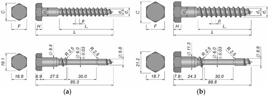
Figure 1.
A shear connector: (a) 10 mm screw; (b) 12 mm screw.
The tensile tests were conducted using an Instron 4483 machine (Instron, HighWycombe, Buckinghamshire, UK) and an Epsilon 3442-010M-025M-ST extensometer (Epsilon, Jackson, WY, USA) with a 10 mm gauge. The displacement rate was kept constant (0.05 mm/s).
2.4. Toothed Plates
Toothed-plate connectors (C2-50/M10G, C2-50/M12G or C11-50/M12) were used to reinforce the aluminium-timber screwed connections investigated in this paper.
A toothed plate (type C2, Bulldog) is a single-sided connector made from a circular plate. Its edges are cut and bent over to form triangular teeth projecting from one face at 90° to the face (see Figure 2a). Around the screw hole, there is a flange projecting from the same face as the teeth. The dimensions of the toothed plates used in this study are presented in Table 6. They were made from cold rolled uncoated low carbon narrow strips of HC340LA steel (high yield strength steel for cold forming) [39]. The toothed plates were hot dip galvanised (≥45 μm) to protect them from corrosion.
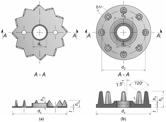
Figure 2.
Toothed-plate connectors: (a) type C2, Bulldog; (b) C11, Geka.
Table 6.
Dimensions of C2 (Bulldog) connectors 1,2 [41].
A toothed-plate connector (type C11-50/M12, Geka) is a single-sided connector made from a round plate with spikes on one side of the plate (see Figure 2b). The spikes are equidistant and are arranged in one circle. The toothed plate has a bolt-hole through its centre with a flange around the bolt-hole projecting from the same face as the spikes. The dimensions of the toothed plates used in this study are presented in Table 7. They were made of malleable cast iron EN-GJMB-350-10 (PN-JM 1130) according to EN 1562 [40] and galvanised (Fe/Zn12/C) to protect them from corrosion.
Table 7.
Dimensions of C11 (Geka) connectors 1 (connector type: C11-50/M12) [41].
2.5. Push-Out Tests
The tests were carried out on twenty models using an Instron 8505 Plus machine (In-stron, High Wycombe, Buckinghamshire, UK). Each experimental model consisted of two timber slabs made of LVL and a beam made of the AW-6060 T6 aluminium alloy (see Figure 3). The LVL slabs were connected with the aluminium beams using four variants of connections. In the first variant, eight hexagon head wood screws (10 × 80 mm2) without reinforcing toothed plates were used (specimen R10.1–R10.4). In the second variant, eight hexagon head wood screws (10 × 80 mm2) with reinforcing toothed plates (C2-50/M10G, Bulldog) were used (specimens 10.1–10.4). In the third variant, eight hexagon head wood screws (12 × 80 mm2) without reinforcing toothed plates were used (specimen R12.1–R12.4). In the four variant, eight hexagon head wood screws (12 × 80 mm2) with reinforcing toothed plates (C2-50/M12G, Bulldog) were used (specimens 12.1–12.4). In the fifth variant, eight hexagon head wood screws (12 × 80 mm2) with reinforcing toothed plates (C11-50/M12, Geka) were used (specimens 12.5–12.8).
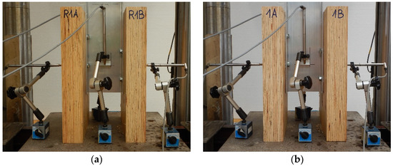
Figure 3.
The tested specimens: (a) without reinforcing toothed plates; (b) with reinforcing toothed plates.
The holes in the aluminium beams had the same diameter as the screws to reduce the slip between the aluminium beams and the LVL slabs. The pre-drilling diameter in LVL was 7 mm for the 10 mm screw and 8 mm for the 12 mm screw. Pre-drilling started the course of the screw and created pilot holes. Furthermore, the installation of the hexagon head wood screws required less effort. In each specimen, screws were inserted in the face withdrawal direction using a torque wrench (Sandvik Belzer, IZO-I-100, 10–100 Nm). The tread-grain angle was 90°. The torque level was measured during the insertion of the screws using a torque wrench and recorded at the end of the insertion process (35 Nm for 10 mm screw, 50 Nm for 12 mm screw). The toothed plates were pressed into LVL using a hydraulic press and a compressive force equal to 35 kN. The spaces between the screws were 50 mm in the transverse direction and 60 mm in the longitudinal direction. The staggered spacing was used because of the dimensions of the toothed plates. The loading direction was parallel to the LVL grain. Linear variable differential transformers (LVDTs) were used to measure the longitudinal slip between the LVL slabs and the aluminium beam, and the horizontal move of the sample (see Figure 4, Figure 5 and Figure 6).
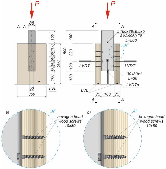
Figure 4.
The location of the LVDTs on the specimen without reinforcing toothed plates: (a) screws 10 × 80; (b) screws 12 × 80.
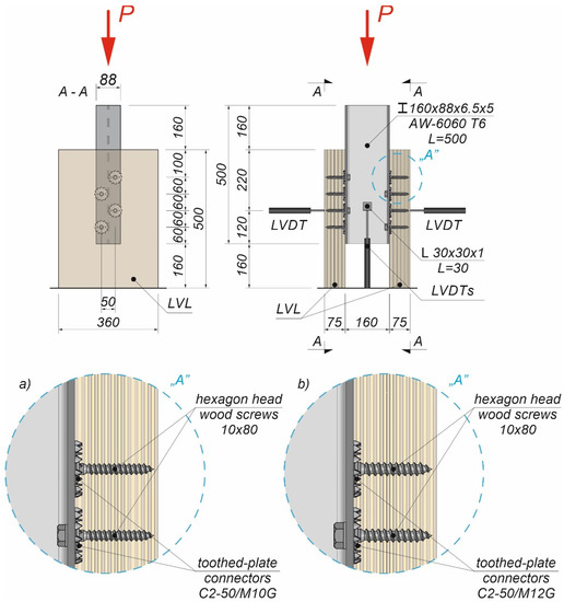
Figure 5.
The location of the LVDTs on the specimen with reinforcing toothed plates: (a) screws 10 × 80 and toothed-plate connectors (type C2-50/M10G); (b) screws 12 × 80 and toothed-plate connectors (type C2-50/M12G, Bulldog).
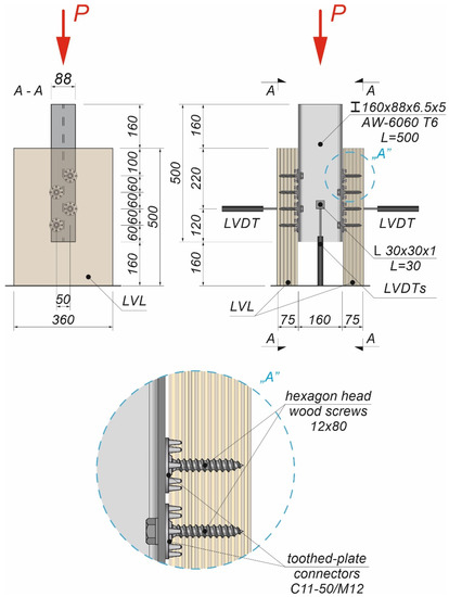
Figure 6.
The location of the LVDTs on the specimen with reinforcing toothed plates—screws 12 × 80 and toothed-plate connectors (type C11-50/M12, Geka).
The push-out tests were performed in line with [44]. In the first part of the test, a load control regime was applied to achieve a regular shape of the load–slip curve and to determine the connection slip modulus for a shear force equal to 40% of Fmax. In the second part of the test, a constant rate of displacement was used to evaluate the behaviour of the connection once the ultimate load had been achieved. The shear force was first increased from 0 to 40% of Fest over two minutes, and it remained at this level for the next 30 seconds. Afterwards the load was reduced from 40% to 10% of Fest and kept at this level for additional 30 seconds. Subsequently, the load was increased from 10% to 70% of Fest. Up to that point, the push-out tests were performed using a load control regime, and from then on—using a displacement control regime (the piston velocity was 5.0 mm/min). The ultimate load Fest = 130.0 kN was calculated based on Equation (8.10e) from Eurocode 5 [45]. The value of Fest was modified during the tests taking into account the previous results. The loading procedure was also redefined.
3. Results and Discussion
3.1. The Results of the Tensile Tests of the Steel Used in the Screws
The tensile strength of the steel used in the screws was 553.9 ± 23.6 MPa (4.3%) [46]. The measurement error for the tensile strength of the steel used in the screws was determined using Student’s t-distribution with 7 degrees of freedom and a confidence level of 95%.
3.2. The Results of the Push-Out Tests
The results of the push-out tests are presented in Figure 7, Figure 8 and Figure 9 and in Table 8, Table 9, Table 10, Table 11 and Table 12. The symbols used in Table 8, Table 9, Table 10, Table 11 and Table 12 are as follows: Pult, ultimate load per one connector; sult, slip corresponding to Pult; k0.4 and k0.6, slip moduli per one connector. The measurement errors presented in Table 8, Table 9, Table 10, Table 11 and Table 12 were determined using Student’s t-distribution with 3 degrees of freedom and a confidence level of 95%.
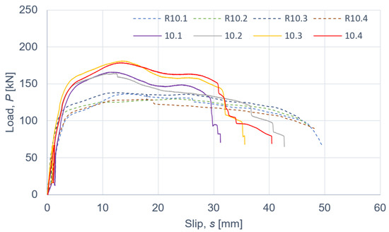
Figure 7.
The load–slip curves from the push-out tests of the shear connections with 10 mm screws and with toothed-plate connectors (type C2-50/M10G, Bulldog) in specimens 10.1–10.4 or without toothed-plate connectors in specimens R10.1-R10.4.
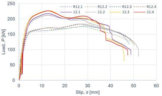
Figure 8.
The load–slip curves from the push-out tests of the shear connections with 12 mm screws and with toothed-plate connectors (type C2-50/M12G, Bulldog) in specimens 12.1–12.4 or without toothed-plate connectors in specimens R12.1-R12.4.
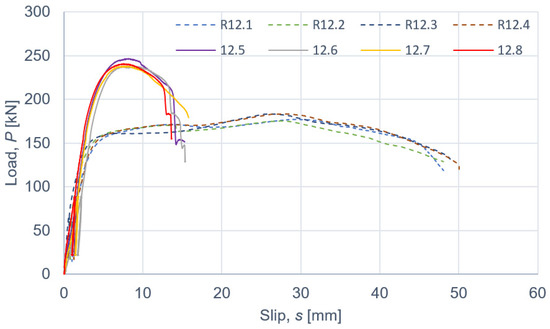
Figure 9.
The load–slip curves from the push-out tests of the shear connections with 12 mm screws and with toothed-plate connectors (type C11-50/M12, Geka) in specimens 12.5–12.8 or without toothed-plate connectors in specimens R12.1-R12.4.
Table 8.
The results of the push-out tests of the shear connections with 10 mm screws and without toothed-plate connectors (per one connector).
Table 9.
The results of the push-out tests of the shear connections with 10 mm screws and with toothed-plate connectors (type C2-50/M10G, Bulldog) (per one connector).
Table 10.
The results of the push-out tests of the shear connections with 12 mm screws and without toothed-plate connectors (per one connector).
Table 11.
The results of the push-out tests of the shear connections with 12 mm screws and with toothed-plate connectors (type C2-50/M12G, Bulldog) (per one connector).
Table 12.
The results of the push-out tests of the shear connections with 12 mm screws and with toothed-plate connectors (type C11-50/M12, Geka) (per one connector).
Taking into account the results of the specimens without the reinforcing toothed plates and comparing them with the mean ultimate load and the mean slip modulus of the specimens with the reinforcing toothed plates, the below conclusions were drawn.
The use of toothed-plate connectors in aluminium-timber composite connections can enhance their load-carrying capacity. An enhancement of 28.7% (for 10 mm screws and C2-50/M10G toothed-plate connectors), 23.8% (for 12 mm screws and C2-50/M12G toothed-plate connectors) or 35.0% (for 12 mm screws and C11-50/M12 toothed-plate connectors) was achieved in the respective screwed connections. Upon comparing the slip moduli of the tested connections, it was observed that the use of toothed plate connectors was ineffective in improving the stiffness of the aluminium-timber composite connections.
According to Eurocode 4 [47], a connection is ductile if its characteristic slip capacity is at least 6 mm. All the tested connections had the characteristic slip capacity exceeding 6 mm. However, the screwed connections with the C11-50/M12 toothed-plate connectors (Geka) had a brittle mode of failure—the unthreaded part of the screw was sheared. The screwed connections with the C2-50/M12G toothed-plate connectors (Bulldog) were more ductile than the screwed connections with the C11-50/M12 toothed-plate connectors (Geka) (compare Figure 8 and Figure 9). There was a single shear plane between the toothed-plate connectors and the aluminium beam flange. The stiffness of the Geka toothed-plate connector is higher than the stiffness of the Bulldog toothed-plate connector because the flange height of the former (6 mm) is 1.5 times higher than the flange height of the latter (4 mm), and the flange thickness of the former (2.25 mm) is 2.25 times higher than the thickness of the latter (1 mm). Furthermore, the thickness of the former (3 mm) is 3 times higher than the thickness of the latter (1 mm). In the case of the screwed connections with the C11-50/M12 toothed-plate connectors (Geka), the screws were sheared, whereas in the case of the screwed connections with the C2-50/M12G toothed-plate connectors (Bulldog), the toothed-plate connectors were torn.
The load-carrying capacity of the screwed connections with the C2-50/M12G toothed-plate connectors (Bulldog) (27.6 kN) was 1.09 times lower than the load-carrying capacity of the screwed connections with the C11-50/M12 toothed-plate connectors (Geka) (30.1 kN).
The tested screwed connections with or without Bulldog toothed-plate connectors (C2-50/M10G, C2-50/M12G) showed one distinctive mode of failure presented in Figure 10, Figure 11, Figure 12 and Figure 13. The authors observed the formation of two plastic hinges within the screw, the crushing of LVL, hole ovalisation in the flange of the aluminium alloy beam, and hole ovalisation in the toothed plate or its tearing. In the specimens where the teeth were strongly connected with the LVL and did not allow for the movement of the toothed plates, the toothed plates were torn (see Figure 11). Some of the screws were sheared near the end of the tests. In Figure 10, Figure 11, Figure 12, Figure 13 and Figure 14, the symbol ly was used to present the mean length of the yielded zone in the aluminium flange (measured at the end of the tests). The yielded zone was caused by the bearing of the screw to the hole wall.
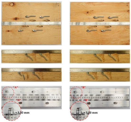
Figure 10.
The mode of failure of the aluminium-timber connection with the 10 mm screws and without the reinforcing toothed plates.
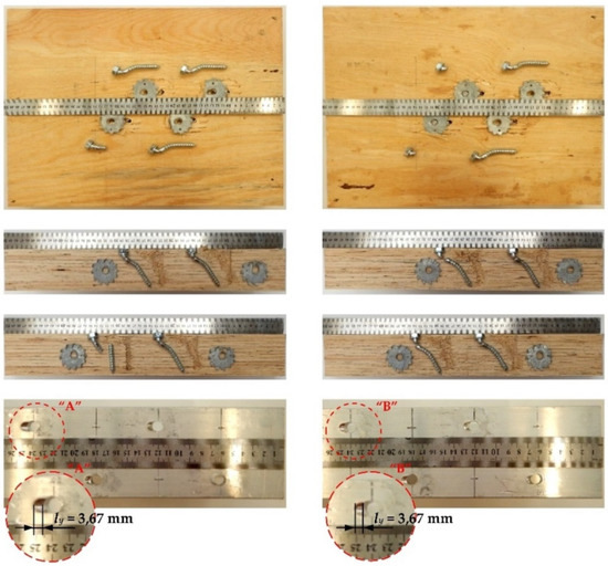
Figure 11.
The mode of failure of the aluminium-timber connection with the 10 mm screws and the reinforcing toothed plates (C2-50/M10G, Bulldog).
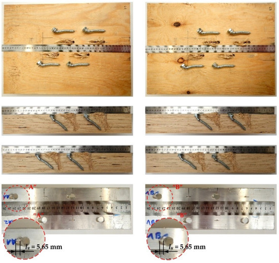
Figure 12.
The mode of failure of the aluminium-timber connection with the 12 mm screws and without the reinforcing toothed plates.
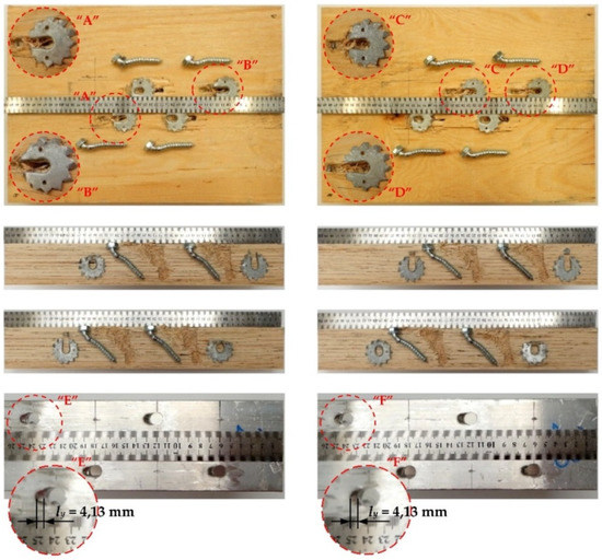
Figure 13.
The mode of failure of the aluminium-timber connection with the 12 mm screws and the reinforcing toothed plates (C2-50/M12G, Bulldog).
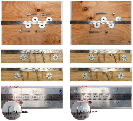
Figure 14.
The mode of failure of the aluminium-timber connection with the 12 mm screws and the reinforcing toothed plates (C11-50/M12, Geka).
The tested screwed connections with Geka toothed-plate connectors (C11-50/M12) showed one distinctive mode of failure presented in Figure 14. The screws were sheared and some of the plate teeth were broken. The authors also observed the crushing of LVL and the hole ovalisation in the flange of the aluminium alloy beam. In the case of Geka toothed-plate connectors, the mean length of the yielded zone in the aluminium flange was shorter than in the Bulldog toothed-plate connectors. The connections with the Geka toothed-plates had a lower slip corresponding to the ultimate load than the connections with the Bulldog toothed-plates.
The failure mode of the tested screwed connections with or without Bulldog toothed-plate connectors is taken into account in Equation (8.10e) presented in [45]:
where: Pv,Rk is the characteristic load-carrying capacity of the screw in a single shear (13.3 kN for the 9.43 mm screw and 17.5 kN for the 11.31 mm screw) calculated from Equation (1), fh,k is the characteristic embedment strength of the timber (40.8 MPa for the 9.43 mm screw and 40.0 MPa for the 11.31 mm screw) calculated from [45], t is the penetration depth (70.0 mm in this paper), My,Rk is the characteristic fastener yield moment (54 372 N·mm for the 9.43 mm screw and 87 226 N·mm for the 11.31 mm screw) calculated from [45], fu,k is the characteristic tensile strength of the screw (530.3 MPa—5%-quantile from the tensile tests), and Fax,Rk is the characteristic withdrawal capacity of the fastener (11,011 N for the 9.43 mm screw and 12 059 N for the 11.31 mm screw) calculated from [45].
The mean values of the screw shank diameters (9.43 mm for the 10 mm screw and 11.31 mm for the 12 mm screw) from Table 3 and Table 4 were used in the calculations based on Equations (1)–(4).
The characteristic load-carrying capacity of the 9.43 mm screw calculated from Equation (1) (13.3 kN) was 1.29 times lower than the ultimate load per one screw in the screwed connection without the reinforcing toothed plate (17.1 kN) and 1.62 times lower than the ultimate load per one screw in the reinforced screwed connection (21.5 kN). The characteristic load-carrying capacity of the 11.31 mm screw calculated from Equation (1) (17.5 kN) was 1.22 times lower than the ultimate load per one screw in the screwed connection without the reinforcing toothed plate (21.4 kN) and 1.58 times lower than the ultimate load per one screw in the reinforced screwed connection (27.6 kN). The model presented in Eurocode 5 does not take into account the reinforcing toothed plate. For this reason, the values obtained from Equation (1) are similar to the values obtained in the tests of the screwed connections without the reinforcing toothed plates, and lower than the ones from the tests with the reinforcing toothed plates.
The failure mode of the tested screwed connections with Geka toothed-plate connectors (C11-50/M12), i.e., the shearing of the unthreaded part of the screw, is taken into account in the equation presented in Table 3.4 in [48]:
where: Pv,Rk is the characteristic load-carrying capacity of the screw in a single shear (26.7 kN for the 11.31 mm screw) calculated from Equation (2), αv is the coefficient from [48] (0.6), A is the gross cross-section area of the connector, γM2 is the partial safety factor, fub is the ultimate strength of the steel used in the shear connector.
The characteristic load-carrying capacity of the 11.31 mm screw calculated from Equation (2) (26.7 kN) was 1.03 times lower than the ultimate load per one screw in the screwed connection without the reinforcing toothed plate (27.6 kN) and 1.13 times lower than the ultimate load per one screw in the reinforced screwed connection (30.1 kN). The model presented in Eurocode 5 does not take into account the reinforcing toothed plate. For this reason, the values obtained from Equation (2) are similar to the values obtained in the tests of the screwed connections without the reinforcing toothed plates, and lower than the values from the tests with the reinforcing toothed plates.
Hassanieh et al. [49] presented the formulae that can characterise the load-carrying capacity of the steel-timber screwed connection (per one connector).
where: Pult is the ultimate load per one connector (14.5 kN for the 9.43 mm screw and 20.0 kN for the 11.31 mm screw) calculated from Equation (2), d is the screw diameter.
Steel-timber composite structures are similar to aluminium-timber composite ones. The characteristic load-carrying capacity of the 9.43 mm screw calculated from Equation (3) (14.5 kN) was 1.18 times lower than the ultimate load per one screw in the screwed connection without the reinforcing toothed plate (17.1 kN) and 1.48 times lower than the ultimate load per one screw in the reinforced screwed connection (21.5 kN). The characteristic load-carrying capacity of the 11.31 mm screw calculated from Equation (3) (20.0 kN) was 1.07 times higher than the ultimate load per one screw in the screwed connection without the reinforcing toothed plate (21.4 kN) and 1.38 times lower than the ultimate load per one screw in the reinforced screwed connection (27.6 kN). The model presented by Hassanieh et al. [49] does not take into account the reinforcing toothed plate, neither does the model presented in Eurocode 5. The results of the tests presented in this article show that reinforcing LVL by toothed-plate connectors is effective in increasing the load-carrying capacity of screwed connections. An enhancement of 23.8%, 28.7%, or 35.0% was achieved in the screwed connections with 10 or 12 mm screws, respectively. For this reason, the authors of this paper suggested Equation (3) be modified by adding a coefficient of 1.24, taking into account the lowest value of the enhancements obtained from the tests, to characterise the load-carrying capacity of the aluminium-timber screwed connection reinforced with toothed-plate connectors:
The characteristic load-carrying capacity of the 9.43 mm screw calculated from Equation (4) (18.0 kN) was 1.19 times lower than the ultimate load per one screw in the reinforced screwed connection (21.5 kN). The characteristic load-carrying capacity of the 11.31 mm screw calculated from Equation (4) (24.9 kN) was 1.11 times lower than the ultimate load per one screw in the screwed connection reinforced by the C2-50/M12G toothed plates (27.6 kN) and 1.21 times lower than the ultimate load per one screw in the screwed connection reinforced by the C11-50/M12 toothed plates (30.1 kN).
In this paper, toothed plates were used as reinforcement. However, LVL can also be reinforced using other steel elements. For example, Hassanieh et al. [49] used reinforcing nail plates. They compared the load-carrying capacity and the stiffness of steel-timber screwed connections with and without nail plates. Hassanieh et al. [49] showed that the use of nail plates increased the stiffness of the connection, e.g., by 22% for 16 mm screws. What is more, reinforcing the LVL slab by nail plates enhanced the load-carrying capacity of the connection, e.g., by 19% for 16 mm screws. They also observed that nail plates had a minor influence on the load-carrying capacity of the steel-timber composite connections loaded in the direction perpendicular to the grain. The influence of the toothed plates (C2-50/M10G, C2-50/M12G, C11-50/M12) used in the tests presented in this article on the load-carrying capacity of the aluminium-timber screwed connections was similar to the impact of the nail plates used by Hassanieh et al. [49] on the load-carrying capacity of the steel-timber screwed connections.
4. Conclusions
In this paper, the load-carrying capacity, stiffness, load-slip response, failure modes and ductility of aluminium-timber screwed connections with and without toothed plates were investigated. Push-out tests with symmetrical configurations were conducted.
Based on the results of the tests, the following conclusions can be drawn. Aluminium-timber screwed connections can be reinforced using toothed plates. Reinforcing LVL by toothed-plate connectors can enhance the load-carrying capacity of screwed connections. Enhancements of 28.7% (for 10 mm screws and C2-50/M10G toothed-plate connectors), 23.8% (for 12 mm screws and C2-50/M12G toothed-plate connectors) or 35.0% (for 12 mm screws and C11-50/M12 toothed-plate connectors) were achieved in the screwed connections. However, the use of toothed plate connectors was found to be ineffective in improving the stiffness of aluminium-timber composite connections.
The authors demonstrated that the existing design rules did not take into account the strengthening effect of toothed plates on the connection load-carrying capacity, and they suggested the use of a coefficient equal to 1.24 to better characterise the load-carrying capacity of aluminium-timber screwed connections reinforced with toothed-plate connectors.
Furthermore, the screwed connections reinforced with toothed plates may be used in aluminium-timber composite beams. The tests presented in this paper make it possible to determine the number of connectors necessary to achieve the required level of composite action. Last, but not least, the obtained load-slip curves for the analysed connections can be used in numerical models of aluminium-timber composite beams, to model connection behaviour using spring elements. This method of connection modelling was used, e.g., in [25,27,30,50,51].
Author Contributions
Conceptualization, M.C. and Ł.P.; methodology, M.C. and Ł.P.; investigation, M.C. and Ł.P.; specimens preparation, M.C. and Ł.P.; writing—original draft preparation, M.C. and Ł.P.; writing—review and editing, M.C. and Ł.P.; visualization, M.C. and Ł.P. All authors have read and agreed to the published version of the manuscript.
Funding
This research was funded by the Polish Ministry of Science and Higher Education under grants 0412/SBAD/0044, 0412/SBAD/0046 and 0412/SBAD/0050.
Institutional Review Board Statement
Not applicable.
Informed Consent Statement
Not applicable.
Data Availability Statement
All data contained within the article.
Acknowledgments
The authors wish to thank STEICO company for the LVL panels.
Conflicts of Interest
The authors declare no conflict of interest.
References
- Bergman, R.; Puettmann, M.; Taylor, A.; Skog, K.E. The carbon impacts of wood products. For. Prod. J. 2014, 64, 47. [Google Scholar] [CrossRef]
- Porteous, J.; Kermani, A. Structural Timber Design to Eurocode 5, 2nd ed.; Wiley-Blackwell: Chichester, UK, 2013. [Google Scholar]
- Mirski, R.; Dziurka, D.; Chuda-Kowalska, M.; Wieruszewski, M.; Kawalerczyk, J.; Trociński, A. The usefulness of pine timber (Pinus sylvestris L.) for the production of structural elements. Part I: Evaluation of the quality of the pine timber in the bending test. Materials 2020, 13, 3957. [Google Scholar] [CrossRef]
- Witomski, P.; Krajewski, A.; Kozakiewicz, P. Selected mechanical properties of Scots pine wood from antique churches of Central Poland. Eur. J. Wood Wood Prod. 2014, 72, 293–296. [Google Scholar] [CrossRef][Green Version]
- Brandner, R.; Ringhofer, A.; Grabner, M. Probabilistic models for the withdrawal behavior of single self-tapping screws in the narrow face of cross laminated timber (CLT). Eur. J. Wood Wood Prod. 2018, 76, 13–30. [Google Scholar] [CrossRef]
- Brandner, R.; Ringhofer, A.; Reichinger, T. Performance of axially-loaded self-tapping screws in hardwood: Properties and design. Eng. Struct. 2019, 188, 677–699. [Google Scholar] [CrossRef]
- Bakalarz, M.; Kossakowski, P.; Tworzewski, P. Strengthening of bent LVL beams with near-surface mounted (NSM) FRP reinforcement. Materials 2020, 13, 2350. [Google Scholar] [CrossRef]
- Wdowiak-Postulak, A.; Świt, G. Behavior of glulam beams strengthened in bending with BFRP fabrics. Civ. Environ. Eng. Rep. 2021, 2, 16. [Google Scholar] [CrossRef]
- Kula, K.; Socha, T. Renovation and strengthening of wooden beams with CFRP bands including the rheological effects. Civ. Environ. Eng. Rep. 2016, 22, 93–102. [Google Scholar] [CrossRef][Green Version]
- Wróblewski, T.; Berczyński, S.; Abramowicz, M. Estimation of the parameters of the discrete model of a steel-concrete composite beam. Arch. Civ. Mech. Eng. 2013, 13, 209–219. [Google Scholar] [CrossRef]
- Kyvelou, P.; Gardner, L.; Nethercot, D.A. Design of composite cold-formed steel flooring systems. Structures 2017, 12, 242–252. [Google Scholar] [CrossRef]
- Chybiński, M.; Polus, Ł.; Szwabiński, W.; Niewiem, P. FE analysis of steel-timber composite beams. In Proceedings of the Computational Technologies in Engineering (TKI’2018): 15th Conference on Computational Technologies in Engineering, Jora Wielka, Poland, 16–19 October 2018; Baranowski, P., Kędzierski, P., Szurgott, A., Eds.; AIP Publishing: Melville, NY, USA, 2019; pp. 020061-1–020061-6. [Google Scholar] [CrossRef]
- Łukaszewska, E.; Fragiacomo, M.; Johnsson, H. Laboratory tests and numerical analyses of prefabricated timber-concrete composite floors. J. Struct. Eng. 2010, 136, 46–55. [Google Scholar] [CrossRef]
- Szumigała, M.; Szumigała, E.; Polus, Ł. Laboratory tests of new connectors for timber-concrete composite structures. Eng. Trans. 2018, 66, 161–173. [Google Scholar]
- Szumigała, M.; Chybiński, M.; Polus, Ł. Preliminary analysis of the aluminium-timber composite beams. Civ. Environ. Eng. Rep. 2017, 27, 131–141. [Google Scholar]
- Szumigała, M.; Chybiński, M.; Polus, Ł. Stiffness of composite beams with full shear connection. IOP Conf. Ser. Mater. Sci. Eng. 2019, 471, 052083. [Google Scholar] [CrossRef]
- Furtak, K.; Rodacki, K. Experimental investigations of load-bearing capacity of composite timber-glass I-beams. Arch. Civ. Mech. Eng. 2018, 18, 956–964. [Google Scholar] [CrossRef]
- Kozłowski, M.; Kadela, M.; Hulimka, J. Numerical investigation of structural behavior of timber-glass composite beams. Procedia Eng. 2016, 161, 78–89. [Google Scholar] [CrossRef]
- Bedon, C.; Sciomenta, M.; Fragiacomo, M. Correlation approach for the Push-Out and full-size bending short-term performances of timber-to-timber slabs with Self-Tapping Screws. Eng. Struct. 2021, 238, 112232. [Google Scholar] [CrossRef]
- Łukaszewska, E.; Johnsson, H.; Fragiacomo, M. Performance of connections for prefabricated timber-concrete composite floors. Mater. Struct. 2008, 41, 1533–1550. [Google Scholar] [CrossRef]
- Hassanieh, A.; Valipour, H.R.; Bradford, M.A. Experimental and numerical study of steel-timber composite (STC) beams. J. Constr. Steel Res. 2016, 122, 367–378. [Google Scholar] [CrossRef]
- Vella, N.; Gardner, L.; Buhagiar, S. Analytical modelling of cold-formed steel-to-timber connections with inclined screws. Eng. Struct. 2021, 249, 113187. [Google Scholar] [CrossRef]
- Saleh, S.M.; Jasim, N.A. Structural behavior of timber aluminum composite beams under static loads. Int. J. Eng. Res. Technol. 2014, 3, 1166–1173. [Google Scholar]
- Saleh, S.M.; Jasim, N.A. Structural behavior of timber aluminum composite beams under impact loads. Int. J. Sci. Eng. Res. 2014, 5, 865–873. [Google Scholar]
- Chybiński, M.; Polus, Ł. Theoretical, experimental and numerical study of aluminium-timber composite beams with screwed connections. Constr. Build. Mater. 2019, 226, 317–330. [Google Scholar] [CrossRef]
- Szumigała, M.; Chybiński, M.; Polus, Ł. Composite beams with aluminium girders—A review. In Proceedings of the Modern Trends in Research on Steel, Aluminium and Composite STRUCTURES: XIV International Conference on Metal Structures (ICMS2021), Poznan, Poland, 16–18 June 2021; Giżejowski, M.A., Ed.; Routledge: Leiden, The Netherlands, 2021; pp. 249–255. [Google Scholar] [CrossRef]
- Chybiński, M.; Polus, Ł. Experimental and numerical investigations of aluminium-timber composite beams with bolted connections. Structures 2021, 34, 1942–1960. [Google Scholar] [CrossRef]
- Yeoh, D.; Fragiacomo, M.; Deam, B. Experimental behaviour of LVL-concrete composite floor beams at strength limit state. Eng. Struct. 2011, 33, 2697–2707. [Google Scholar] [CrossRef]
- Nie, Y.; Valipour, H.R. Experimental and numerical study of long-term behaviour of timber-timber composite (TTC) connections. Constr. Build. Mater. 2021, 304, 124672. [Google Scholar] [CrossRef]
- Chiniforush, A.A.; Valipour, H.R.; Ataei, A. Timber-timber composite (TTC) connections and beams: An experimental and numerical study. Constr. Build. Mater. 2021, 303, 124493. [Google Scholar] [CrossRef]
- Ringhofer, A. Axially Loaded Self-Tapping Screws in Solid Timber and Laminated Timber Products; TU Graz: Graz, Austria, 2017. [Google Scholar]
- Ringhofer, A.; Brandner, R.; Schickhofer, G. Withdrawal resistance of self-tapping screws in unidirectional and orthogonal layered timber products. Mater. Struct. 2015, 48, 1435–1447. [Google Scholar] [CrossRef]
- Loss, C.; Piazza, M.; Zandonini, R. Connections for steel-timber hybrid prefabricated buildings. Part I: Experimental tests. Constr. Build. Mater. 2016, 122, 781–795. [Google Scholar] [CrossRef]
- Chybiński, M.; Polus, Ł. Experimental and numerical investigations of laminated veneer lumber panels. Arch. Civ. Eng. 2021, 67, 351–372. [Google Scholar] [CrossRef]
- Komorowski, M. Manual of Design and Build in the STEICO System, Basic Information, Building Physics, Guidelines; Forestor Communication: Warsaw, Poland, 2017. (In Polish) [Google Scholar]
- European Committee for Standardization. EN ISO 6892-1, Metallic Materials—Tensile Testing—Part 1: Method of Test at Room Temperature; European Committee for Standardization: Brussels, Belgium, 2016. [Google Scholar]
- Chybiński, M.; Polus, Ł.; Ratajczak, M.; Sielicki, P.W. The evaluation of the fracture surface in the AW-6060 T6 aluminium alloy under a wide range of loads. Metals 2019, 9, 324. [Google Scholar] [CrossRef]
- German Institute for Standardization. DIN 571:2016-12, Hexagon Head Wood Screws; German Institute for Standardization: Berlin, Germany, 2016. [Google Scholar]
- European Committee for Standardization. EN 10268, Cold Rolled Steel Flat Products with High Yield Strength for Cold Forming, Technical Delivery Conditions; European Committee for Standardization: Brussels, Belgium, 2006. [Google Scholar]
- European Committee for Standardization. EN 1562 Founding—Malleable Cast Irons; European Committee for Standardization: Brussels, Belgium, 2019. [Google Scholar]
- European Committee for Standardization. EN 912, Timber Fasteners, Specifications for Connectors for Timbers; European Committee for Standardization: Brussels, Belgium, 2011. [Google Scholar]
- European Committee for Standardization. EN 10131, Cold Rolled Uncoated and Zinc or Zinc-Nickel Electrolytically Coated Low Carbon and High Yield Strength Steel Flat Products for Cold Forming—Tolerances on Dimensions and Shape; European Committee for Standardization: Brussels, Belgium, 2006. [Google Scholar]
- European Committee for Standardization. EN 10140, Cold Rolled Narrow Steel Strip—Tolerances on Dimensions and Shape; European Committee for Standardization: Brussels, Belgium, 2006. [Google Scholar]
- European Committee for Standardization. EN 26891, Timber Structures—Joints Made with Mechanical Fasteners—General Principles for the Determination of Strength and Deformation Characteristics; European Committee for Standardization: Brussels, Belgium, 1991. [Google Scholar]
- European Committee for Standardization. EN 1995-1-1, Eurocode 5: Design of Timber Structures—Part 1-1: General—Common Rules and Rules for Buildings; European Committee for Standardization: Brussels, Belgium, 2004. [Google Scholar]
- Research Report: 100/21/BB.903.0287.05; The Łukasiewicz Research Network; Metal Forming Institute: Poznań, Poland, 2021.
- Johnson, R.P. Designers’ Guide to Eurocode 4: Design of Composite Steel and Concrete Structures, EN 1994-1-1; ICE Publishing: London, UK, 2012. [Google Scholar]
- European Committee for Standardization. EN 1993-1-8, Eurocode 3: Design of Steel Structures—Part 1-8: Design of Joints; European Committee for Standardization: Brussels, Belgium, 2005. [Google Scholar]
- Hassanieh, A.; Valipour, H.R.; Bradford, M.A. Experimental and analytical behaviour of steel-timber composite connections. Constr. Build. Mater. 2016, 118, 63–75. [Google Scholar] [CrossRef]
- Wróblewski, T.; Pełka-Sawenko, A.; Abramowicz, M.; Berczyński, S. Parameter identification of steel-concrete composite beams by finite element method. Diagnostyka 2013, 14, 43–46. [Google Scholar]
- Polus, Ł.; Szumigała, M. Finite element modelling of the connection for timber-concrete composite beams. IOP Conf. Ser. Mater. Sci. Eng. 2019, 471, 052081. [Google Scholar] [CrossRef]


Publisher’s Note: MDPI stays neutral with regard to jurisdictional claims in published maps and institutional affiliations. |
© 2021 by the authors. Licensee MDPI, Basel, Switzerland. This article is an open access article distributed under the terms and conditions of the Creative Commons Attribution (CC BY) license (https://creativecommons.org/licenses/by/4.0/).