Article

Optimization of Machining Parameters for Milling Zirconia Ceramics by Polycrystalline Diamond Tool

1
College of Mechanical Engineering, North China University of Science and Technology, No. 21 Bohai Road, Caofeidian Xincheng, Tangshan 063210, China
2
Shanxi Limin Industrial Co. Ltd., Jinzhong 030812, China
3
Kama Automobile Company, No. 5888, Donghuan Road, Shouguang 262700, China
*
Authors to whom correspondence should be addressed.
Materials 2022, 15(1), 208; https://doi.org/10.3390/ma15010208
Submission received: 3 December 2021 / Revised: 20 December 2021 / Accepted: 22 December 2021 / Published: 28 December 2021

Abstract

:
Zirconia ceramics are widely used in many fields because of their excellent physical and mechanical properties. However, there are some challenges to machine zirconia ceramics with high processing efficiency. In order to optimize parameters for milling zirconia ceramics by polycrystalline diamond tool, finite element method was used to simulate machining process based on Johnson-Cook constitutive model. The effects of spindle speed, feed rate, radial and axial cutting depth on cutting force, tool flank wear and material removal rate were investigated. The results of the simulation experiment were analyzed and optimized by the response surface method. The optimal parameter combination was obtained when the spindle speed, feed rate, radial and axial cutting depth were 8000 r/min, 90.65 mm/min, 0.10 mm and 1.37 mm, respectively. Under these conditions, the cutting force was 234.81 N, the tool flank wear was 33.40 μm when the milling length was 60 mm and the material removal rate was 44.65 mm3/min.

1. Introduction

Zirconia ceramics are characterized by high toughness, high bending strength, high wear resistance, excellent heat insulation, well corrosion resistance and biocompatibility [1,2,3], which have been expansively used in many areas such as aerospace, precision machinery and biomedicine [4,5,6,7,8]. High-efficiency processing for zirconia ceramics has become a research hotspot. The milling of zirconia ceramics can obtain complex three-dimensional structures and surface quality equivalent to grinding, which can make up for the limitations of existing processing technology to a certain extent [9]. However, it is different to machine zirconia ceramics because of their high toughness, high bending strength, high wear resistance and excellent heat insulation which cause severe tool wear and tipping, low surface quality and machining efficiency [10]. Polycrystalline diamond (PCD) tool has the advantages of high hardness, good thermal conductivity, low friction coefficient and low thermal expansion coefficient, which is an ideal tool for milling zirconia ceramics [11,12]. In recent years, a lot of research about surface quality, tool wear and material removal rate has been done when zirconia ceramics are machined by PCD tool [13,14,15].
Eleonora et al. [16] investigated the effects of cutting parameters on surface quality and tool wear cutting parameters on high speed hard cutting with PCD tool. The results showed that the material was mainly removed by combining ductile-brittle phases, and the tool wear was largely produced by workpiece material sticked to the tool. Bian et al. [17] studied the relationship between cutting parameters and brittle-tough critical cutting thickness during milling zirconia ceramics by using PCD tool. It was found that the appropriate increasing axial depth of cut can prevent the brittleness damage from affecting the machined surface and increase the material removal rate with the stabilization of the surface roughness within a certain range. Rong et al. [18] considered the PCD tool with bigger particle size possesses longer tool life. The surface roughness was primarily affected by feed per tooth, which increased with the increase of feed per tooth teeth. Wan et al. [19] established a thermal-mechanical coupling simulation model of zirconia grinding to simulate the subsurface damage. Under the Thermal-mechanical coupling effect, simulation results were deviation of less than 6% compared with the experimental results. Li et al. [20] investigated the temperature distribution influenced by temperature dependent thermal properties and heat flux profile based on a heat transfer model. The results shown that the temperature had the greatest impact by cutting depth. Xue et al. [21] built a finite element model to analyze the influence of depth of cut on stress changes and crack distribution during cutting process of zirconia ceramics. The results showed that the simulation analysis was beneficial for the optimization of machining parameters. Deng et al. [22] simulated the process of diamond fly-cutting zirconia ceramics, and studied the influence of tool geometric parameters and cutting parameters on stress distribution, brittle-plastic transition depth, cutting force and chip morphology. Hence, numerical simulation could be used to reveal the processing mechanism of milling zirconia ceramics.
During the milling of zirconia ceramic, the processing parameters should be accurately controlled because of the brittle fracture of zirconia ceramics, especially when the workpiece material is thin. Meanwhile, maching is accompanied by severe tool wear and low machining efficiency. It is very important to optimize the milling parameters of zirconia ceramics. In this paper, a finite element simulation model of PCD tool milling zirconia ceramics based on Johnson-Cook constitutive model was established. The milling experiments were designed with the central composite design method, and the simulation data was analyzed by regression analysis. The response surface method was used to analyze the effect of cutting parameters on cutting force, tool flank wear and material removal rate. The optimized parameter combination was obtained for the cutting force, tool flank wear, and material removal. The specific experiments were performed to verify simulation results.

2. Simulation Details

2.1. Constitutive Model

The Johnson-Cook constitutive equation was used to establish the constitutive model of zirconia ceramics milled by PCD tool. The model reflected the coupling effects of strain hardening, strain rate strengthening, and thermal softening during the cutting process. The expression is as follows [23]:
σ ¯ = [ A + B ( ε ¯ ) n ] [ 1 + C ln ( ε ¯ ˙ / ε ¯ ˙ 0 ) ] [ 1 ( ( T T r ) / ( T m T r ) ) m ]
where, σ ¯ is equivalent flow stress (Mpa). A, B, C, n, m are the constants of the material under reference conditions, denoting yield stress (Mpa), strain hardening constant (Mpa), strengthening coefficient of strain rate, strain hardening coefficient and thermal softening coefficient, respectively. ε ¯ is equivalent plastic strain; ε ¯ ˙ is equivalent plastic strain rate, and ε ¯ ˙ 0 is reference strain rate. T, Tr and Tm are maximum temperature of material, room temperature and melting temperature, respectively, usually measured in °C.
Johnson-Cook constitutive model parameters for zirconia ceramics are shown in Table 1.

2.2. Three-Dimensional Finite Element Model

The physical properties of zirconia ceramics and PCD are shown in Table 2. The PCD tool is a second straight-tooth groove end mill with a diameter of 8 mm, helix angle and rake angle of 0°, and rear angle of 10°. The size of the zirconia ceramic is 100 × 30 × 20 mm3. The coefficient of friction is 0.3 incorporating a modified coulomb friction law with dry milling [24]. The zirconia ceramic and PCD are adopted an 8-node hexahedral element (C3D8RT) and 4-node tetrahedral unit (C3D4T), respectively. The milling schematic diagram is shown in Figure 1.
The material removal rate Q is determined by the distance of milling and axial and radial depth per unit time. The Q is calculated by the equation:
Q = v f α e α p
where, v f is feed rate of tool feed rate, mm/s. α e and α p are the radial and axial depth of milling, mm, respectively.
During zirconia ceramic milled by PCD tool, the large cutting force will intensify the friction between the tool and the workpiece contact surface leading to severe damage on the tool surface, especially flank face. The rake and flank angle of the PCD tool used in this research is 0° and 10°, respectively. The schematic illustration of tool wear is shown in Figure 2. EOD is the shape of the tool. After the tool wear, the shape of the tool is EBCD as shown in Figure 2a,b shows the A-direction view of the tool. VB is the average wear of the flank face. In order to simplify the measurement of tool wear, tool wear in this research was replaced by VB [25].
Response surface method was used to design the simulation experiment, which could obtain the influence of experiment parameter on results and its significance. Combined with engineering experience, four cutting parameters with five different levels of each were studied in the simulation experiment. The factors level of spindle speed (n), feed rate (vf), radial depth of cut (ae), and axial depth of cut (ap) are shown in Table 3. The cutting force (F), tool flank wear (VB) and material removal rate (Q) were as the response performance indicator.

3. Results and Discussion

3.1. Simulation Results

The simulation results of milling zirconia ceramics by PCD tool is shown in Figure 3. It can be seen that the stress mainly concentrated in the tip. For the simulation experiments, the simulation results of F, VB and Q under different n, vf, ae and ap with the milling length of 60 mm are shown in Table 4.

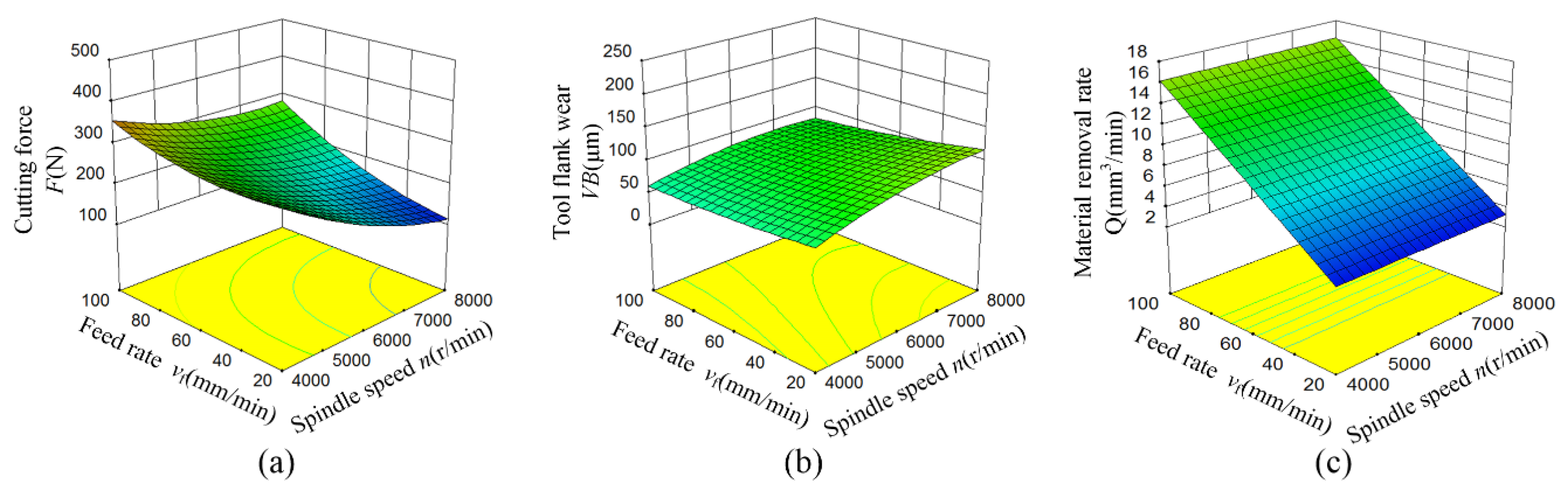
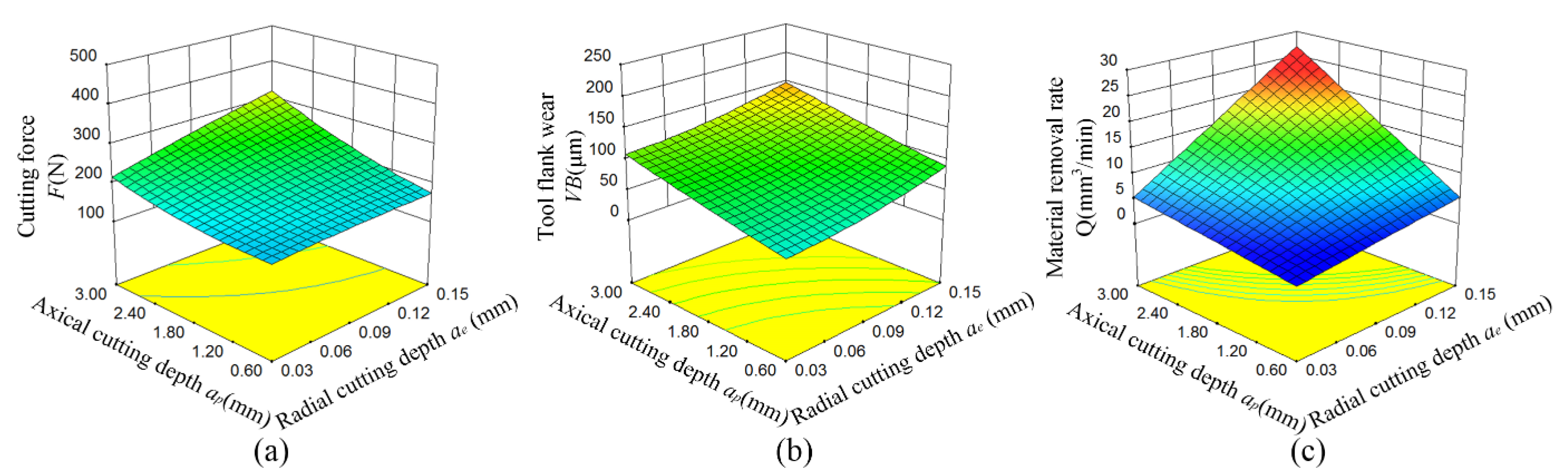
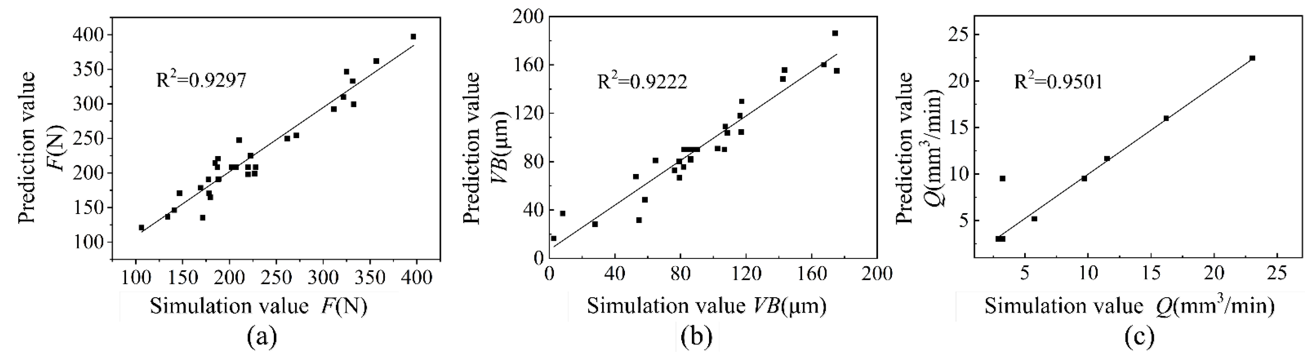
3.2. Response Surface Analysis

The influences of spindle speed and feed rate on cutting force, tool flank wear and material removal rate are shown in Figure 4. It can be seen that the cutting force decreases significantly with the increase of spindle speed as shown in Figure 4a. The reason for this is that the increase of spindle speed causing the temperature of the processing area rise which reduces the strength and hardness of zirconia ceramics. However, the influences of spindle speed on tool flank wear and material removal rate are not obvious as shown in Figure 4b,c. The cutting force and material removal rate are increased with the increase of feed rate, especially material removal rate. Increasing the feed rate could increase the scan area of the tool in unit time results in an increase in material removal rate. The interaction between spindle speed and feed rate has the most significant impact on the cutting force, followed by tool flank wear, but no significant impact on the material removal rate.
The influences of radial and axial depth of cut on the cutting force, tool flank wear and material removal rate are shown in Figure 5. Radial depth of cut increase caused a slight increase of cutting force and tool flank wear, mainly because the cutting distance becomes longer and the cutting amount increases when the axial depth of the tool contact remains unchanged. The contact area between the tool and the workpiece increased with the increase of axial depth of cut [26]. Therefore, the cutting force and tool flank wear increased more than increasing the radial depth of cut as shown in Figure 5a–c shows that the material removal rate increased significantly regardless of whether the radial or axial depth of cut increased. The interaction between radial and axial depth of cut has a significant impact on the material removal rate, followed by cutting force and tool flank wear.

3.3. Parameter Optimization

Multiple regression fitting was used to analyze the influence of n, vf, ae and ap on F, VB and Q. The second-order regression prediction models of F (N), VB (mm) and Q (mm3/min) are shown as follow:
F = 906.66 0.13 n 4.31 v f 2395.69 a e 137.59 a p + 6.71 × 10 6 n 2 + 0.02 v f 2 4187.85 a e 2 + 38.41 a p 2 + 3.48 × 10 4 n v f + 0.28 n a e 0.01 n a p + 0.92 v f a e + 0.84 v f a p + 1300.73 a e a p
V B = 224.65 + 0.12 n 0.48 v f 1751.28 a e 57.01 a p 1.03 × 10 5 n 2 + 0.01 v f 2 + 8481.71 a e 2 + 4.28 a p 2 2.69 × 10 4 n v f + 0.09 n a e + 0.02 n a p + 5.851 v f a e 0.13 v f a p + 1.60 a e a p
Q = 3.5 × 10 5 38.88 n 3888 v f 2.59 × 10 6 a e 1.3 × 10 5 a p + 0.32 n v f + 216 n a e + 10.8 n a p + 21600 v f a e + 1080 v f a p + 7.2 × 10 5 a e a p
Residual error was used to estimate whether the regression model is reasonable. Figure 6 shows the relation between predicted and simulated values of F, VB and Q. It can be seen that all sample points are close to a straight line, and there are no out-of-range sample points. The correlation coefficient (R2) of F, VB and Q is 0.9297, 0.9222 and 0.9501, respectively, which indicates that the second-order regression prediction models have less error and higher reliability [27,28].
In order to further analyze the experimental factors on F, VB and Q, the regression prediction models were analyzed by variance analysis. The results are shown in Table 5.
The F-value in Table 5 represents the ratio of the mean square between each group to the mean square within the group. If α is 0.05, the value of F0.05(14,15) is 2.42 according to F distribution table. The F-value of F, VB and Q is 14.17, 12.70 and 743.85, respectively, which is more than 2.42 indicating the prediction model established significance. Simultaneously, the p-values of the model are less than 0.05, which also shows the model is effective [29].
The p-values of n, vf, ae and ap in the F regression model are less than 0.001, showing that the four experimental factors have extremely significant effects on the cutting force. The p-value of aeap is 0.0033 < 0.05 indicating ae and ap with significant interactive effects on F. The F-values of n, vf, ae and ap are 34.56, 27.00, 26.54 and 80.76, respectively. According to the F-values, the influence of the four experimental factors on F is ap > n > vf >ae.
The n, vf, ae and ap have extremely significant effects on the VB because of the p-values of n, ae and ap in the VB regression model less than 0.001. The p-value of nap is 0.0301 < 0.05, showing that spindle speed and axial depth of cut have a significant interactive effect on the VB. According to the F-values, the influence of the four experimental factors on VB is ap > ae > n > vf.
The p-values of vf, ae and ap in the Q regression model are less than 0.0001, which indicates vf, ae and ap have extremely significant effects on the material removal rate. The F-values of n, vf, ae and ap are 1.042, 2308.5, 2308.5 and 2308.5, respectively. According to the size of the data, the influence of the four experimental factors on Q is vf = ae = ap > n.
In order to obtain multi-objective optimal machining parameters, the regression prediction models of F, VB and Q were considered comprehensively under the same weight. A set of optimal machining parameters with the smallest cutting force, the smallest tool flank wear, and the largest material removal rate were obtained: 8000 r/min for n, 90.65 mm/min for vf, 0.10 mm for ae, and 1.37 mm for ap. Under this condition, the F is 234.81 N, the VB is 33.40 μm, and the Q is 44.65 mm3/min under the milling length of 60 mm.

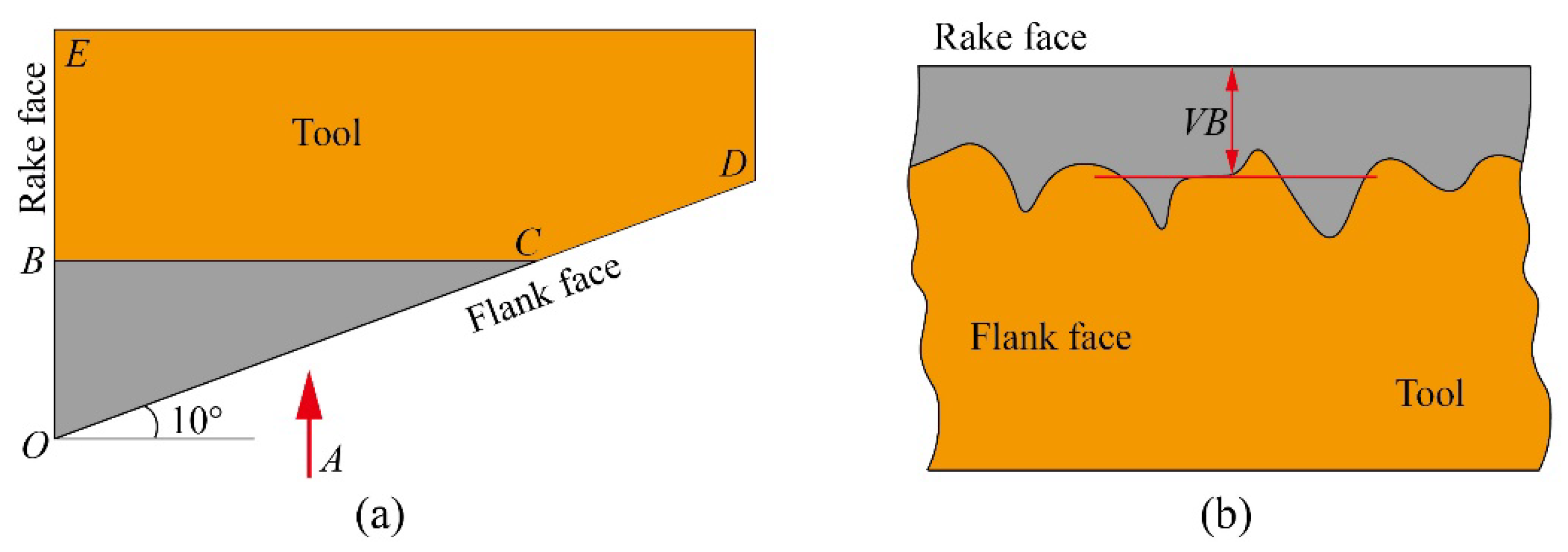
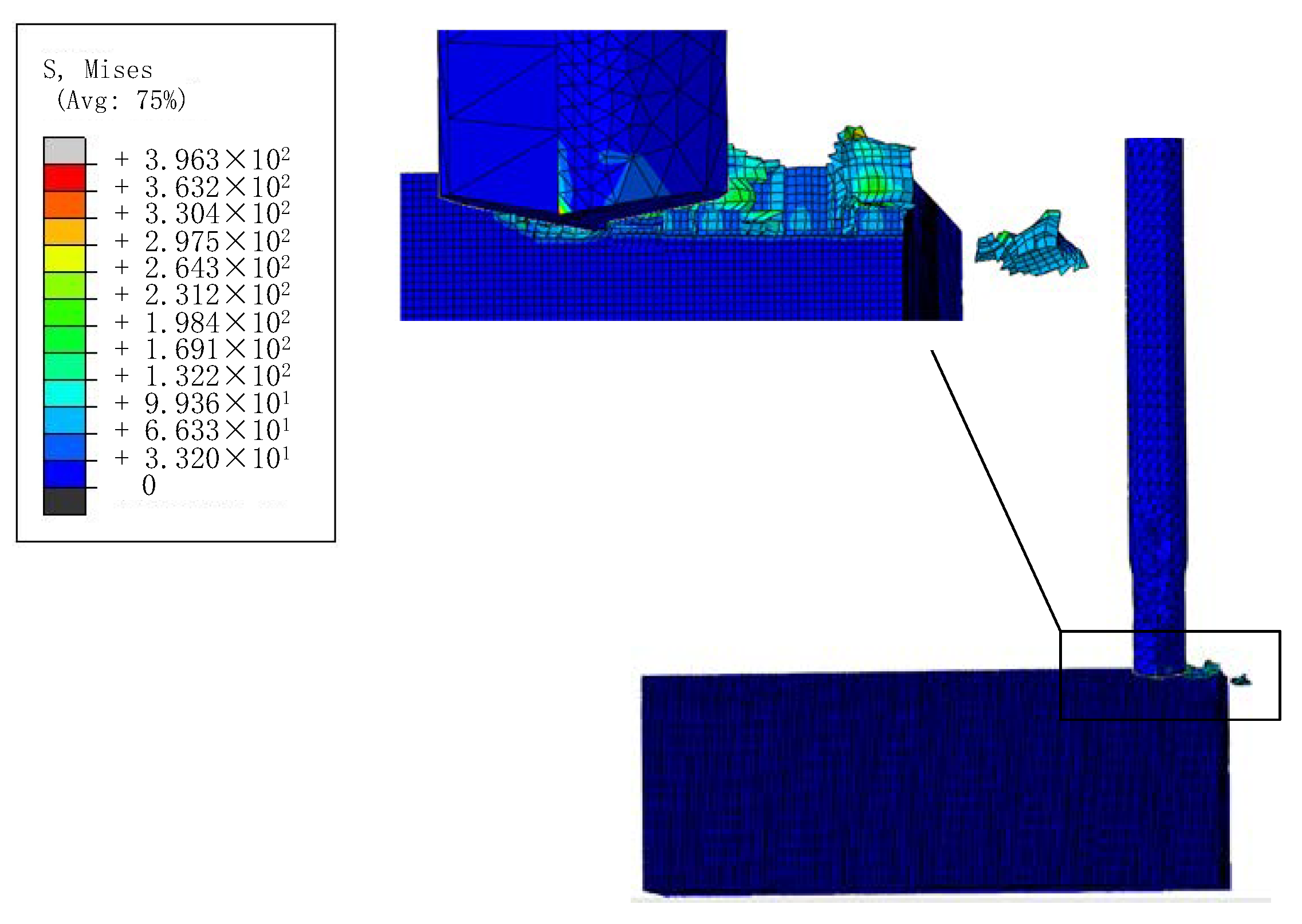
3.4. Model Validation with Experiments

In order to verify the validity of the prediction models, the experiments of milling zirconia ceramics by PCD tool were carried out in vertical drilling and tapping center TC500R. The experiments were repeated three times under the conditions of the optimal combination of machining parameters to obtain an average value. The results are shown in Table 6. According to the results of three experiments, the average values of F, VB and Q are 208.08 N, 29.24 μm, and 41.87 mm3/min, respectively. Compared with the predicted results, the relative errors of F, VB and Q are 11.38%, 12.46% and 6.23%, respectively, all less than 15%, which indicates that it is reasonable and feasible to use response surface method to optimize the machining parameters of milling zirconia ceramics by PCD tool.

4. Conclusions

In this paper, we established a finite element model to simulated milling zirconia ceramics by PCD tool. The influence of n, vf, ae and ap on F, VB and Q were studied. The response surface method was used to analyze and optimize the milling parameters. The second-order regression prediction models of F, VB and Q were established with the confidence level of each prediction model higher than 0.92. The influence of experimental factors on F, VB and Q is ap > n > vf >ae, ap > ae > n > vf and vf = ae = ap > n, respectively. When the multi-objective optimal machining parameters with F, VB and Q were under the same weight, the optimal parameters of n, vf, ae and ap are 8000 r/min, 90.65 mm/min, 0.10 mm, and 1.37 mm, respectively. Under this condition, F was 234.81 N, VB was 33.40 μm and Q was 44.65 mm3/min, when the milling length was 60 mm. Comparing the experimental and simulation results, the relative errors of F, VB and Q are 11.38, 12.46 and 6.23%, respectively. They are all smaller than 15% indicating that it is reasonable and feasible to use the response surface method to optimize the machining parameters of milling zirconia ceramics by PCD tool.

Author Contributions

Conceptualization, S.D. (Shuliang Dong) and L.A.; Methodology, X.Y. and S.D. (Shuliang Dong); Software, X.Y. and Z.Z.; Validation, X.L., Z.Z. and S.D. (Shuling Dong); Writing—original draft, X.Y., X.L. and S.D. (Shuling Dong); Writing—review & editing, S.D.(Shuliang Dong) and L.A. All authors have read and agreed to the published version of the manuscript.

Funding

This research was funded by Science and Technology Research Project of Higher Education Institutions in Hebei Province (QN2021117), Tangshan Basic research project (21130202C), and Tangshan talent foundation innovation team (20130204D).

Institutional Review Board Statement

Not applicable.

Informed Consent Statement

Not applicable.

Data Availability Statement

Not applicable.

Acknowledgments

This research was funded by Science and Technology Research Project of Higher Education Institutions in Hebei Province Grant No. QN2021117), Tangshan Basic research project (21130202C) and Tangshan talent foundation innovation team (20130204D).

Conflicts of Interest

The authors declare no conflict of interest.

References

  1. Zhang, X.; Wu, X.; Shi, J. Additive manufacturing of zirconia ceramics: A state-of-the-art review. J. Mater. Res. Technol. 2020, 9, 9029–9048. [Google Scholar] [CrossRef]
  2. Shahmiri, R.; Standard, O.C.; Hart, J.N.; Sorrell, C.C. Optical properties of zirconia ceramics for esthetic dental restorations: A systematic review. J. Prosthet. Dent. 2018, 119, 36–46. [Google Scholar] [CrossRef] [PubMed]
  3. Pekkan, G.; Pekkan, K.; Bayindir, B.Ç.; Özcan, M.; Karasu, B. Factors affecting the translucency of monolithic zirconia ceramics: A review from materials science perspective. Dent. Mater. J. 2020, 39, 1–8. [Google Scholar] [CrossRef] [PubMed] [Green Version]
  4. Luo, H.; Guo, M.; Yin, S.; Chen, F.; Huang, S.; Lu, A.; Guo, Y. An atomic-scale and high efficiency finishing method of zirconia ceramics by using magnetorheological finishing. Appl. Surf. Sci. 2018, 444, 569–577. [Google Scholar] [CrossRef]
  5. Xiao, X.; Zheng, K.; Liao, W.; Meng, H. Study on cutting force model in ultrasonic vibration assisted side grinding of zirconia ceramics. Int. J. Mach. Tool Manu. 2016, 104, 58–67. [Google Scholar] [CrossRef]
  6. Piconi, C.; Maccauro, G. Zirconia as a ceramic biomaterial. Biomaterials 1999, 20, 1–25. [Google Scholar] [CrossRef]
  7. Manicone, P.F.; Iommetti, P.R.; Raffaelli, L. An overview of zirconia ceramics: Basic properties and clinical applications. J. Dent. 2007, 35, 819–826. [Google Scholar] [CrossRef]
  8. Pagano, S.; Lombardo, G.; Caponi, S.; Costanzi, E.; Di Michele, A.; Bruscoli, S.; Xhimitiku, I.; Coniglio, M.; Valenti, C.; Mattarelli, M. Bio-mechanical characterization of a CAD/CAM PMMA resin for digital removable prostheses. Dent. Mater. 2021, 37, e118–e130. [Google Scholar] [CrossRef]
  9. Shanyong, L.; Yuling, W.; Shufeng, S.; Jing, S.; Qingyu, L.; Jin, W. Characterization and mechanism of porous silicon carbide ceramics processed by high temperature chemical corrosion. J. Aeronaut. Mater. 2019, 39, 16–24. [Google Scholar]
  10. Pan, P.; Wang, X.; Ji, Y.; Dong, W.; Zhang, L.; Wang, L.; Zhang, M. One-step synthesis of ZrO2 nanopowders dispersed with graphene by ball milling. Ceram. Int. 2020, 46, 24799–24804. [Google Scholar] [CrossRef]
  11. Xu, J.; Li, L.; Chen, M.; Paulo Davim, J. An experimental investigation on milling features of fully-sintered zirconia ceramics using PCD tools. Mater. Manuf. Processes 2021, 1–9. [Google Scholar] [CrossRef]
  12. Na, Y.; Lee, U.S.; Kim, B.H. Experimental Study on Micro-Grinding of Ceramics for Micro-Structuring. Appl. Sci. 2021, 11, 8119. [Google Scholar] [CrossRef]
  13. Lindvall, R.; Lenrick, F.; Persson, H.; M’Saoubi, R.; Ståhl, J.-E.; Bushlya, V. Performance and wear mechanisms of PCD and pcBN cutting tools during machining titanium alloy Ti6Al4V. Wear 2020, 454, 203329. [Google Scholar] [CrossRef]
  14. Huang, H.; Liu, Y. Experimental investigations of machining characteristics and removal mechanisms of advanced ceramics in high speed deep grinding. Int. J. Mach. Tool Manu. 2003, 43, 811–823. [Google Scholar] [CrossRef]
  15. Bian, R.; Ferraris, E.; He, N.; Reynaerts, D. Process investigation on meso-scale hard milling of ZrO2 by diamond coated tools. Precis. Eng. 2014, 38, 82–91. [Google Scholar] [CrossRef]
  16. Ferraris, E.; Mestrom, T.; Bian, R.; Reynaerts, D.; Lauwers, B. Machinability investigation on high speed hard turning of ZrO2 with PCD tools. Procedia CIRP 2012, 1, 500–505. [Google Scholar] [CrossRef]
  17. Bian, R.; Ding, W.; Liu, S.; He, N. Research on high performance milling of engineering ceramics from the perspective of cutting variables setting. Materials 2019, 12, 122. [Google Scholar] [CrossRef] [Green Version]
  18. Rong, B.; He, N.; Wenzheng, D.; Liu, S. A study on the tool wear of PCD micro end mills in ductile milling of ZrO2 ceramics. Int. J. Adv. Manuf. Technol. 2017, 92, 2197–2206. [Google Scholar]
  19. Wan, L.; Li, L.; Deng, Z.; Deng, Z.; Liu, W. Thermal-mechanical coupling simulation and experimental research on the grinding of zirconia ceramics. J. Manuf. Process 2019, 47, 41–51. [Google Scholar] [CrossRef]
  20. Li, C.; Hou, Y.; Liu, Z.; Ding, Y. Investigation into temperature field of nano-zirconia ceramics precision grinding. Int. J. Abras. Technol. 2011, 4, 77–89. [Google Scholar] [CrossRef]
  21. Jianxun, X.; Quanping, S. Analysis on Finite Element Simulation with Zirconia Ceramic in Cutting Processing. China Ceram. 2012, 10. [Google Scholar]
  22. Deng, B.; Yang, M.; Zhou, L.; Wang, H.; Yan, R.; Peng, F. Smoothed particle hydrodynamics (SPH) simulation and experimental investigation on the diamond fly-cutting milling of zirconia ceramics. Procedia CIRP 2019, 82, 202–207. [Google Scholar] [CrossRef]
  23. Murugesan, M.; Jung, D.W. Johnson Cook material and failure model parameters estimation of AISI-1045 medium carbon steel for metal forming applications. Materials 2019, 12, 609. [Google Scholar] [CrossRef] [PubMed] [Green Version]
  24. Wang, C.; Wang, X.; Sun, F. Tribological behavior and cutting performance of monolayer, bilayer and multilayer diamond coated milling tools in machining of zirconia ceramics. Surf. Coat. Technol. 2018, 353, 49–57. [Google Scholar] [CrossRef]
  25. Binder, M.; Klocke, F.; Döbbeler, B. An advanced numerical approach on tool wear simulation for tool and process design in metal cutting. Simul. Model. Pract. Th. 2017, 70, 65–82. [Google Scholar] [CrossRef]
  26. Zeilmann, R.P.; Zanella, C. PCD coating polishing effect on the tool wear in high-speed milling of graphite. Int. J. Adv. Manuf. Technol. 2020, 108, 2579–2593. [Google Scholar] [CrossRef]
  27. Liu, Z.; Zhao, R.; Liu, X.; Chen, L. Contract designing for a supply chain with uncertain information based on confidence level. Appl. Soft Comput. 2017, 56, 617–631. [Google Scholar] [CrossRef]
  28. Miraboutalebi, S.M.; Nikouzad, S.K.; Peydayesh, M.; Allahgholi, N.; Vafajoo, L.; McKay, G. Methylene blue adsorption via maize silk powder: Kinetic, equilibrium, thermodynamic studies and residual error analysis. Process Saf. Environ. Prot. 2017, 106, 191–202. [Google Scholar] [CrossRef]
  29. Greenland, S.; Senn, S.J.; Rothman, K.J.; Carlin, J.B.; Poole, C.; Goodman, S.N.; Altman, D.G. Statistical tests, P values, confidence intervals, and power: A guide to misinterpretations. Eur. J. Epidemiol. 2016, 31, 337–350. [Google Scholar] [CrossRef] [PubMed] [Green Version]
Figure 1. Milling schematic diagram.
Materials 15 00208 g001
Figure 2. Schematic illustration of tool wear. (a) Tool wear cross section, (b) A-direction view.
Materials 15 00208 g002
Figure 3. Schematic diagram of simulation results.
Materials 15 00208 g003
Figure 4. Response surface of spindle speed and feed rate on cutting force, tool flank wear and material removal rate. (a) Cutting force F, (b) Tool flank wear VB, (c) Material removal rate Q.
Materials 15 00208 g004
Figure 5. Response surface of radial depth of cut and axial depth of cut on cutting force, tool flank wear and material removal rate. (a) Cutting force F, (b) Tool flank wear VB, (c) Material removal rate Q.
Materials 15 00208 g005
Figure 6. The relation between predicted and simulated values. (a) Cutting force F, (b) Tool flank wear VB, (c) Material removal rate Q.
Materials 15 00208 g006
Table 1. Johnson-Cook constitutive model parameters for zirconia ceramics [22].
A/MPaB/MPaCnmTr/°CTm/°C
93031000.60.6251725
Table 2. Physical properties of workpiece and tool.
MaterialElastic Modulus E/(Pa)Poisson’s Ratio
μ
Thermal Conductivity κ/(W/m·K)Heat Capacity
c/(J/kg·K)
Density
ρ/(kg/m3)
Zirconia ceramics2.39 × 10110.32.64006050
PCD1.2 × 10120.21500471.53520
Table 3. Test factors level.
No.Control FactorsLevel
−2−1012
1n/(r/min)40005000600070008000
2vf/(mm/min)20406080100
3ae/(mm)0.030.060.090.120.15
4ap/(mm)0.61.21.82.43.0
There are four factors, according to central composite design, so the numbers of corner points are 16. The total number of experiments was 30.
Table 4. Simulation results of zirconia ceramic milling.
No.n/(r/min)vf/(mm/min)ae/(mm)ap/(mm)F/(N)VB/(μm)Q/(mm3/min)
15000800.122.4396.29107.3123.04
24000600.091.8332.622.709.72
35000400.062.4210.37102.735.76
46000600.090.6179.588.253.24
57000800.121.2219.7579.3911.52
65000400.121.2177.6281.925.76
76000600.091.8202.4389.443.24
87000400.121.2141.08116.975.76
98000600.091.8146.7986.319.72
107000400.061.2106.0879.432.88
1160001000.091.8311.3286.1816.2
127000400.062.4171.49142.525.76
137000800.122.4324.96143.5223.04
146000200.091.8169.13117.323.24
157000400.122.4271.42174.3011.52
167000800.062.4222.31108.5411.52
176000600.151.8261.54167.5116.2
186000600.091.8219.7386.459.72
196000600.031.8134.0364.753.24
206000600.091.8205.13106.899.72
217000800.061.2178.2827.845.76
226000600.091.8187.1990.349.72
235000800.061.2187.8654.755.76
245000800.121.2184.7176.4611.52
256000600.091.8227.9482.349.72
266000600.093.0356.75175.3316.2
275000800.062.4321.5352.8511.52
286000600.091.8206.9584.909.72
295000400.122.4331.63116.2911.52
305000400.061.2226.9558.302.88
Table 5. Analysis of variance of regression prediction models.
SourceFVBQ
Sum of SquaresdfSum of SquaresdfMean SquareF-Valuep-ValueMean SquareF-Valuep-ValueSum of SquaresdfMean SquareF-Valuep-Value
Model143,0001448,094.43143435.3212.70<0.00013435.3212.70<0.0001811.811081.18743.85<0.0001
n 24,913.1516309.5816309.5823.330.00026309.5823.330.00020.0010.001.041.0000
v f 19,461.5213372.0413372.0412.470.00303372.0412.470.0030251.941251.942308.50<0.0001
a e 19,131.4719389.1719389.1734.71<0.00019389.1734.71<0.0001251.941251.942308.50<0.0001
a p 58,214.49120,849.44120,849.4477.08<0.000120,849.4477.08<0.0001251.941251.942308.50<0.0001
n v f 775.761462.901462.901.710.2105462.901.710.2105
n a e 1147.691112.471112.470.420.5288112.470.420.5288
n a p 1184.9111552.3611552.365.740.03011552.365.740.0301
v f a e 4.921196.841196.840.730.4070196.840.730.4070 1
v f a p 1626.31140.01140.010.150.705940.010.150.7059
a e a p 8770.7910.0110.010.000.99450.010.000.9945
n 2 1235.2912897.5012897.5010.700.00522897.5010.700.0052
v f 2 1283.611445.421445.421.650.2189445.421.650.2189
a e 2 389.651389.650.540.47361598.2911598.295.910.0281
a p 2 5243.1515243.157.270.016665.03165.030.240.6310
Residual10,813.1515720.884057.1115270.472.07190.11
Lack of Fit3676.1410367.614.860.04743676.1410367.614.820.04820.00140.15
Pure Error1008.305210.66380.97576.19813.8950.00
Cor Total153,8002952,151.5429 29
Table 6. Verify the results of the experiment.
123AveragePredicted Value
F/(N)208.81221.69193.75208.08234.81
VB/(μm)29.6730.8427.2229.2433.40
Q/(mm3/min)38.4040.3047.1041.8744.65
Publisher’s Note: MDPI stays neutral with regard to jurisdictional claims in published maps and institutional affiliations.

