
Clinching of Thermoplastic Composites and Metals—A Comparison of Three Novel Joining Technologies

 , , , , ,

Abstract
1. Introduction
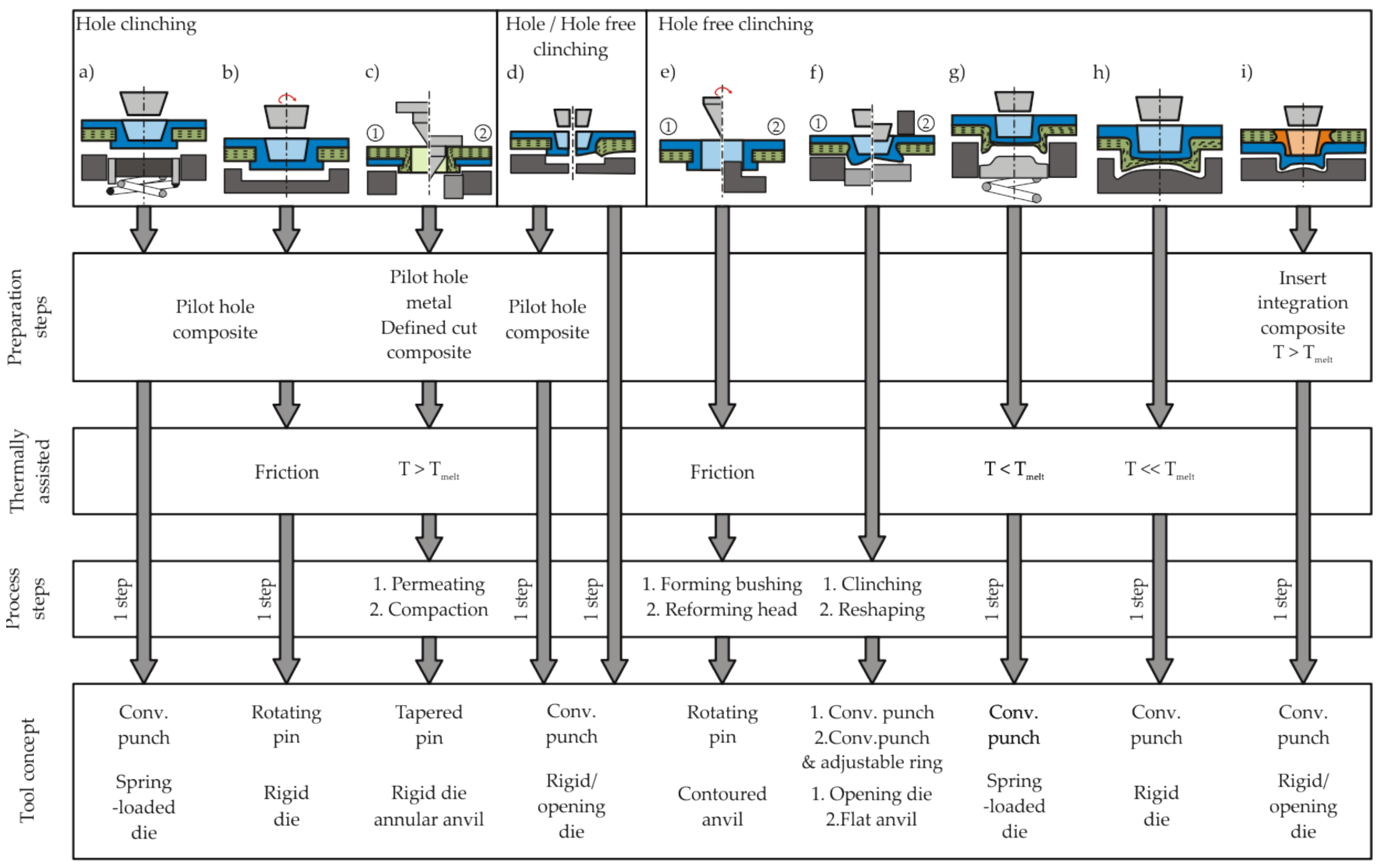
2. Process
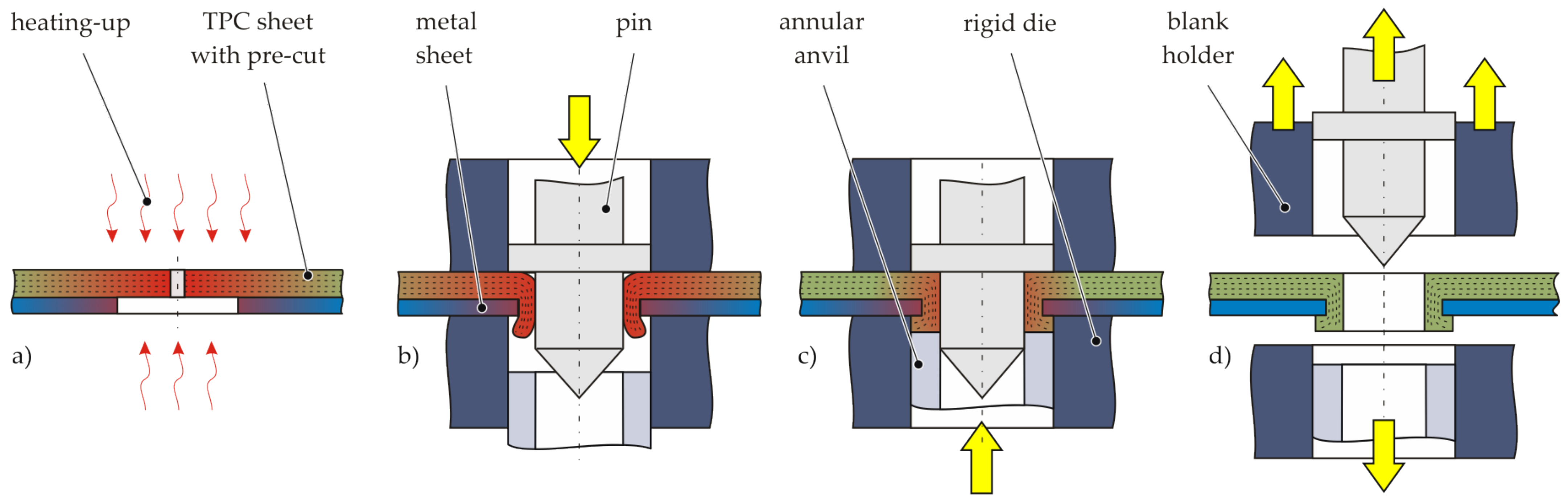
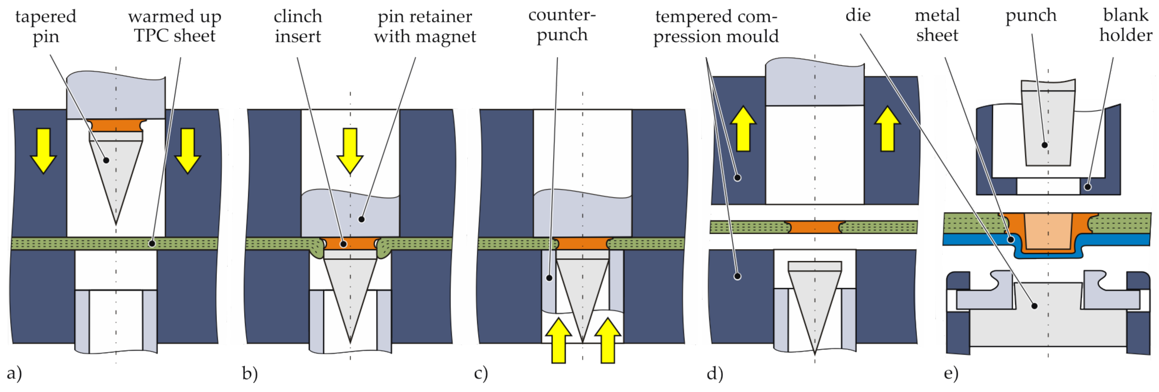
2.1. Thermochlinching
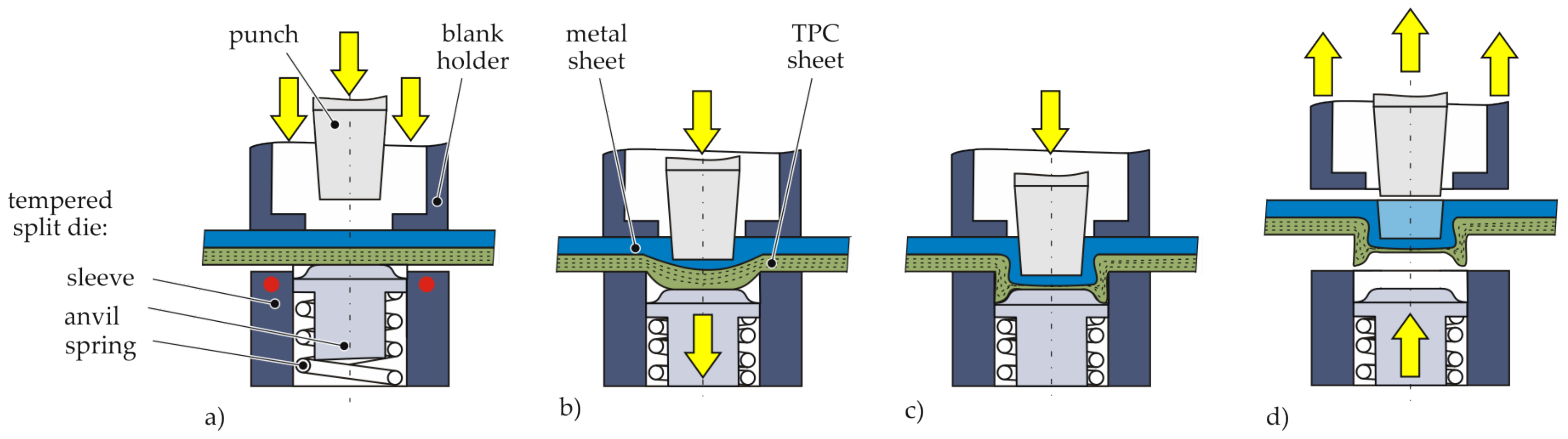
2.2. Hotclinching
2.3. Insert Clinching
3. Materials and Methods
3.1. Material Specification
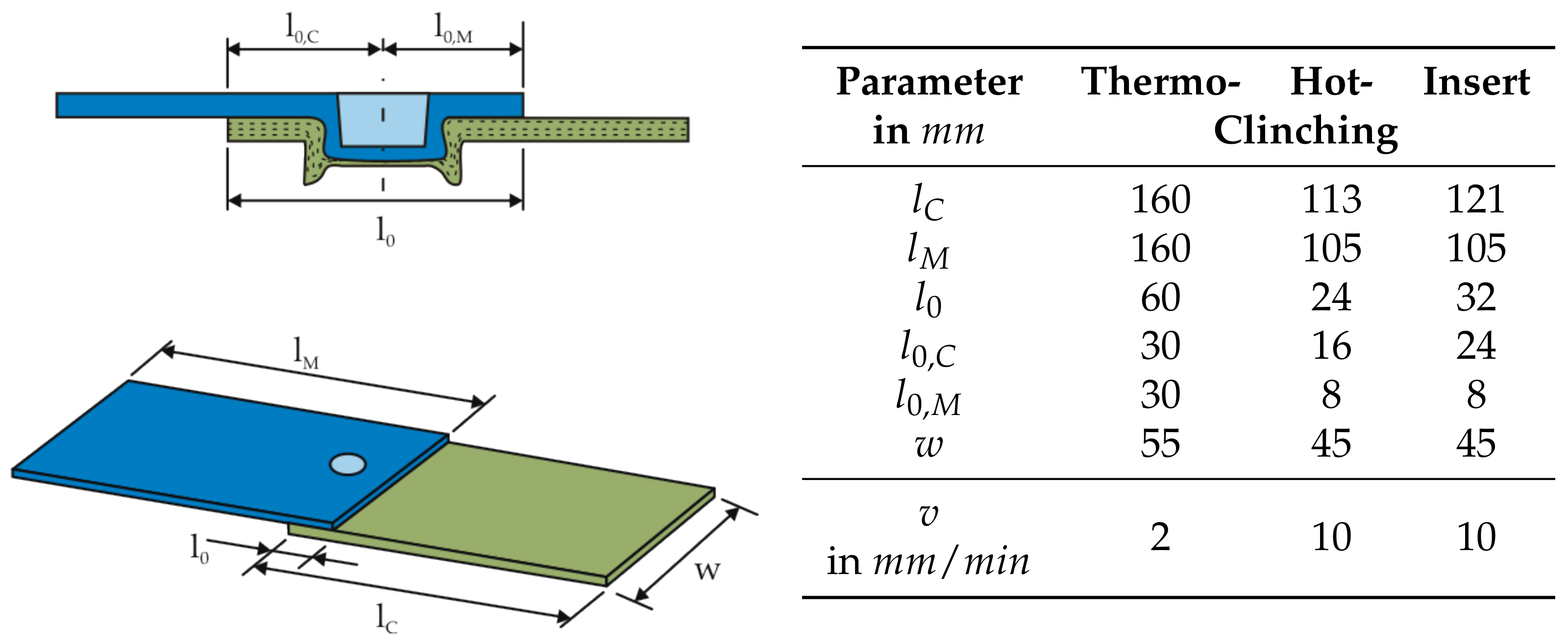
3.2. Equipment and Characteristic Dimensions
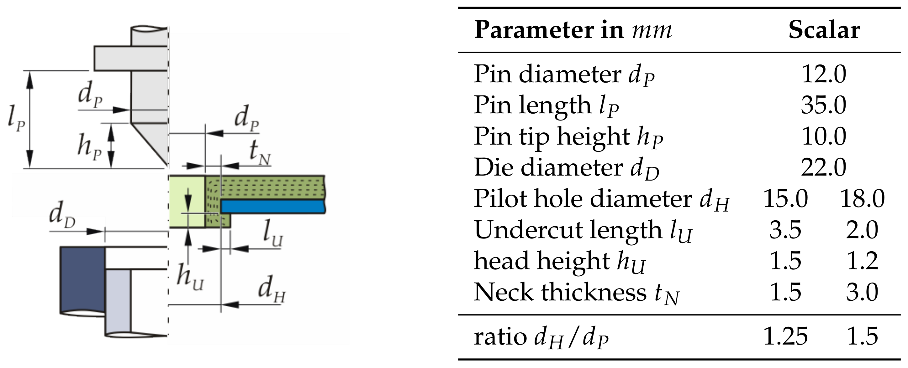
Thermoclinching
Hotclinching
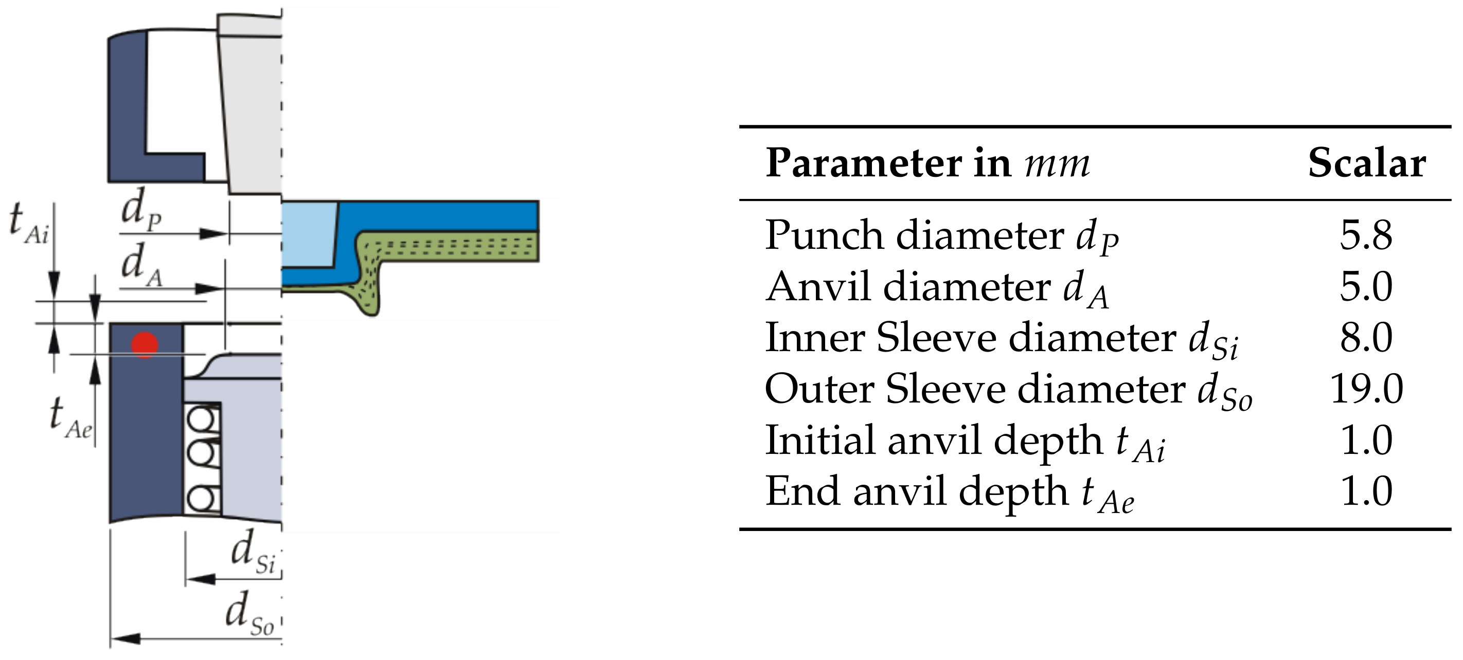
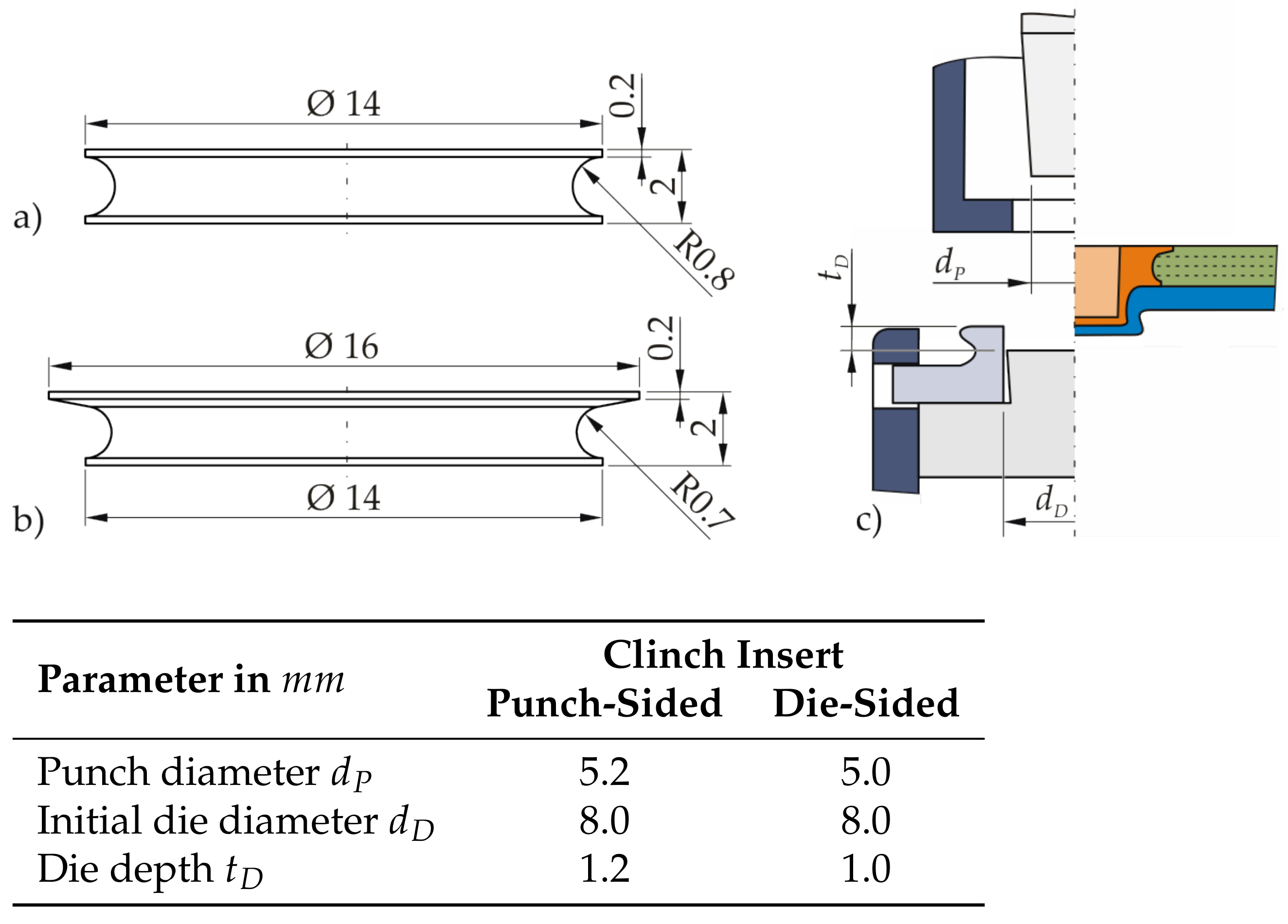
Insert Clinching
3.3. Evaluation Methods
4. Process Phenomena
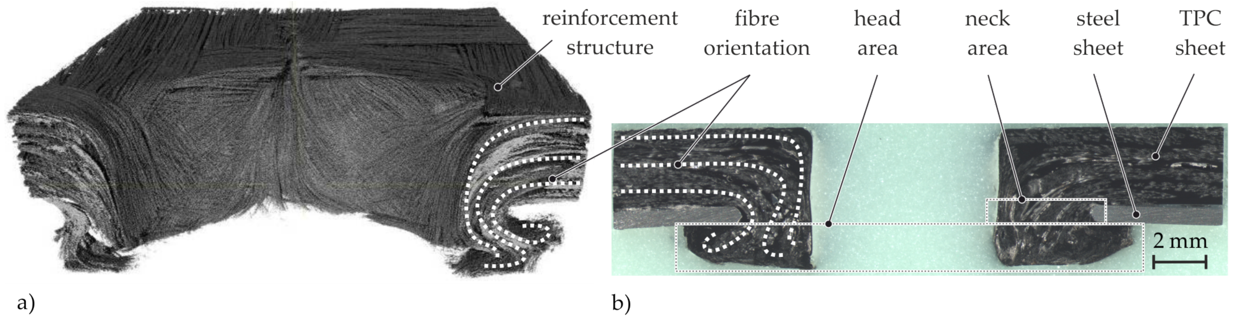
4.1. Thermoclinching
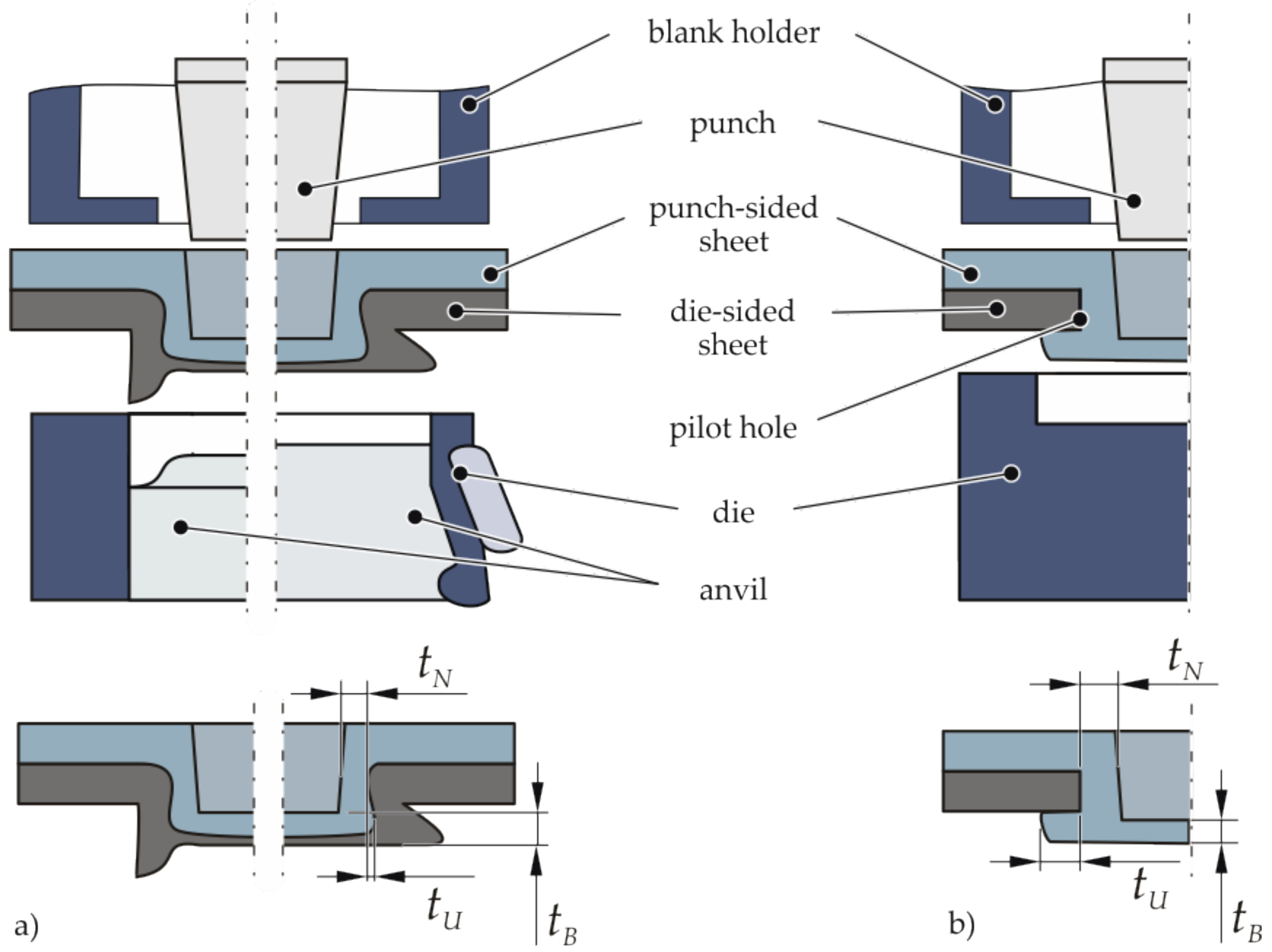
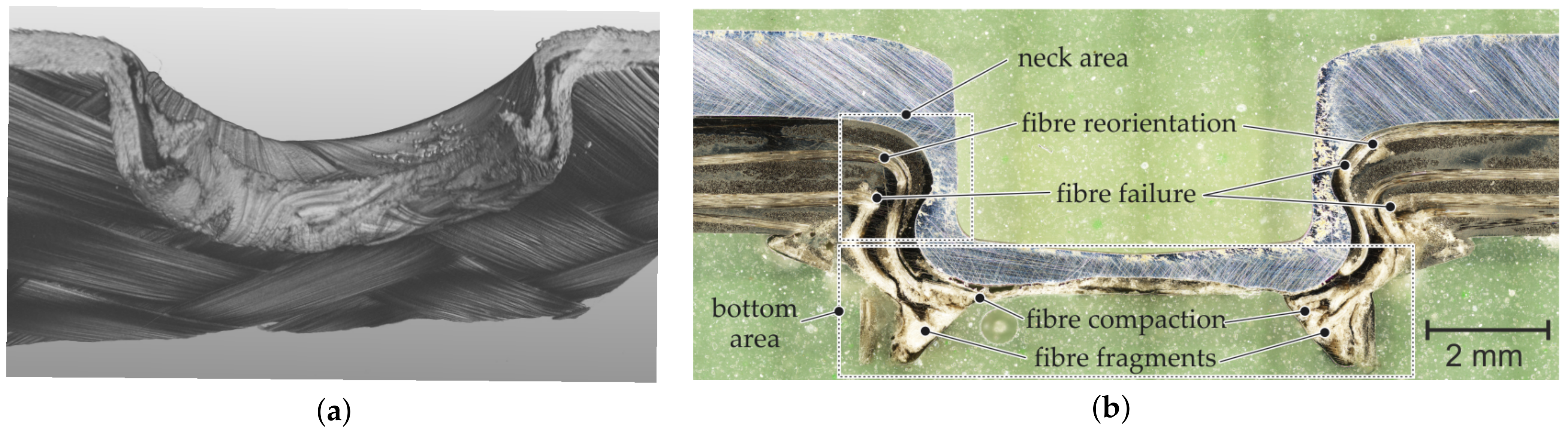
4.2. Hotclinching
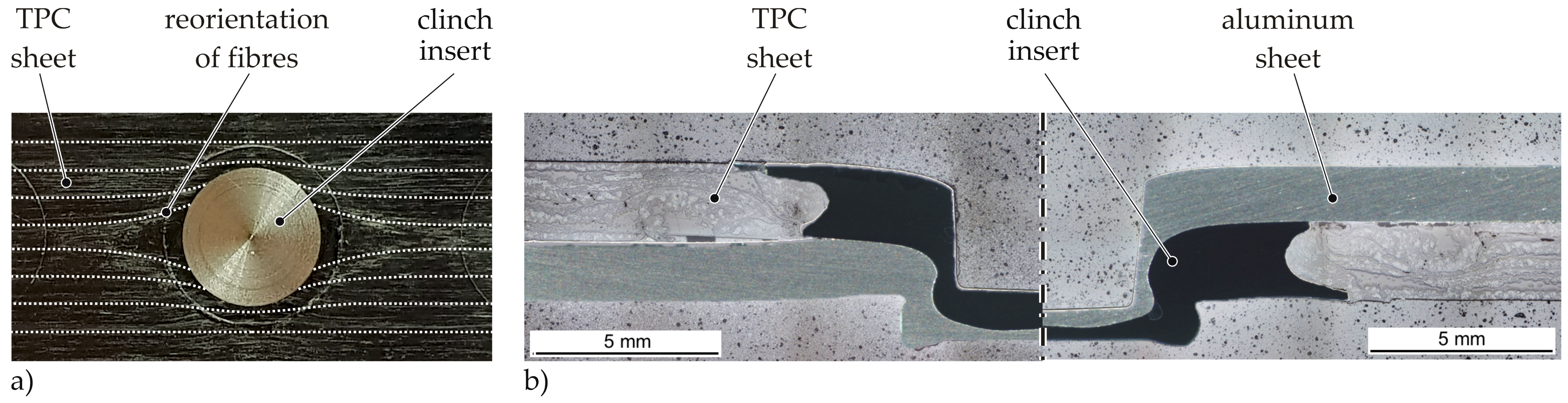
4.3. Insert Clinching
5. Load Bearing Behaviour
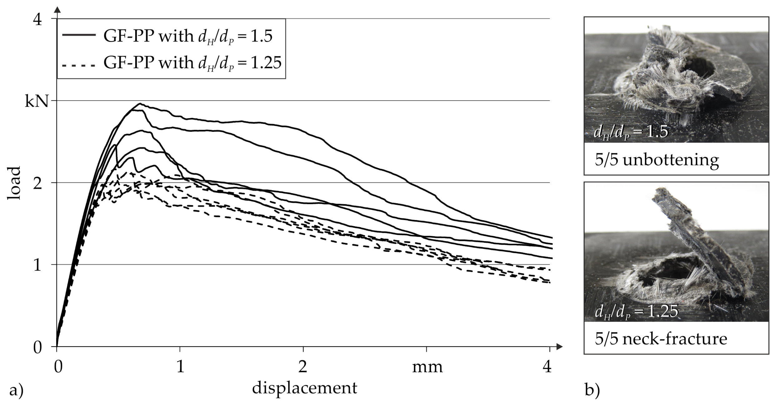
5.1. Thermoclinching
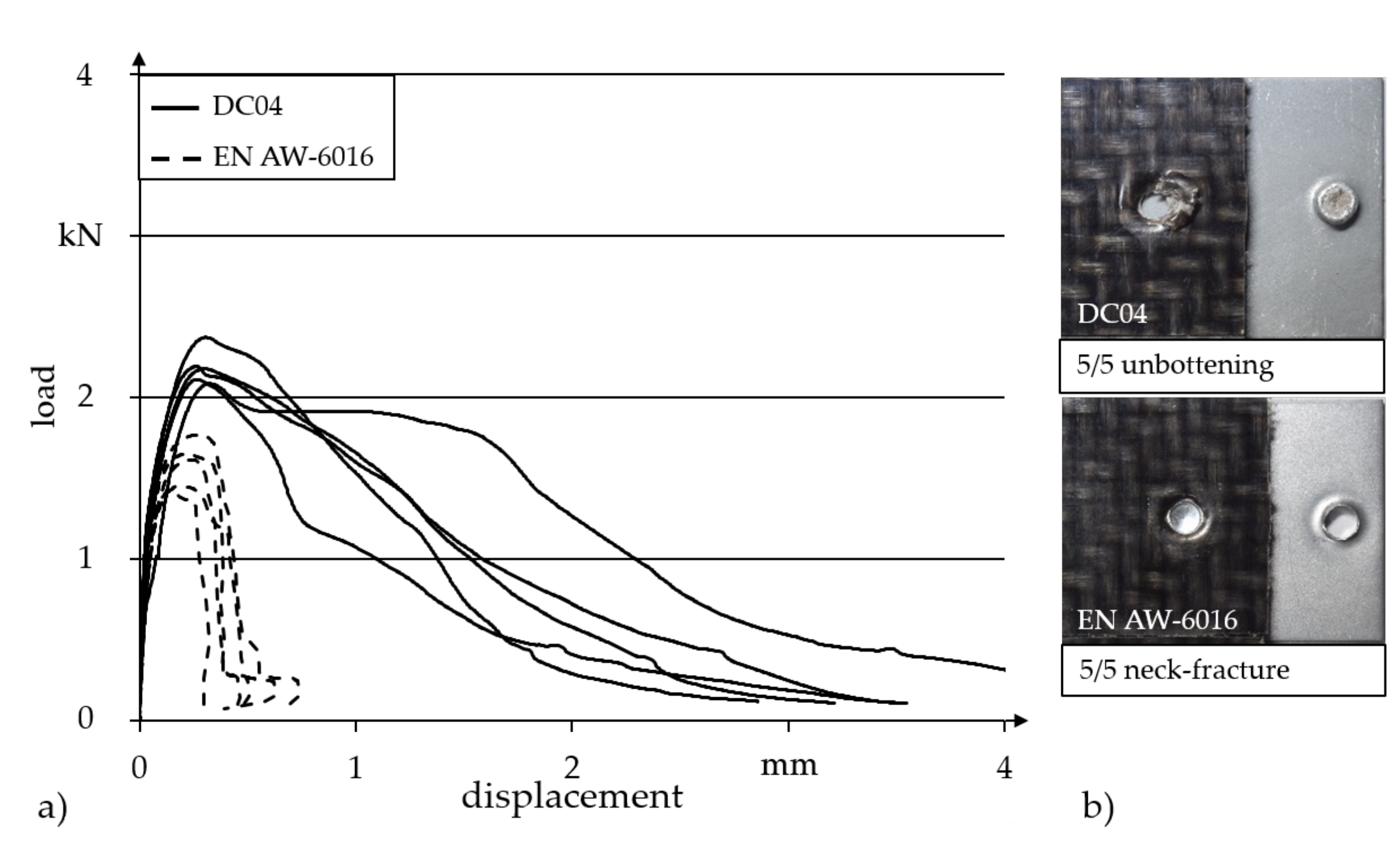
5.2. Hotclinching
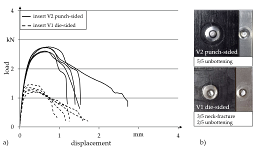
5.3. Insert Clinching
6. Discussion
7. Conclusions
Author Contributions
Funding
Institutional Review Board Statement
Informed Consent Statement
Data Availability Statement
Conflicts of Interest
Abbreviations
| Al | Aluminium |
| Al-CFRP | Aluminum-carbon fibre reinforced plastic |
| Al-GFRP | Aluminum-glass fibre reinforced plastic |
| CFRP | Carbon fibre reinforced plastic |
| CT | Computed tomography |
| GF-PP | glass fibre reinforced polypropylene |
| GF-PA6 | glass fibre reinforced polyamid 6 |
| TPC | Thermoplastic composites |
References
- Lambiase, F.; Scipioni, S.I.; Ko, D.-C.; Liu, F. A State-of-the-Art Review on Advanced Joining Processes for Metal-Composite and Metal-Polymer Hybrid Structures. Materials 2021, 14, 1890. [Google Scholar] [CrossRef]
- Eshtayeh, M.M.; Hrairi, M.; Mohiuddin, A.K.M. Clinching process for joining dissimilar materials: State of the art. Int. J. Adv. Manuf. Technol. 2016, 82, 179–195. [Google Scholar] [CrossRef]
- Kascak, L.; Spisak, E.; Majernikova, J. Clinching and Clinch-Riveting as a Green Alternative to Resistance Spot Welding. In Proceedings of the International Council on Technologies of Environmental Protection (ICTEP), Starý Smokovec, Slovakia, 23–25 October 2019; pp. 138–142. [Google Scholar]
- Mucha, J. Clinching technology in the automotive industry. Arch. Automot. Eng. 2017, 76, 75–94. [Google Scholar]
- Lee, C.-J.; Lee, J.-M.; Ryu, H.-Y.; Lee, K.-H.; Kim, B.-M.; Ko, D.-C. Design of hole-clinching process for joining of dissimilar materials—Al6061-T4 alloy with DP780 steel, hot-pressed 22MnB5 steel, and carbon fiber reinforced plastic. J. Mater. Process. Technol. 2014, 214, 2169–2178. [Google Scholar] [CrossRef]
- Lee, C.-J.; Lee, S.-H.; Lee, J.-M.; Kim, B.-H.; Ko, D.-C. Design of Hole-Clinching Process for Joining CFRP and Aluminum Alloy Sheet. Int. J. Precis. Eng. Manuf. 2014, 14, 1151–1157. [Google Scholar] [CrossRef]
- Lee, S.-H.; Lee, C.-J.; Kim, B.-H.; Ahn, M.-S.; Kim, B.-M.; Ko, D.-C. Effect of Tool Shape on Hole Clinching for CFRP with Steel and Aluminum Alloy Sheet. Key Eng. Mater. 2014, 622–623, 476–483. [Google Scholar] [CrossRef]
- Lee, C.-J.; Kim, B.-M.; Kang, B.-S.; Song, W.-J.; Ko, D.-C. Improvement of joinability in a hole clinching process with aluminum alloy and carbon fiber reinforced plastic using a spring die. Compos. Struct. 2017, 173, 58–69. [Google Scholar] [CrossRef]
- Lambiase, F.; Paoletti, A. Friction-assisted clinching of Aluminum and CFRP sheets. J. Manuf. Process. 2018, 31, 812–822. [Google Scholar] [CrossRef]
- Lambiase, F. Mechanical behaviour of polymer–metal hybrid joints produced by clinching using different tools. Mater. Des. 2015, 87, 606–618. [Google Scholar] [CrossRef]
- Lambiase, F.; Durante, M.; Ilio, A.D. Fast joining of aluminum sheets with Glass Fiber Reinforced Polymer (GFRP) by mechanical clinching. J. Mater. Process. Technol. 2016, 236, 241–251. [Google Scholar] [CrossRef]
- Lambiase, F.; Ko, D.-C. Feasibility of mechanical clinching for joining aluminum AA6082-T6 and Carbon Fiber Reinforced Polymer sheets. Mater. Des. 2016, 107, 341–352. [Google Scholar] [CrossRef]
- Lambiase, F.; Ko, D.-C. Two-steps clinching of aluminum and Carbon Fiber Reinforced Polymer sheets. Compos. Struct. 2017, 164, 180–188. [Google Scholar] [CrossRef]
- Lin, P.C.; Lin, J.W.; Li, G.X. Clinching process for aluminum alloy and carbon fiber-reinforced thermoplastic sheets. Int. J. Adv. Manuf. Technol. 2018, 97, 529–541. [Google Scholar] [CrossRef]
- Seidlitz, H.; Ulke-Winter, L.; Kroll, L. New Joining Technology for Optimized Metal/Composite Assemblies. J. Eng. 2014, 1–11. [Google Scholar] [CrossRef]
- Gude, M.; Hufenbach, W.; Kupfer, R.; Freund, A.; Vogel, C. Development of novel form-locked joints for textile reinforced thermoplastices and metallic components. J. Mater. Process. Technol. 2015, 216, 140–145. [Google Scholar] [CrossRef]
- Vorderbrüggen, J.; Gröger, B.; Kupfer, R.; Hoog, A.; Gude, M.; Meschut, G. Phenomena of forming and failure in joining hybrid structures—Experimental and numerical studies of clinching thermoplastic composites and metal. AIP Conf. Proc. 2019, 2113, 050016. [Google Scholar]
- Rotheiser, J. Joining of Plastics: Handbook for Designers and Engineers, 3rd ed.; Carl Hanser Verlag GmbH Co. KG: Munich, Germany, 2009; p. 451. [Google Scholar]
- Troschitz, J.; Kupfer, R.; Gude, M. Experimental investigation of the load bearing capacity of inserts embedded in thermoplastic composites. In Proceedings of the 4th International Conference Hybrid 2020 Materials and Structures, Web Conference, Karlsruhe, Germany, 28–29 April 2020; pp. 249–254. [Google Scholar]
- Troschitz, J.; Kupfer, R.; Gude, M. Process-integrated embedding of metal inserts in continuous fibre reinforced thermoplastics. Procedia CIRP 2019, 85, 84–89. [Google Scholar] [CrossRef]
- Troschitz, J.; Vorderbrüggen, J.; Kupfer, R.; Gude, M.; Meschut, G. Joining of Thermoplastic Composites with Metals Using Resistance Element Welding. Appl. Sci. 2020, 10, 7251. [Google Scholar] [CrossRef]
- Tenorio, M.B.; Lajarin, S.F.; Gipiela, M.L.; Marcondes, P.V.P. The influence of tool geometry and process parameters on joined sheets by clinching. J. Braz. Soc. Mech. Sci. Eng. 2019, 41, 1–11. [Google Scholar] [CrossRef]
- He, X.M. Clinching for sheet materials. Sci. Technol. Adv. Mater. 2017, 18, 381–405. [Google Scholar] [CrossRef]
- Lambiase, F.; Di Ilio, A. An experimental study on clinched joints realized with different dies. Thin-Walled Struct. 2014, 85, 71–80. [Google Scholar] [CrossRef]
- Coppieters, S.; Zhang, H.; Xu, F.; Vandermeiren, N.; Breda, A.; Debruyne, D. Process-induced bottom defects in clinch forming: Simulation and effect on the structural integrity of single shear lap specimens. Mater. Des. 2017, 130, 336–348. [Google Scholar] [CrossRef]
- Abibe, A.B.; Amancio-Filho, S.T.; dos Santos, J.F.; Hage, E. Mechanical and failure behaviour of hybrid polymer–metal staked joints. Mater. Des. 2013, 46, 338–347. [Google Scholar] [CrossRef]
- Babalo, V.; Fazli, A.; Soltanpour, M. Experimental study of the mechanical performance of the new high-speed mechanical clinching. Int. J. Lightweight Mater. Manuf. 2021, 4, 218–236. [Google Scholar]
- Galińska, A.; Galinski, C. Mechanical Joining of Fibre Reinforced Polymer Composites to Metals—A Review. Part II: Riveting, Clinching, Non-Adhesive Form-Locked Joints, Pin and Loop Joining. Polymers 2020, 12, 1681. [Google Scholar] [CrossRef] [PubMed]
- Deutsches Institut für Normung. DIN EN ISO 14273:2013. Specimen dimensions and procedure for shear testing resistance spot, seam and embossed projection welds (ISO/DIS 14273:2013); German version EN ISO 14273:2013.
- DVS/EFB 3480-1 Testing of Properties of Joints—Testing of Properties of Mechanical and Hybrid (Mechanical/Bonded) Joints; DVS: Düsseldorf, Germany, 2007.
- Deutsches Institut für Normung. ISO 527-4:1997. Plastics—Determination of tensile properties—Part 4: Test conditions for isotropic and anisotropic fibre-reinforced plastic composites (ISO 527-4:1997); German version EN ISO 527-4:1997. [CrossRef]
- Gude, M.; Vogel, C.; Gröger, B. Simulation-aided development of a robust thermoclinching joining process for hybrid structures with textile reinforced thermoplastic composites and metallic components. Mater. Werkst. 2019, 50, 1027–1038. [Google Scholar] [CrossRef]
- Song, Y.; Yang, L.; Zhu, G.; Hua, L.; Liu, R. Numerical and experimental study on failure behavior of steelaluminium mechanical clinched joints under multiple test conditions. Int. J. Lightweight Mater. Manuf. 2019, 2, 72–79. [Google Scholar]


| Thermoclinching | Hotclinching | Insert Clinching | ||
|---|---|---|---|---|
| TPC | Material | GF-PP | GF-PA6 | GF-PP |
| Configuration | twill fabric [(0/90)4]s | twill fabric [(0/90)2]s | UD [(0/90)4]s | |
| Fibre volume content | 35% | 47% | 45% | |
| Thickness | 4 mm | 2 mm | 2 mm | |
| Metal | Material | structural steel | steel DC04, EN AW-6016 T4 | EN AW-6016 T4 |
| Thickness | 1 mm | mm | mm | |
| Auxiliary insert | - | - | steel S235JR |
| Process | Thermoclinching Ratio | Hotclinching Joining Partner | Insert Clinching Insert Position | |||
|---|---|---|---|---|---|---|
| 1.25 | 1.5 | Steel | Aluminum | Punch-Sided | Die-Sided | |
| Neck thickness in | 1.5 | 3.0 | 0.66 ± 0.02 | 0.62 ± 0.03 | 0.48 ± 0.02 | 0.29 ± 0.02 |
| Undercut in | 3.5 | 2.0 | 0.39 ± 0.01 | 0.36 ± 0.01 | 0.22 ± 0.02 | 0.18 ± 0.01 |
| Shear load in | 2.0 ± 0.1 | 2.9 ± 0.1 | 2.2 ± 0.1 | 1.6 ± 0.1 | 2.7 ± 0.1 | 1.3 ± 0.1 |
| Failure mode | neck fracture | unbuttoning | unbuttoning | neck fracture | unbuttoning | neck fracture |
| Technology | Material | Thickness in mm | Shear Load in kN |
|---|---|---|---|
| (a) Improved hole clinching [8] | Al/ thermoset CFRP | 1.4/1.0 | |
| (b) Friction assisted clinching [9] | Al/thermoset CFRP | 2.0/2.0 | up to |
| (c) Thermoclinching [16] | steel/GF-PP | 1.0/4.0 | |
| (d) Clinching-hole [6] | Al/thermoset CFRP | 2.4/1.0–1.6 | up to |
| (d) Clinching-hole free [11] | Al (AA6082-T6)/thermoset GFRP | 2.0/2.0 | |
| Al (AA5086)/thermoset GFRP | 2.0 & 3.0/2.0 | up to | |
| (d) Clinching-hole free [12] | Al/thermoset CFRP | 2.0/1.4 | |
| (e) Flow Drill Joining [15] | steel/CF-PA6 | 1.5/1.5 | |
| steel/GF-PP | 1.5/1.0 | ||
| (f) Two-Step Clinching [13] | Al/thermoset CFRP | 3.0/1.4 | |
| (g) Hotclinching [17] | steel/GF-PA6 | 1.5/2.0 | |
| Al/GF-PA6 | 1.5/2.0 | ||
| (h) Preheated Clinching [14] | Al/CF-TPC | 1.6/1.6 | |
| (i) Insert Clinching | Al/GF-PP | 1.5/2.0 | up to |
| Criterion | Thermoclinching | Hotclinching | Insert Clinching |
|---|---|---|---|
| Joining direction | TPC to metal | metal to TPC | both |
| Clinch | 30 s (heating) | 16 s (heating) | <5 s |
| process time | +1 s (joining) | +3 s (joining) | (standard metal |
| +30 s (consolidation) | clinching) | ||
| Complexity of the clinch tool | tapered pin/rigid die & annular anvil | conventional punch/spring-loaded die with heat source | conventional tools |
| Positioning accuracy | no requirements |
Publisher’s Note: MDPI stays neutral with regard to jurisdictional claims in published maps and institutional affiliations. |
© 2021 by the authors. Licensee MDPI, Basel, Switzerland. This article is an open access article distributed under the terms and conditions of the Creative Commons Attribution (CC BY) license (https://creativecommons.org/licenses/by/4.0/).
Share and Cite
Gröger, B.; Troschitz, J.; Vorderbrüggen, J.; Vogel, C.; Kupfer, R.; Meschut, G.; Gude, M. Clinching of Thermoplastic Composites and Metals—A Comparison of Three Novel Joining Technologies. Materials 2021, 14, 2286. https://doi.org/10.3390/ma14092286
Gröger B, Troschitz J, Vorderbrüggen J, Vogel C, Kupfer R, Meschut G, Gude M. Clinching of Thermoplastic Composites and Metals—A Comparison of Three Novel Joining Technologies. Materials. 2021; 14(9):2286. https://doi.org/10.3390/ma14092286
Chicago/Turabian StyleGröger, Benjamin, Juliane Troschitz, Julian Vorderbrüggen, Christian Vogel, Robert Kupfer, Gerson Meschut, and Maik Gude. 2021. "Clinching of Thermoplastic Composites and Metals—A Comparison of Three Novel Joining Technologies" Materials 14, no. 9: 2286. https://doi.org/10.3390/ma14092286
APA StyleGröger, B., Troschitz, J., Vorderbrüggen, J., Vogel, C., Kupfer, R., Meschut, G., & Gude, M. (2021). Clinching of Thermoplastic Composites and Metals—A Comparison of Three Novel Joining Technologies. Materials, 14(9), 2286. https://doi.org/10.3390/ma14092286