1. Introduction
Reinforced concrete structures are sometimes subjected to seismic and high impact loadings, which might cause catastrophic damage. An impact load might be an aircraft taking off or landing on a runway, or a heavy vehicle passing over a bridge expansion joint; in a harbor, a ship may collide with a wharf due to the movement of the waves. These impact loadings cause damage, such as cracks and spalling, to the reinforced concrete pavement. Generally, natural and manmade fibers incorporated into reinforced concrete structures can improve the durability and toughness and can reduce the shrinkage of concrete. Recently, carbon-fiber-reinforced mortar (CFRM) and carbon-fiber-reinforced concrete (CFRC) are usually being used in the repair, rehabilitation, and rebuilding work of civil engineering infrastructures.
Fiber-reinforced mortar (FRM) enhances the tensile and impact resistance, and fiber is used as reinforcement to increase its strength. Concrete is a brittle material and prone to cracks or damage when subjected to an external force, and the load-bearing capacity and its serviceability will be reduced. If the compression and impact resistance of concrete structures can be improved, then the service life of the various reinforced concrete structures can be prolonged. Fiber-reinforced concrete (FRC) has good mechanical properties and is used in multiple construction environments.
In the last few decades, many studies have been conducted on the performance of different fibers applied in mortar and concrete. Concrete reinforced by steel rebars and polypropylene fiber has shown an increase in mechanical performance on flexural strength and improved ability to impact resistance [
1]. Fiber-reinforced lightweight foamed concrete integrated with glass-fiber-reinforced plastics (GFRP) mesh was placed in the tensile region; the polymer fibers increased the flexural capacity of the beams, especially for the low-density specimens and for the higher contents of fibers [
2]. Glass-fiber-reinforced concrete with 1% volume fraction glass fiber can enhance flexural strength, and the impact resistance and mechanical properties are strengthened by different lengths of fiber and volume content [
3,
4,
5]. The various volume fraction and the water–cement ratios of silica fume incorporated with steel fibers can improve the ductility and impact resistance. It was also found that the impact resistance of reinforced concrete increased when silica fume and fine aggregate were replaced by cement and rubber fiber. The fiber-reinforced concrete proved that the energy absorption capacity of polypropylene was superior to that of cellulose [
6,
7].
Several studies reveal the effect of adding different fibers on the mechanical properties of fiber-reinforced concrete: The impact resistance of self-consolidating rubberized concrete (SCRC) can be determined by the reinforced steel fiber and synthetic semi-rigid fiber; the addition of synthetic semi-rigid fiber to self-filling rubber concrete can improve impact resistance. Geopolymer concrete reinforced with mono fiber has a remarkable enhancement in its impact strength and fracture toughness. It was concluded that the steel fiber–polypropylene fiber reinforced specimen has the best toughness, with a proportion of 1.5%, and it takes repeated impacts to reach complete failure [
8,
9,
10,
11].
Carbon fiber is a lightweight composite material, which does not corrode, degrade, or fatigue. Due to its high specific strength, it is used in the aerospace industry, for automotive parts and sports equipment, and in civil engineering. The content and length of carbon fiber in concrete affect performance on the strength of various aspects. As the amount and length of additive carbon fiber increases, the impact resistance significantly improves. The failure of fiber-reinforced concrete paste is mainly due to the force endured beyond the bonded force between surfaces [
12,
13,
14,
15,
16,
17]. The cement composites with uniformly distributed carbon fiber provide high efficiency, which was identified by an electron microscope. In addition, fiber-dispersion processes were examined with various studies in the cement composites [
18,
19,
20]. The chopped carbon fiber was treated for the removal of residual silane by using chemical and physical methods, and it was detected by GC/MS (Gas Chromatography/Mass Spectrometry) testing. The physical treatment exhibits high compressive strength of 14.1%, as compared with chemical treatment [
21]. The chopped fiber is a lightweight material, and its mechanical behavior is enhanced when mixed into concrete. The results show that the fiber is uniformly distributed, stress acts in a different direction, and the chopped fiber improves the composite material performance from the brittle failure [
22]. The multi-stage procedure was carried out with fiber contour modelling techniques and subsequent hierarchical multiscale analysis [
23]. Ultrasonic waves and vibration were used to improve the dispersion of carbon fiber in cement composites [
24]. The effect of the microstructure of CFRC on their macrostructure and the mechanical properties of CFRC specimens were investigated [
25]. The strength of the fiber-reinforced lightweight aggregate concrete increases with different fiber volume fractions embedded in the cementitious matrix [
26,
27,
28,
29].
Chopped carbon fiber was used in this study, to determine the static (compression and bending) and impact behavior of concrete and mortar with different lengths of fiber (6, 12, and 24 mm). The carbon fibers were separated by dispersion and then incorporated into the cement with a 1% weight proportion. A pneumatic process was additionally used to disperse the carbon fiber for uniform distribution in the concrete and mortar.
2. Materials
The carbon fibers were chopped at different lengths (6, 12, and 24 mm), which were uniformly mixed in slurry forms for mortar and concrete. In this section, the materials, experimental methods, and equipment are listed; they include various material properties of carbon fiber, aggregates, and cement. Carbon-fiber tensile strength and elastic modulus are superior to other fibers; the properties are listed in
Table 1, respectively. The data were obtained from the manufacturers and journal papers [
11,
30,
31]. The carbon-fiber weight proportions were precise by 0.5%, 1%, and 1.5% in the flexural test, which was verified with a 0.45 water–cement ratio of mortar and concrete. Among those, the addition of 0.5% carbon fiber shows that the weight proportion is less effective with the mortar and concrete, and it does not increase the strength significantly. The strength increases with the addition of 1.5% carbon fiber, but the specimens are too dry to compact in the model, which shows many voids and a honeycomb in the concrete. Finally, the addition of 1% carbon fiber indicates that the strength is almost similar to 1.5%, and it is used in this study. Static and impact load experimental tests determined fiber resistance in the mortar and concrete.
2.1. Cement
Portland cement provides overall strength, and it is used within one month after the manufacture date. Note that the cement should not be in direct contact with the ground, in order to avoid moisture absorption. The carbon fiber is included in a cement matrix, in a dry state composition.
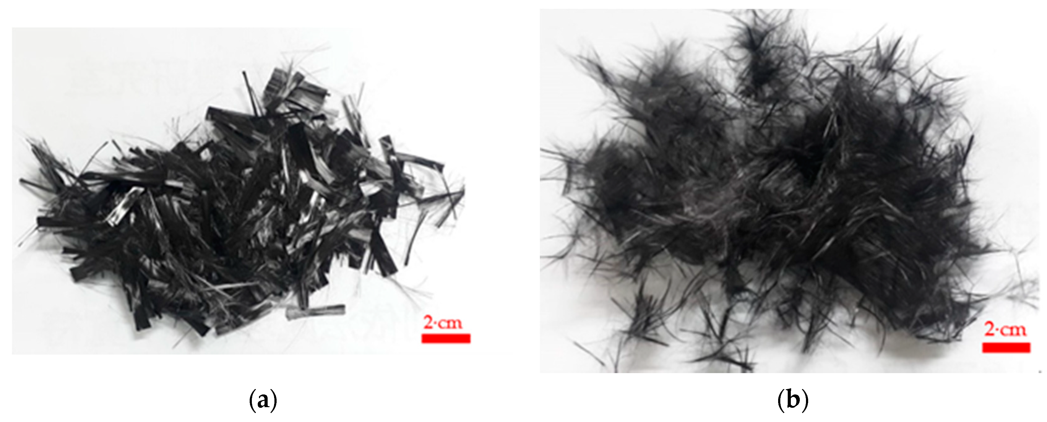
2.2. Carbon Fiber
Carbon fiber applications are exploited in the aerospace industry, automobile industry, and other fields, which have high specific strength and fatigue resistance. The short carbon fiber was acquired from Tairylan Division, Formosa Plastics Group, Taipei, Taiwan, R.O.C. [
30], and the properties are listed in
Table 2. PAN-based carbon fiber was included in the cement mixture, by the dispersion of linear strands; the fibers must be dispersed before mixing, to ensure that the fibers were evenly mixed into the cement base material. The chopped carbon fiber is caked during mixing because it has relatively high slenderness. The chopped carbon fiber’s appearance and pneumatic dispersion are shown in
Figure 1.
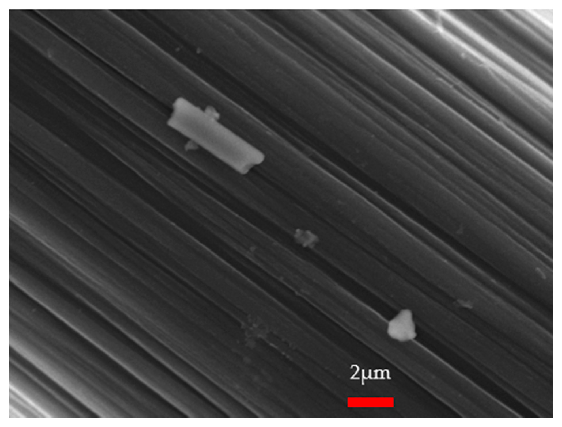
The carbon fiber surface microscopy was examined with a scanning electron microscope (model: JSM-7610F, JEOL, Tokyo, Japan), at the Department of Molecular Science and Engineer Lab, National Taipei University of Technology. The carbon-fiber-surface SEM observation is shown in
Figure 2, with a highly magnified image. The presence of silane on the surface of carbon fiber was observed in GC/MS testing [
21], as shown in
Figure 2. The silane on the surface of the chopped carbon fiber might interfere with the bonding strength between the carbon fiber and cement.
2.3. Carbon-Fiber-Reinforced Mortar (CFRM)
Fiber-reinforced mortar (FRM) presents high flexural deformation; it can increase durability, reduce shrinkage, and improve toughness. The carbon fiber can restrain mortar cracking and prevent fracture failure; it can also offer improvement to the mechanical and physical properties of mortar. In this study, the water–cement ratio of 0.4 was used in the CFRM specimens, and sand was 105% of the cement weight. The dispersed carbon fiber was mixed in the dry stage and then wet state, to aid in the uniform distribution in the mortar.
2.4. Carbon-Fiber-Reinforced Concrete (CFRC)
Generally, fibers are usually used in concrete, to control cracking due to plastic shrinkage and drying shrinkage. Some types of fibers could produce greater impact resistance, abrasion resistance, and shatter resistance in concrete. Since the modulus of elasticity of carbon fiber is higher than it is for the plain concrete, it can help the CFRC carry the load by increasing the tensile strength. To ensure that each fiber strand is effective, it is necessary to disperse the fibers uniformly in the concrete. In this study, the water–cement ratio of the CFRC was 0.45, and the sand weight was the same as the CFRM. As the component of a composite material that resists compressive stress, the aggregate was 225% of the cement weight. The fineness modulus of aggregates for CFRC specimen was 6.01, as shown in
Table 3.
3. Experimental Methods and Setups
A series of tests were conducted according to ASTM and ACI standards [
32,
33,
34], to investigate the effect of different lengths of carbon fibers (6, 12, and 24 mm) on the compressive strength, flexural strength, and impact energy of the CFRM and CFRC. The CFRC and the CFRM specimens were cured at 28 days. The CFRM and CFRC were tested by using a universal testing machine and free-fall impact equipment. The compressive and bending tests were conducted by using a universal testing machine (HT-9501 Series. Hong-Ta, Taipei, Taiwan), with a load cell (WF 17120, Wykeham Farrance, Milan, Italy), at the Department of Civil Engineering, National Taipei University of Technology. The experimental setup and the process of compression, bending, and impact tests are listed below.
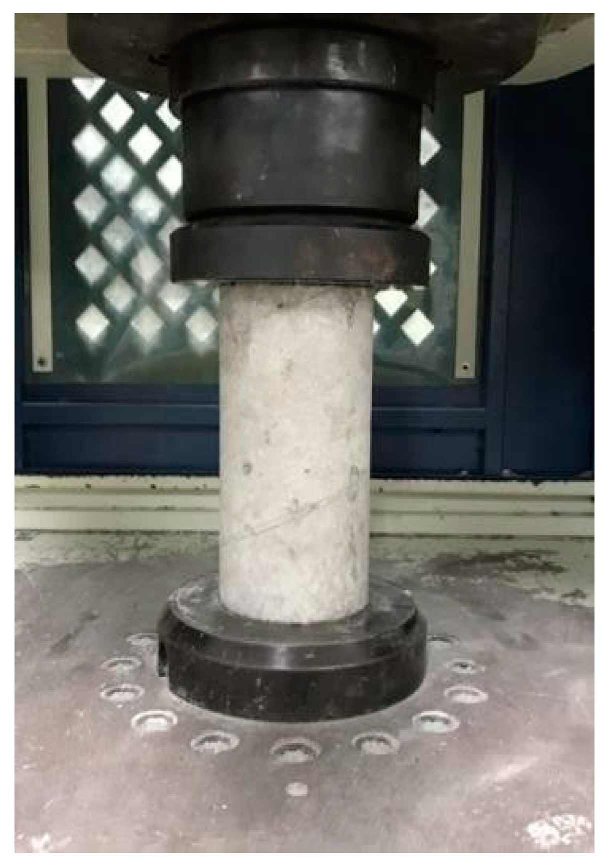
3.1. Compressive Test
The carbon-fiber-reinforced composites were tested under ASTM C39/C 39M-01 standards [
32]. The cylindrical specimen was placed in a universal testing machine with a loading rate of 900–1800 N/s (strain rate of 10
−6/s to 10
−4/s), which was acted on the flat surface of the specimen, and the dimension was ⌀10 cm × 20 cm [
32], respectively. The cylindrical specimen was tested under the material laboratory of the Department of Civil Engineering, National Taipei University of Technology, Taiwan.
Figure 3 shows the compression test experimental fixture of CFRC.
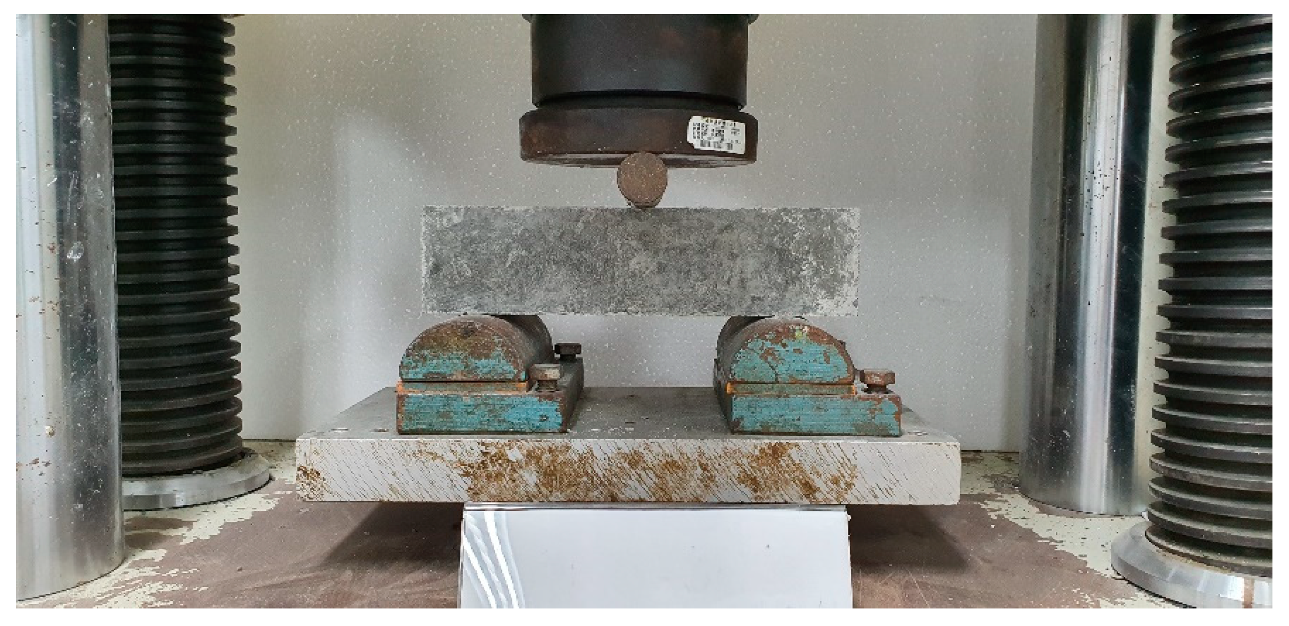
3.2. Three-Point Bending Test
According to ASTM C 293-02 [
33], the CFRM and CFRC specimens were tested with dimensions 28 cm × 7 cm × 7 cm [
33]. The chopped carbon fibers were distributed uniformly in mortar and concrete, after using the pneumatic method. The CFRM and CRFC were tested under a loading rate of 1.2 MPa/min, respectively.
Figure 4 shows the setup of the three-point bending test; the specimen’s flexural strength is determined in the universal testing machine.
3.3. Free-Fall Impact Test
The free-fall impact tests of CFRM and CFRC were conducted under ACI 544-2R [
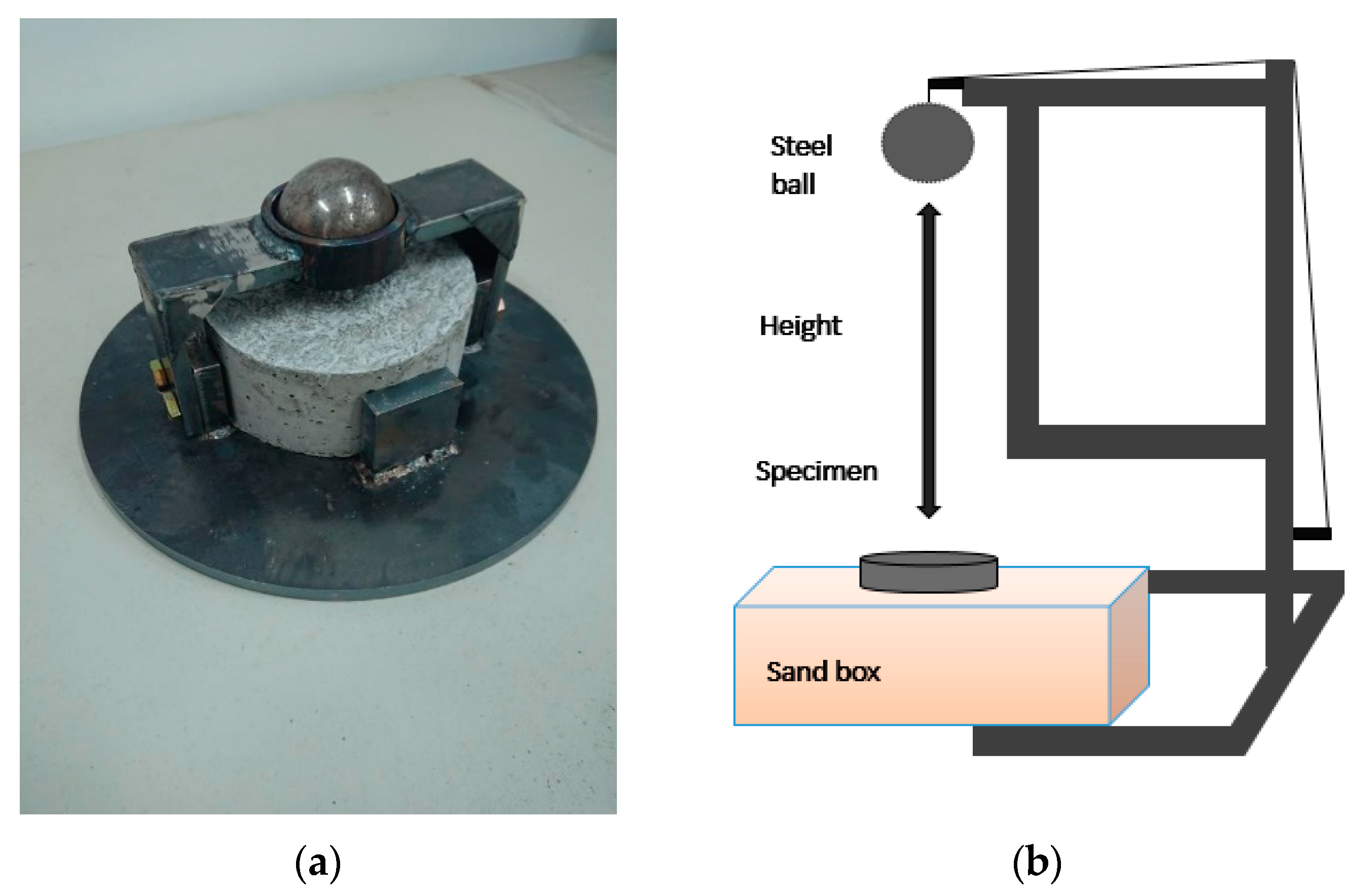
34]. The sieving dispersion was involved in the specimen preparation process. The given length and quantity of carbon fibers were mixed evenly in the dry cement. The dry-mixing process comprised the period of proper time, followed by wet mixing after adding the aggregates and water. The concrete and mortar cylindrical specimen’s dimensions were ⌀150 mm in diameter and 64 mm in thickness, and the specimens were placed in the sandbox, for impact-load performance. The specimens were tested with different impact energies, in the impact test, by using an iron ball at the heights of 100 to 500 cm.
Figure 5a shows the standard drop-weight-test cylindrical specimens and equipment, and the free-fall impact test setup is shown in
Figure 5b.
The CFRM and CFRC were tested with different impact energies; the string was used to hang the mass steel ball at a certain height. The CFRM and CFRC specimens’ surfaces resist a single impact at high energy and repeated impact at lower energy. The impact energy can be represented as follows.
In Equation (1), E is potential energy (J), m is mass (kg), g is gravity acceleration (m/s2), and h is height (m). The CFRC and CFRM are examined at different energies with a single and repeated free-fall impact test. The CFRC and CFRM with different lengths of fiber (6, 12, and 24 mm) possess better mechanical performance than the benchmark.
4. Results and Discussions
The disparate lengths of fiber 6, 12, and 24 mm were incorporated with cement, to prepare CFRM and CFRC specimens. The test results of compressive, bending, and impact performance were obtained with the different fiber lengths of carbon fiber in CFRM and CFRC specimens.
4.1. Compressive Test Results
In this subsection, the CFRM and CFRC compressive strengths were tested with different lengths of fiber and then compared with a benchmark specimen (without added carbon fiber). Each test group had three specimens.
4.1.1. Compressive Test Results of CFRM
Table 4 shows that the specimen name C-B-M represents the benchmark mortar specimen without carbon fiber; C-L6-M, C-L12-M, and C-L24-M represent CFRM adding 6, 12, and 24 mm chopped carbon fiber.
Table 4 shows the benchmark specimen’s compressive strength and CFRM with a disparate length of carbon fiber. The chopped carbon fibers using the pneumatic dispersion process facilitated a uniform distribution in the cement and contributed to enhancing the CFRM overall strength. The 6 mm chopped carbon fiber increases the compressive strength by 22.2%, on average (39.75 MPa), compared with the benchmark specimen, while 12 and 24 mm enhanced it by 14% and 11.3%, on average.
The strength of the CFRM is higher than that of the benchmark mortar specimen, and increasing compressive strength is dependent on the length of the carbon fiber. The chopped 6 mm carbon fibers were uniformly inhabited in the cylindrical specimens because the length of 6 mm fibers is shorter than the others, and it occupies more volume than the longer fiber in the concrete matrix with the same weight proportion. The compressive strength of CFRM specimen was increased by reducing the length of the carbon fiber.
4.1.2. Compressive Test Results of CFRC
In
Table 5, the specimen name C-B-C represents the benchmark concrete specimen without carbon fiber; C-L6-C, C-L12-C, and C-L24-C represent CFRC added with 6, 12, and 24 mm lengths of chopped carbon fibers.
Table 5 shows the compressive strength of the benchmark specimen and CFRC specimens with different carbon fiber lengths. The 6 mm length of CFRC increases resistances by 25.3%, on average, compared to the benchmark concrete. The 12 and 24 mm carbon fiber lengths increase the compressive strength by 14.4% and 4.4%, on average, respectively.
The C-L6-C chopped carbon-fiber-reinforced concrete has a maximum compressive strength than the benchmark and other fiber-reinforced concrete (such as C-L24-C and C-L12-C). Because the length of 6 mm fibers is shorter than the others, they possess more volume than the longer fibers in the concrete matrix with the same weight proportion; that is, 6 mm fiber occupies two times more space than the 12 mm carbon fibers, and four times more space than the 24 mm carbon fibers.
4.2. Three-Point Bending Test results
The chopped CFRM and CFRC increase their flexural strength, compared to the standard benchmark specimens. In this subsection, the flexural strength of CFRM and CFRC with different lengths of fiber are compared with the benchmark specimens (without added carbon fiber). The flexural strength of fiber-reinforced mortar and concrete is discussed below. Each test group has three specimens.
4.2.1. Three-Point Bending Test Results of CFRM
As shown in
Table 6, the 24 mm chopped CFRM (F-L24-M) increases its flexural strength up to 42.14% more than the flexural strength of the benchmark specimen. Similarly, the flexural strength of CFRM with 6 and 12 mm lengths of carbon fibers has higher strength than the benchmark specimen (24.57% and 29.06%, respectively). The flexural strength of CFRM is increased with the increasing length of the fiber.
From the above test results, we can see that the length of the long carbon fiber (24 mm) enhances its maximum strength in the CFRM. This is because the longer carbon fiber can resist tensile force, and its failure mode is fracture failure instead of slip failure (see
Section 4.4, “Optical Microscopic Observation”).
4.2.2. Three-Point Bending Test Results of CFRC
Table 7 shows that the CFRC specimens with the length of 6, 12, and 24 mm carbon fibers increase their flexural strength, compared with the benchmark specimen (F-B-C), by 17.82%, 22.92%, and 27.07%, respectively. The flexural strength of CFRC is increased by increasing the length of the chopped carbon fiber.
As seen from
Table 6 and
Table 7, the average flexural strength of CFRC is less than the average flexural strength of the CFRM at the same length of chopped carbon fiber.
4.3. Free-Fall Impact Test Results
A steel ball was fixed at a given height and repeatedly impacted the top surface of the specimens, as shown in
Figure 5b. The number of impacts under different impact energies was recorded. Each test group has five specimens.
4.3.1. Free-Fall Impact Test of CFRM
The impact numbers of benchmark and CFRM specimens under different impact energies are shown in
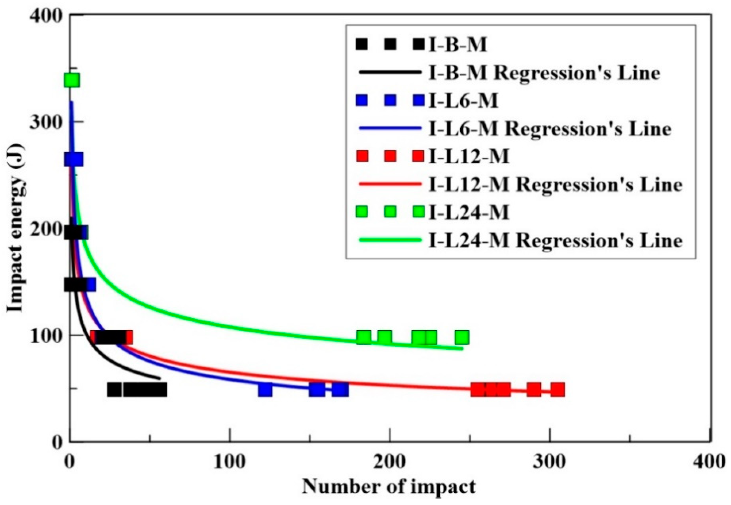
Table 8. It was observed that the longer carbon fiber could resist more impacts at lower impact energies. For instance, under 98 J impact energy, the maximum number of impacts at the failure of CFRM specimens with the length of 24, 12, and 6 mm carbon fiber were 245, 35, and 31, respectively. The 24 mm CFRM resists repeated impact and exhibits higher effectiveness; it also attained more than 2000 impact numbers under 49 J. The one-time impact failure energy of 24 mm carbon-fiber-reinforced concrete was 339 J, which is much larger than the benchmark mortar specimen.
Generally, the longer fiber has better impact resistance.
Table 8 shows that the impact resistance is predicted under repeated loading with an impact energy of 98 and 49 J. However, the impact resistance under high impact energy is relatively difficult to assess. This is because the impactor was sometimes dropped on the surface of either the gravel or fiber during the test, causing the impact number to be unstable when the steel lump hits the specimens at high impact energy.
The relationships of the number of impacts and impact energy of CFRM are shown in
Figure 6. As seen from
Figure 6, the impact resistance (impact energy and impact number at failure) of CFRM specimens was higher than that of the benchmark.
4.3.2. Free-Fall Impact Test of CFRC
The impact numbers of benchmark and carbon-fiber-reinforced concrete specimens under different impact energies are shown in
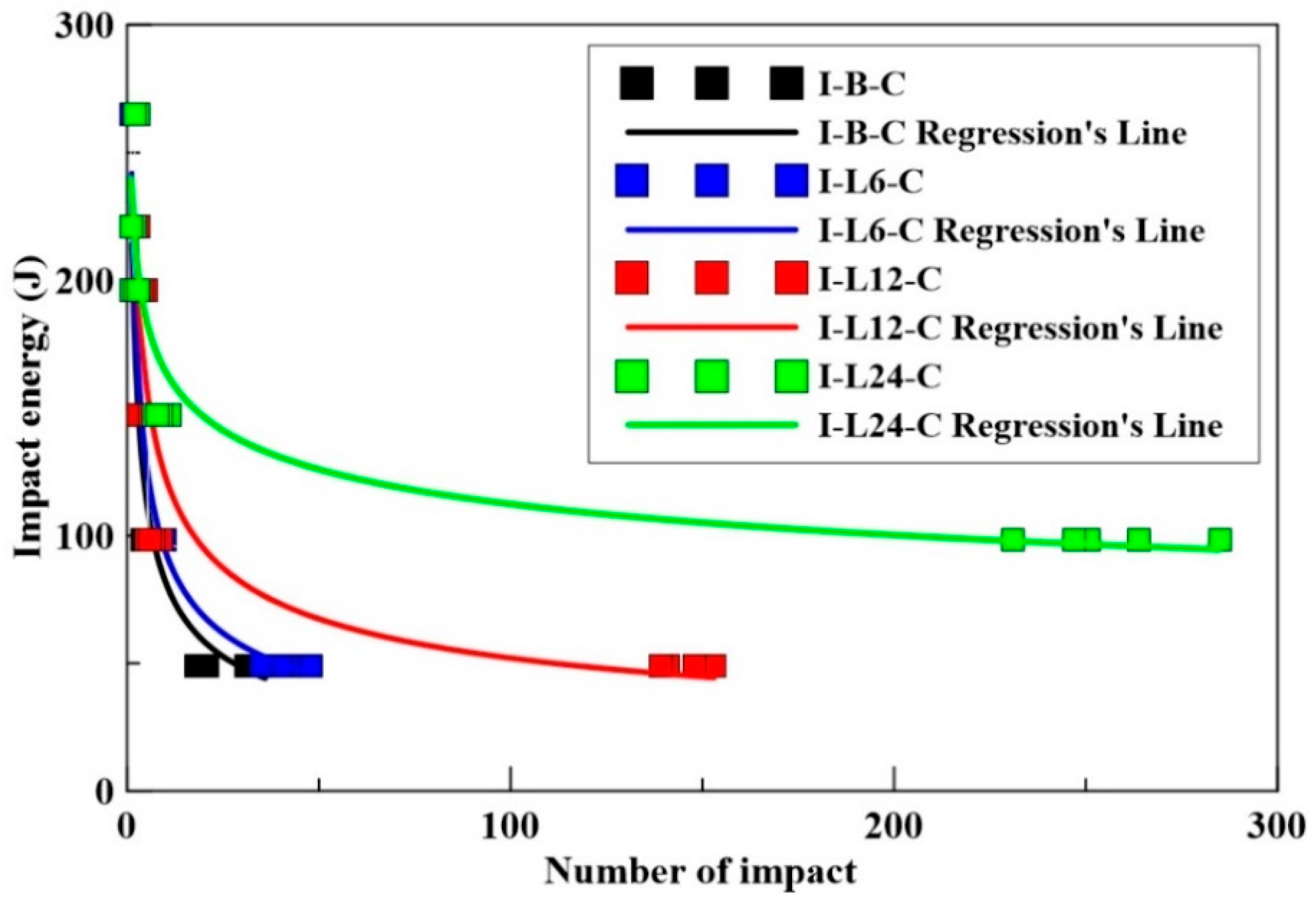
Table 9. From the impact test results, we can see that the CFRC specimen’s failure was not caused by the accumulation of energy. For instance, under 147 J impact energy, the maximum impact numbers at the failure of CFRC specimens with the length of 6, 12, and 24 mm carbon fibers were 4, 6, and 11, respectively. Moreover, under 49 J impact energy, the maximum impact numbers at the failure of CFRC specimens with the length of 6, 12, and 24 mm carbon fibers were 48, 153, and ≥2000, respectively. It is worth mentioning that, under 49 J impact energy, the 24 mm CFRC maximum number of impacts before failure was more than 2000 times. The 24 mm carbon fiber length in CFRC has better impact resistance at lower impact energies. As seen in
Table 9, the impactor with high impact energy sometimes hits the surface of gravels or fibers. The increased impact resistance can be captured merely under the repeated loading of 98 and 49 J.
The impact energy/number relationship of benchmark and CFRC specimens is shown in
Figure 7. As seen in
Figure 7, the CFRC with 24 mm carbon fiber (I-L24-C) specimen has a maximum impact energy resistance, as compared with the benchmark and other CFRC (I-L6-C, and I-L12-C).
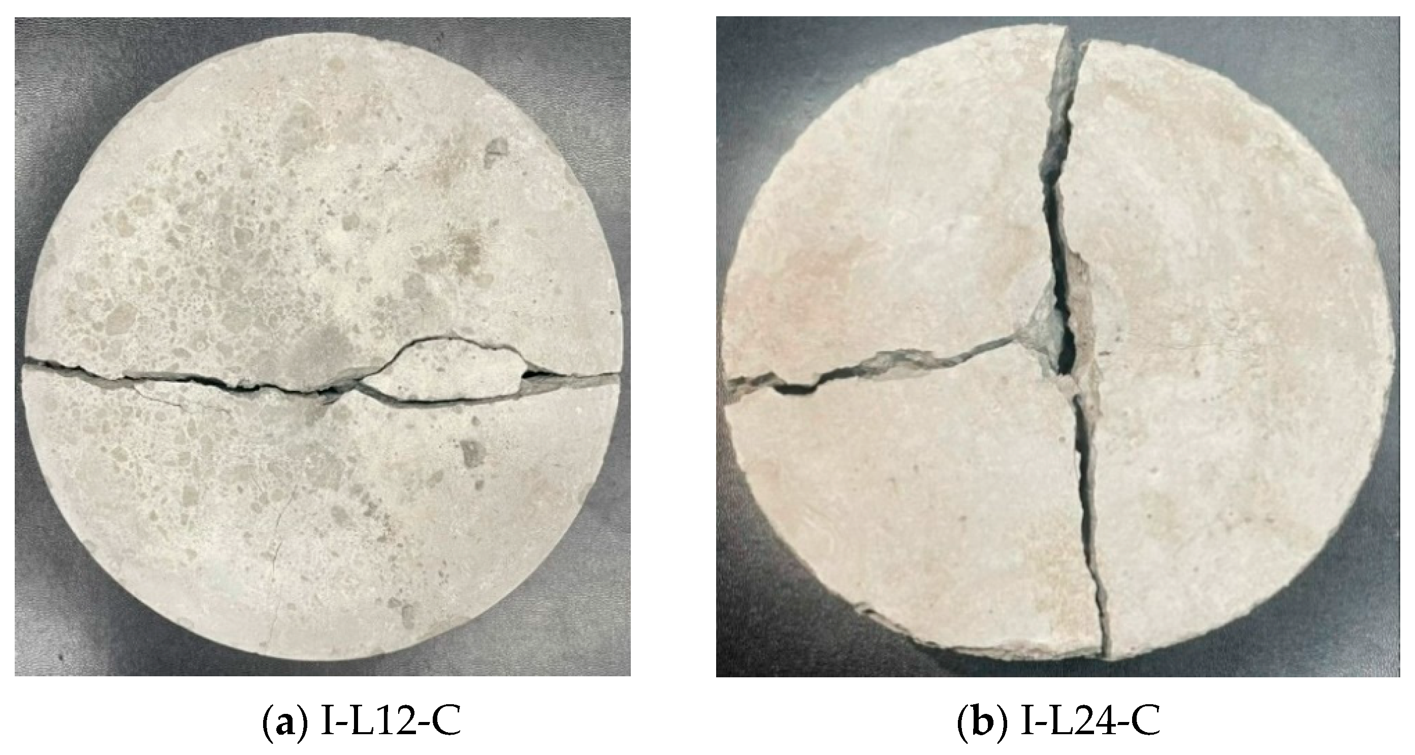
Figure 8 shows the failure image of specimen I-L12-C in two pieces and I-L24-C, in three pieces, under repeated impact.
4.4. Optical Microscopic Observation
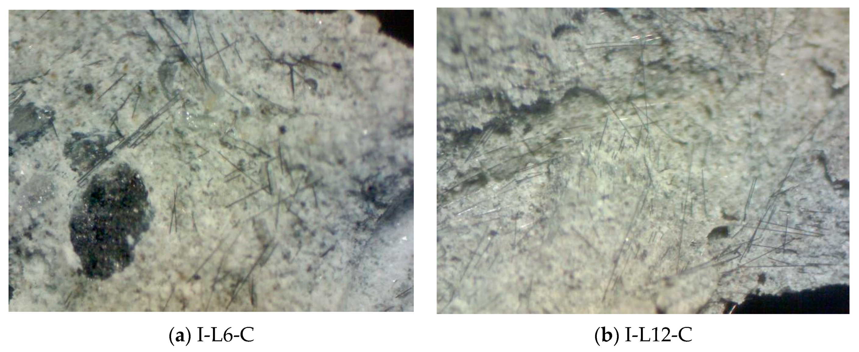
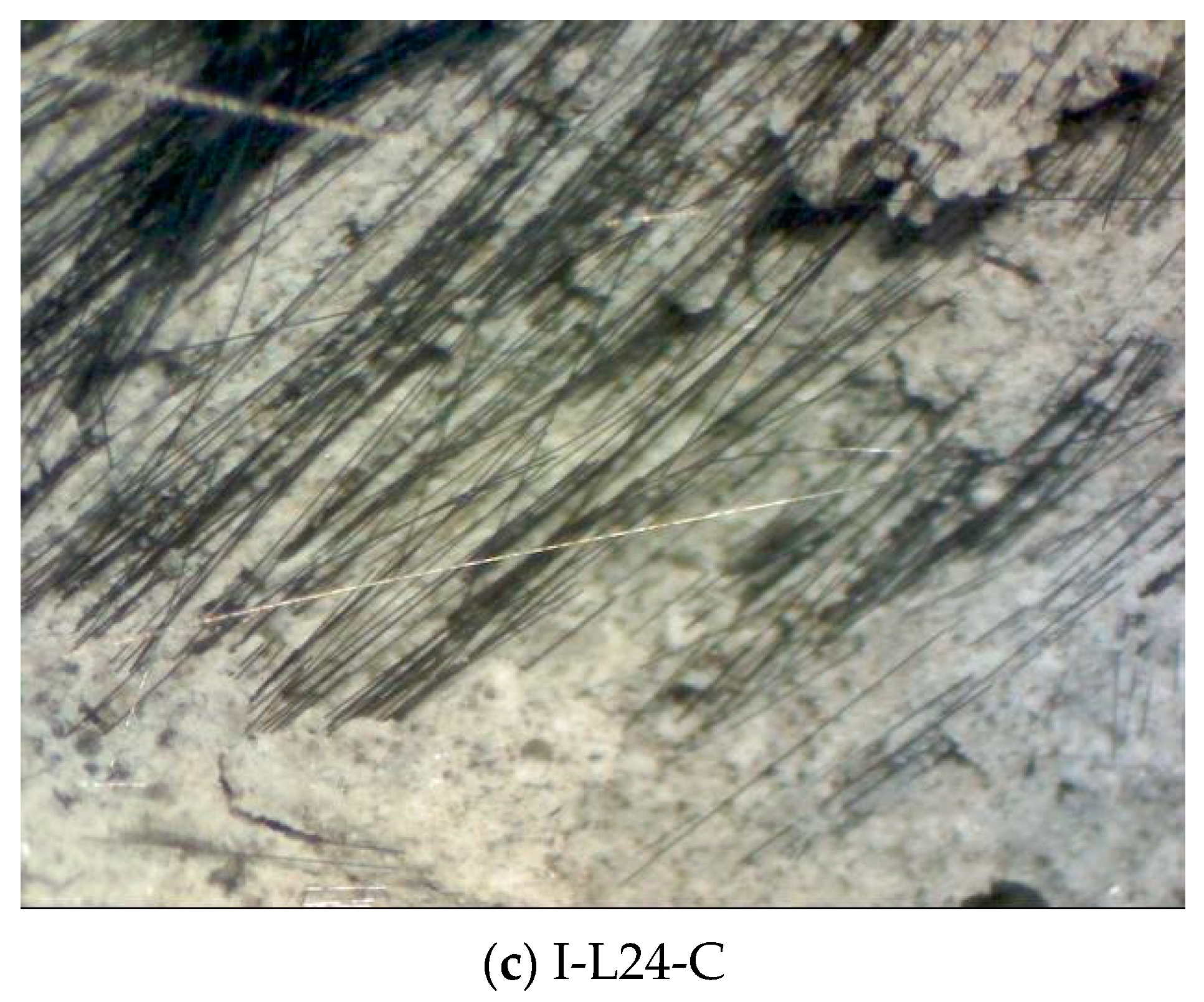
After the impact test, the failure surfaces of the CFRC specimens were analyzed by optical microscopy (model: MSH631-B, Hamlet, New Taipei City, Taiwan), with a high magnification range between 200 and 400, at the material laboratory of the Institute of Mineral Resources Engineering, National Taipei University of Technology.
Figure 9 shows the photomicrograph of the fractured surface of the CFRC specimens. The CFRC surface shows that the fiber is well dispersed and uniformly distributed in the concrete, because each of the linear strands of fiber can be seen in the photo.
The CFRC fracture surface from the photomicrograph is obtained from an optical microscope, as shown in
Figure 9, which shows that the I-L6-C specimen contribution with reinforced concrete is less effective than the I-L12-C and I-L24-C specimens. Because the fibers in I-L6-C mostly occur as slippage failure, while I-L12-C and I-L24-C had more rupture failure instead of slippage failure. The slippage and rupture failure occurred when the strength was increased with the increasing length of fiber in the impact-test specimen.
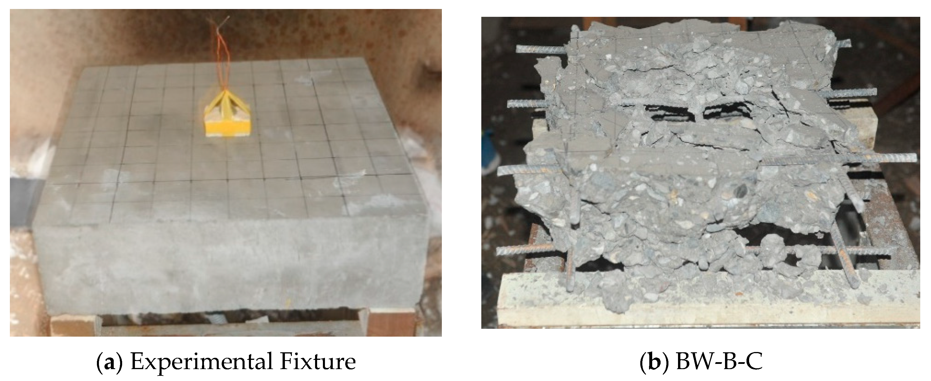
5. Blast Wave Explosion Test Verification
The blast wave explosion test was used to verify the anti-blast wave resistance of different carbon fiber lengths of CFRC. In
Table 10, the specimen BW-B-C represents the benchmark specimen, which had no added carbon fiber. Specimen BW-L12-C and specimen BW-L24-C represent CFRC with 12 and 24 mm chopped carbon fiber added.
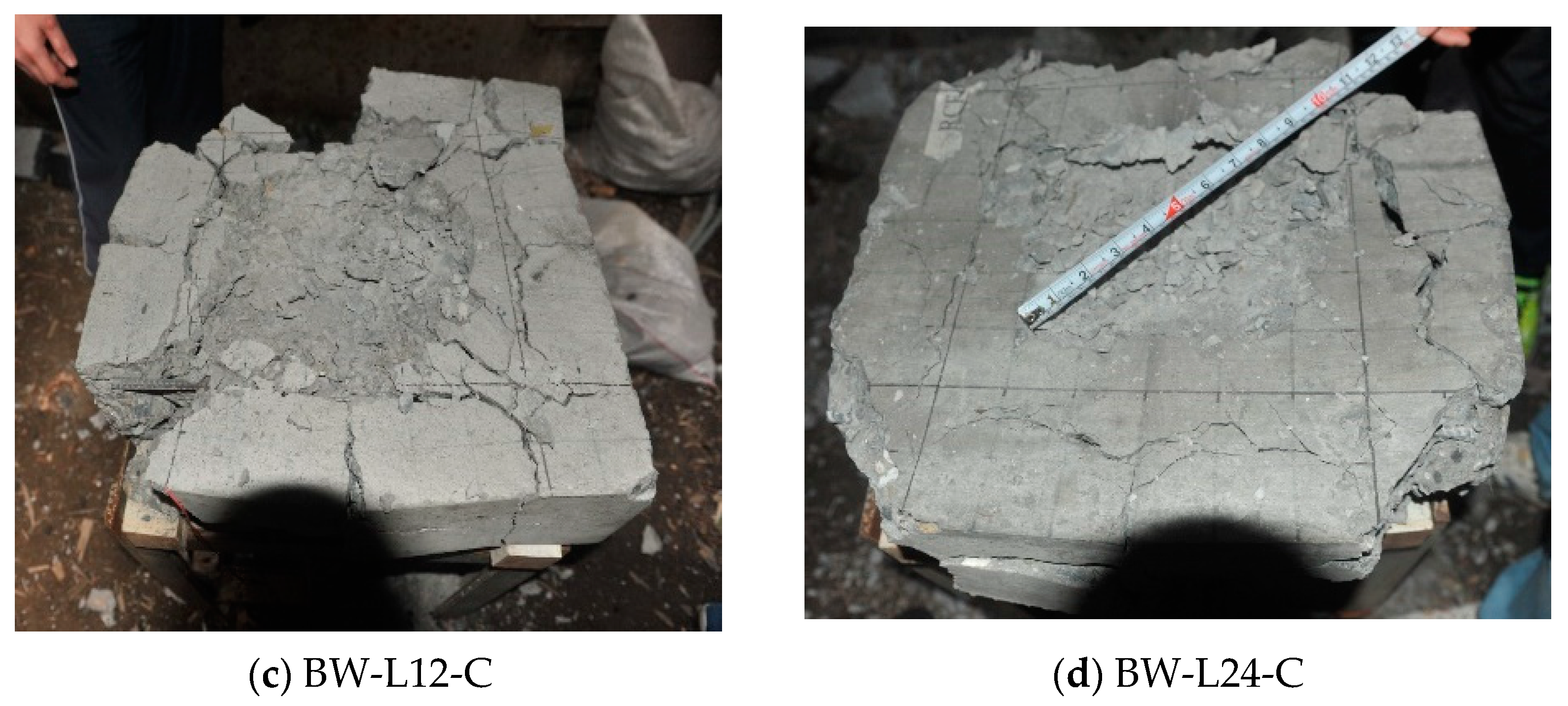
Figure 10a shows that the dynamite C4 (150 g) is placed on the top surface of a CFRC slab, to demonstrate the blast-wave resistance of chopped fiber reinforcement.
Figure 10b shows the failure mode of an ordinary reinforced concrete slab specimen (without carbon fiber), the shock wave caused by the explosion, and the specimen completely crushed.
Figure 10c shows specimen BW-L12-C after the explosion; an obvious crater can be observed on the slab’s top surface. Moreover,
Figure 10d shows the post-test photograph of specimen BW-L24-C; minor spall damage is observed at the rear side of the slab, indicating tensile strength improvement.
Table 10 shows the failure mode, damage diameter, and depth of CFRC specimens after the blast wave explosion. The specimen BW-B-C shows breaching failure, and the specimens BW-L12-C and BW-L24-C both present spalling failure. The spalling depth of specimen BW-L12-C is 5 cm, and the inner/outer circle diameters of the spalling surface are 36 and 50 cm, respectively. Similarly, the spalling depth of specimen BW-L24-C is 4.3 cm, and the inner/outer circle diameters of the spalling surface are 31 and 35 cm. The blast-wave-explosion test result shows that the specimen BW-L24-C has better anti-blast performance than other specimens.


 ,
, 


