
Fibre Bragg Grating Based Acoustic Emission Measurement System for Structural Health Monitoring Applications


Abstract
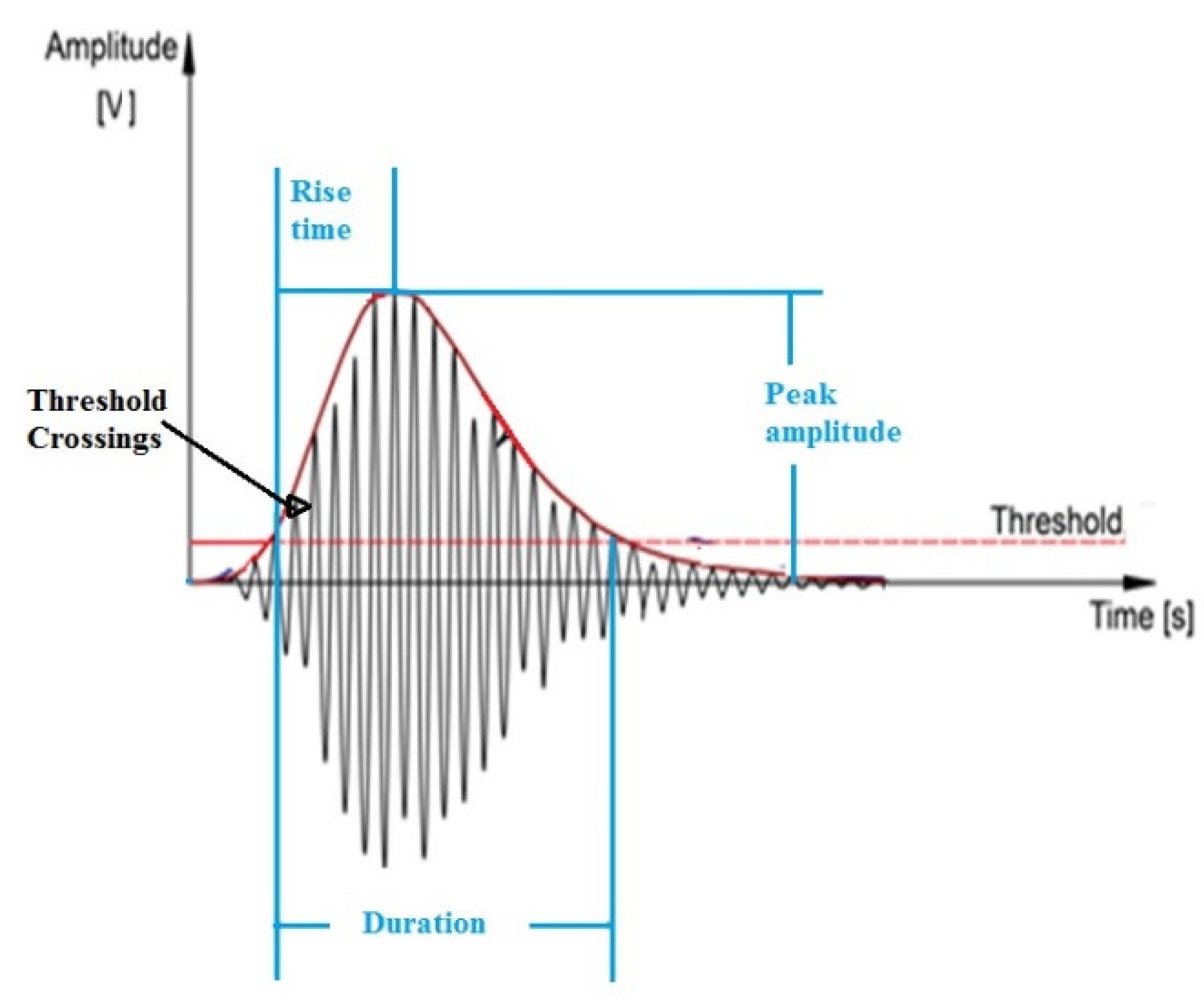
1. Introduction
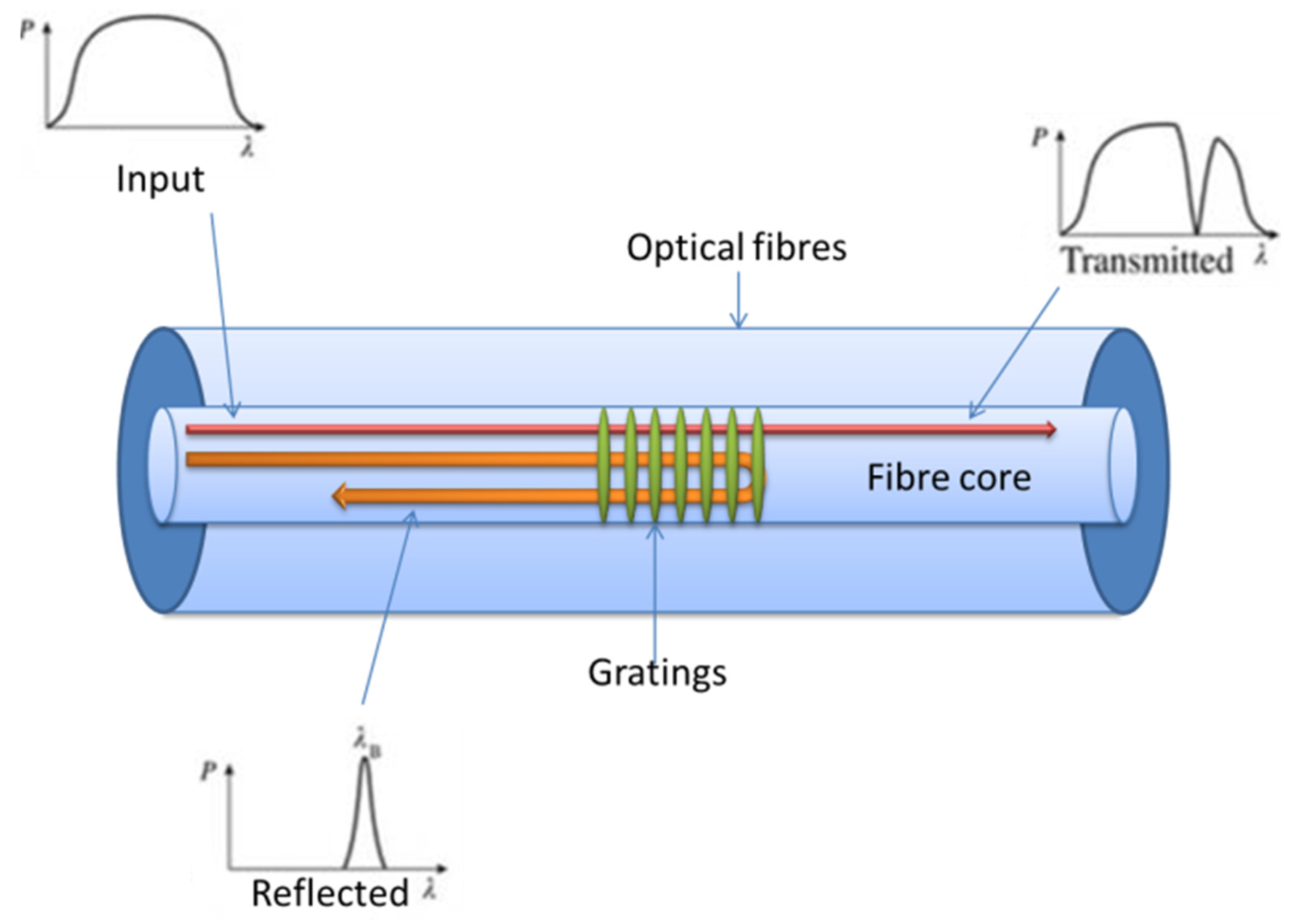
2. Fibre Bragg Gratings and Interrogation Systems
3. FBG Interrogation Systems for AE Monitoring
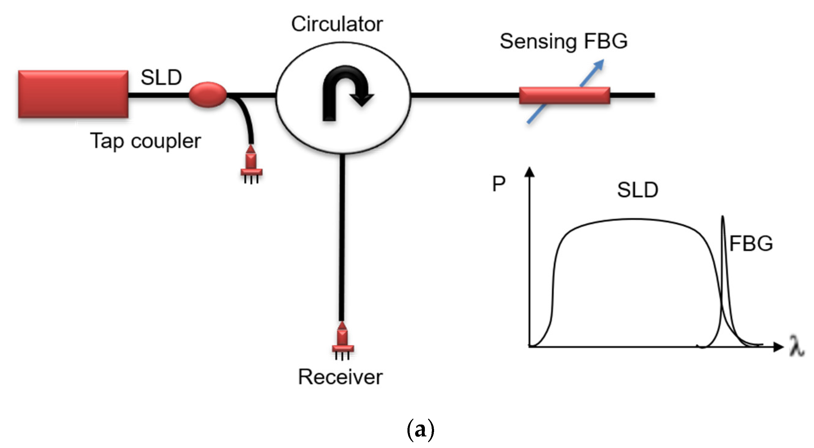
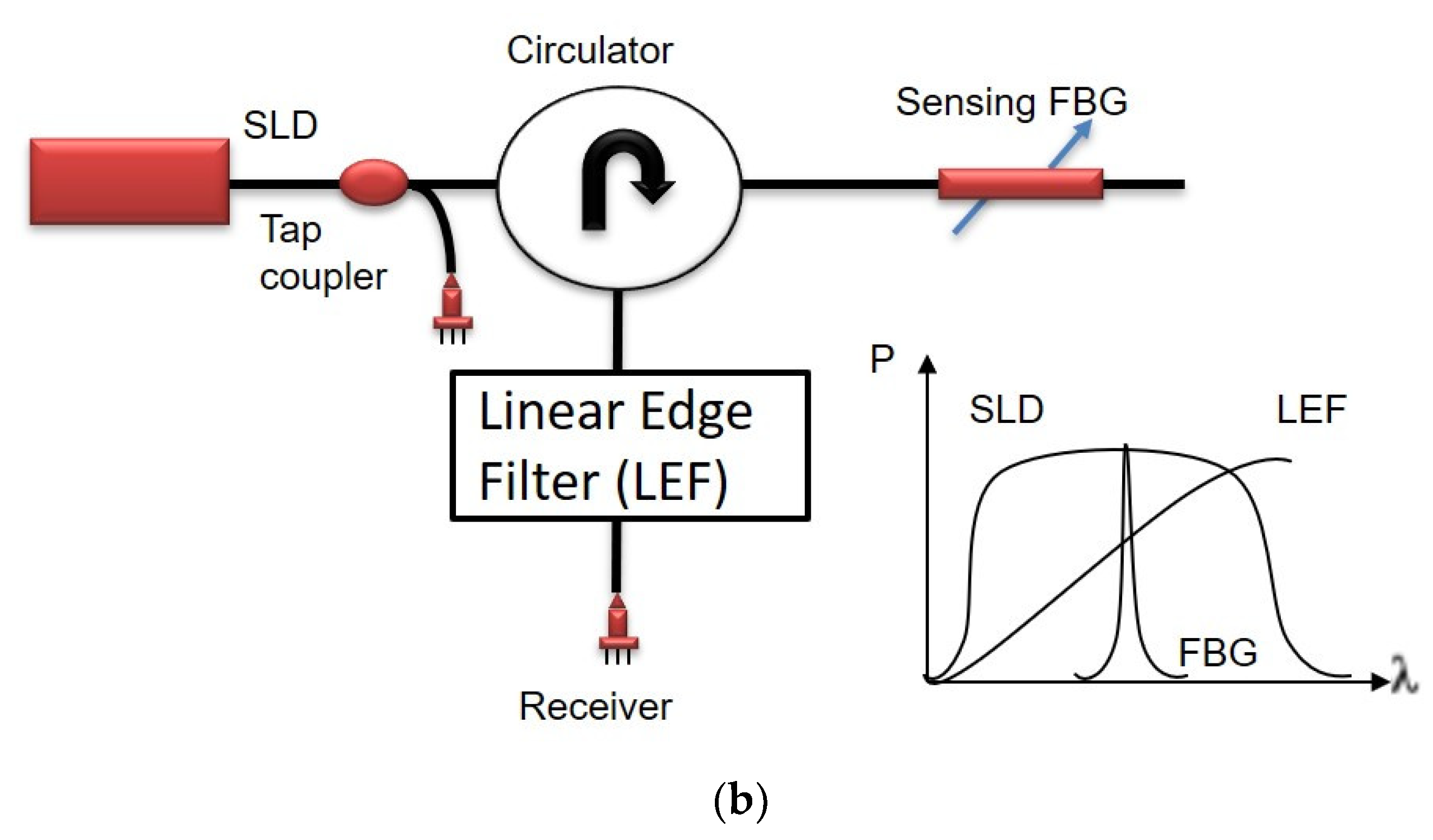
3.1. Power Detection and Edge Filter Detection Methods
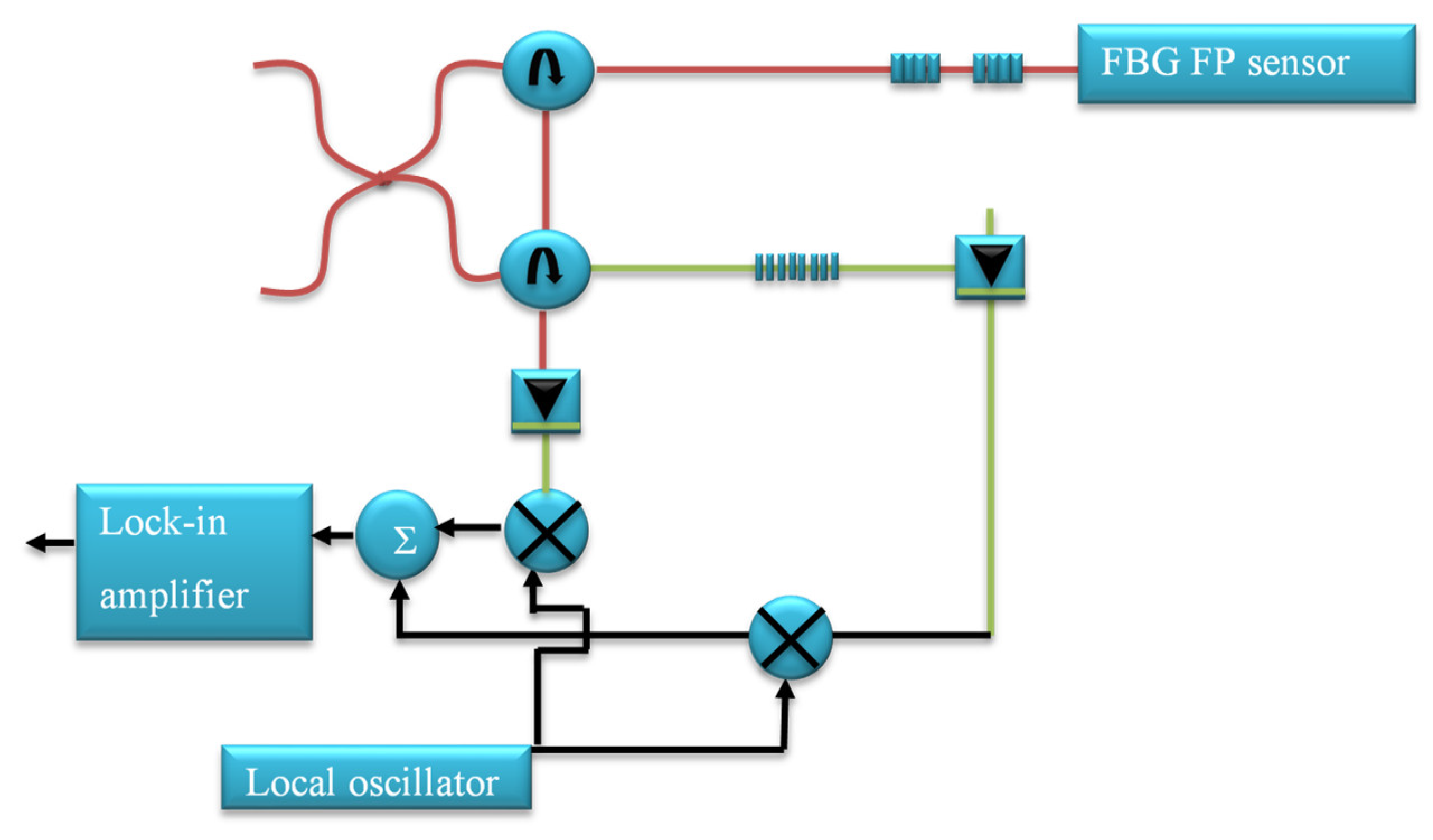
3.2. AE Detection Using an Optical Fibre Based F-P Sensor and Quadrature Recombination Technique
3.3. FBG AE Sensors by Altering the Gratings and Physical Configuration
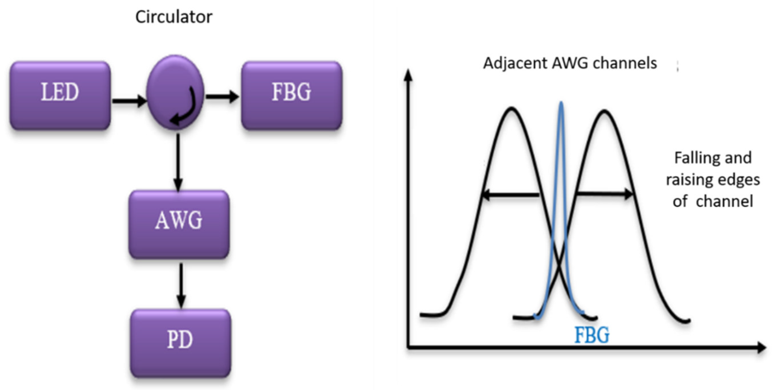
3.4. Spectrometric FBG AE and Ultrasonic Interrogation Systems
3.5. Bragg Grating-Based Laser Sensor System with Interferometric Interrogation and WDM
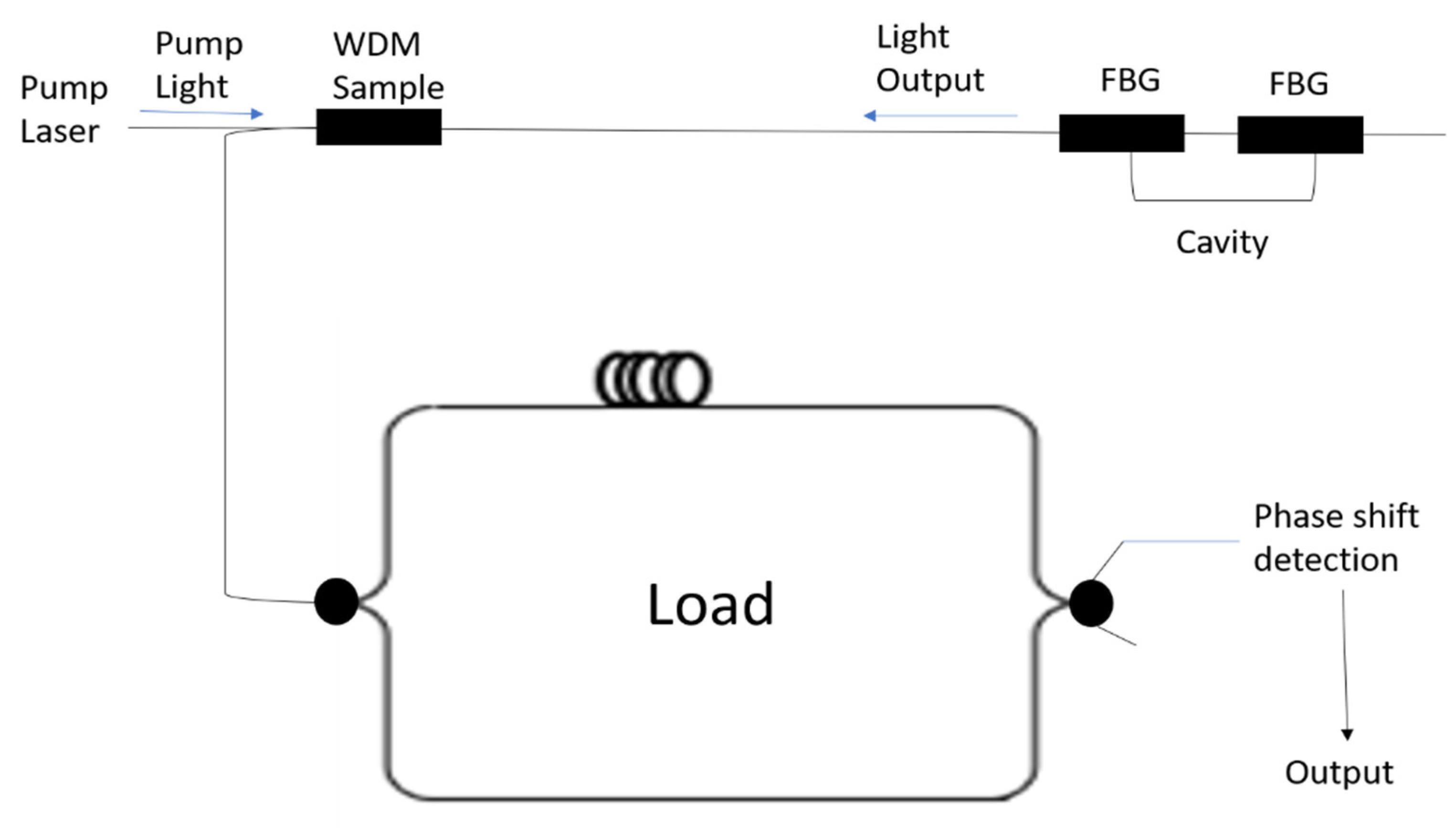
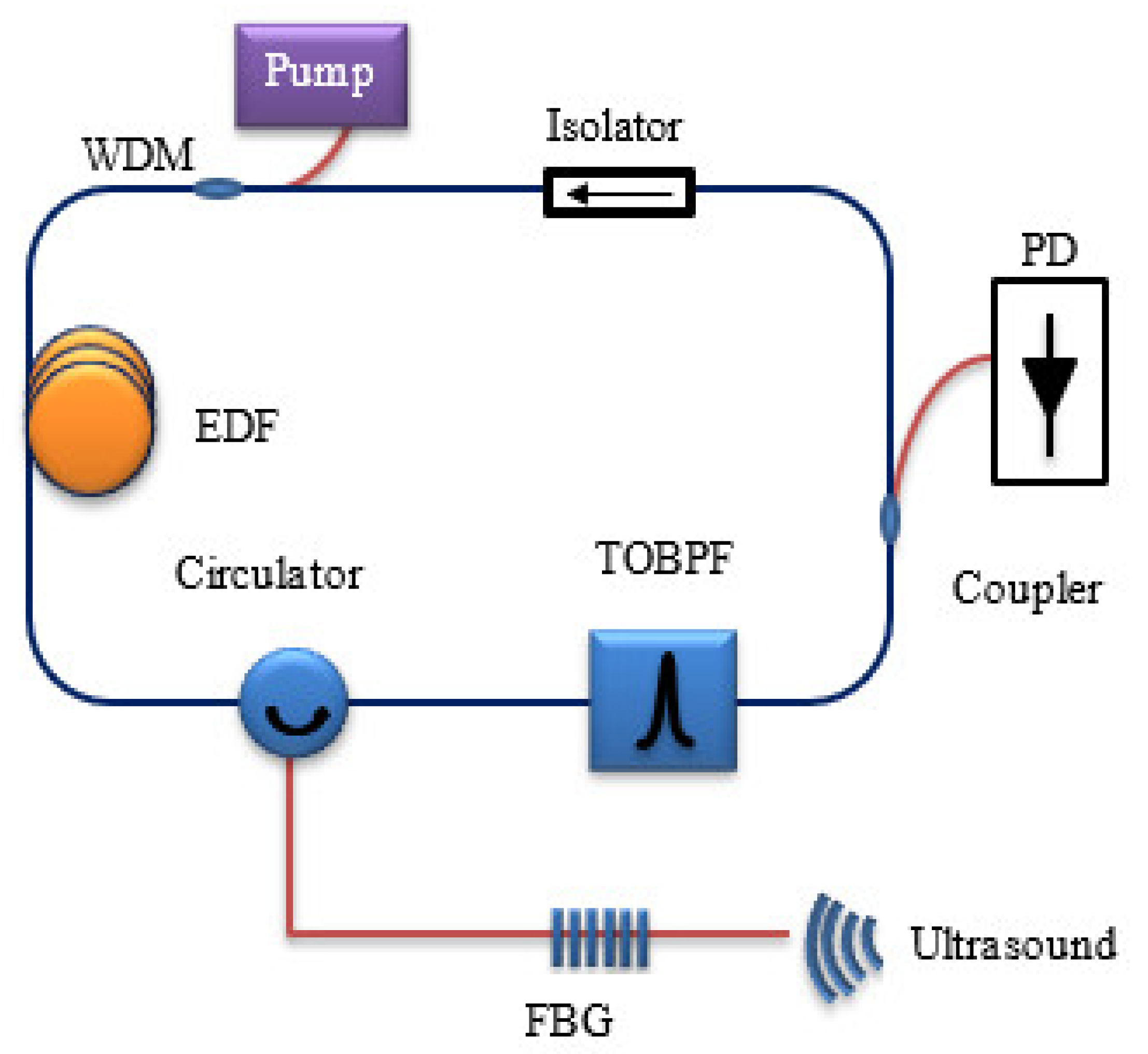
3.6. Intensity Demodulation Fibre Ring Laser Sensor System for AE Detection
4. Commercial FBG AE Interrogation Systems
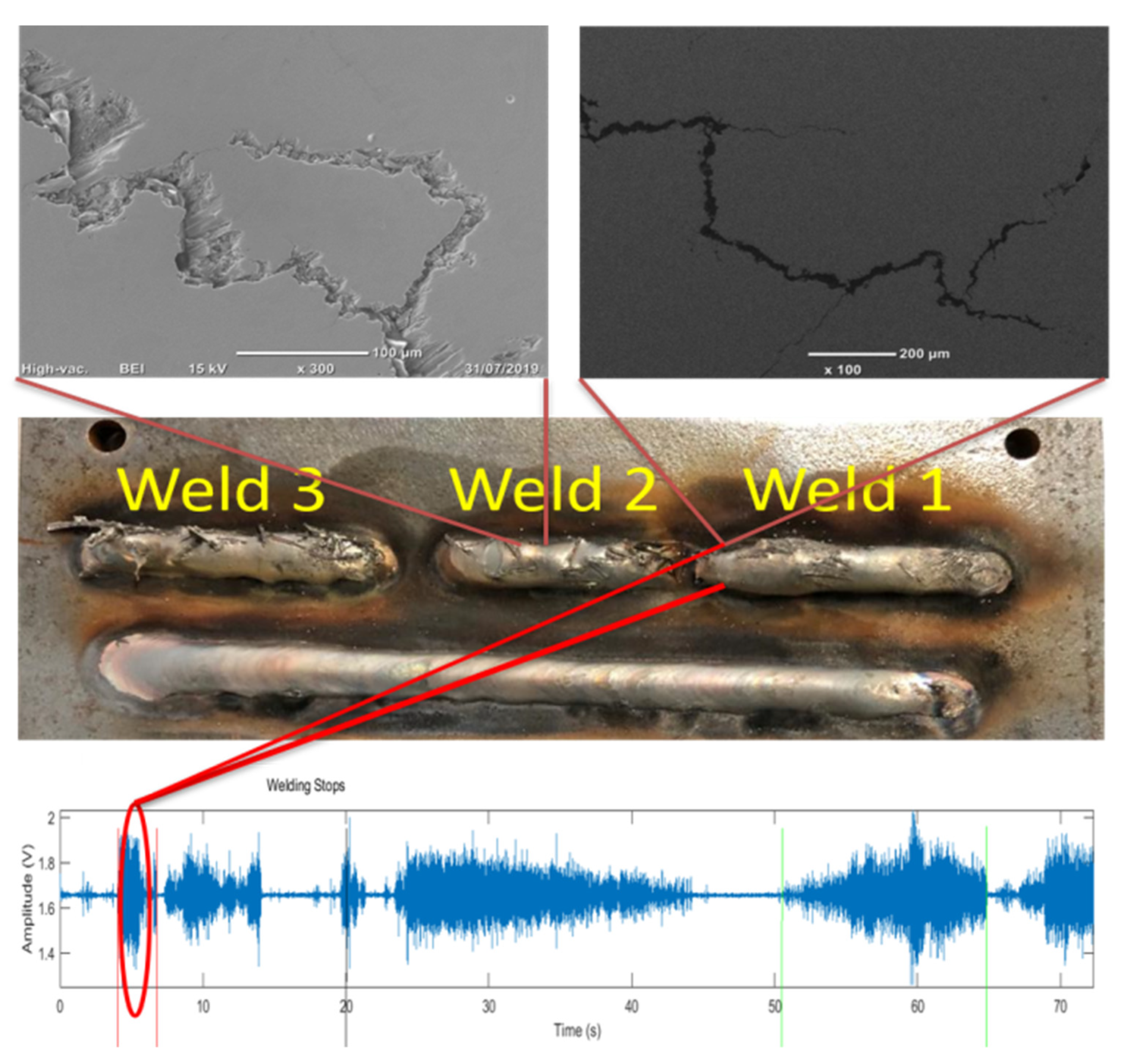
5. Application of FBG-Based AE Monitoring System and Its Market Potential
6. Conclusions
Author Contributions
Funding
Data Availability Statement
Conflicts of Interest
References
- Ellingwood, B.R. Risk-informed condition assessment of civil infrastructure: State of practice and research issues. Struct. Infrastruct. Eng. 2005, 1, 7–18. [Google Scholar] [CrossRef]
- Biondini, F.; Frangopol, D.M. Life-cycle performance of deteriorating structural systems under uncertainty: Review. J. Struct. Eng. 2016, 142, F4016001. [Google Scholar] [CrossRef]
- Nguyen, A.; Kodikara, A.T.L.; Chan, H.T.; Thambirathnam, D. Deterioration assessment of buildings using an improved hybrid model updating approach and long-term health monitoring data. Struct. Health Monit. 2018, 18, 5–19. [Google Scholar] [CrossRef]
- Yapar, O.; Basu, P.K.; Volgyesib, P. Structural health monitoring of bridges with piezoelectric AE sensors. Eng. Fail. Anal. 2015, 56, 150–169. [Google Scholar] [CrossRef]
- Wiesław, M.O.; Tomaz, W.; Paweł, H.M. Structural Health Monitoring Methods for Composite Material. In Structural Health Monitoring of Composite Structures Using Fiber Optic Methods, 1st ed.; Rajan, G., Prusty, G., Eds.; CRC Press: Boca Raton, FL, USA, 2016; pp. 21–40. [Google Scholar]
- Raj, B.; Jayaykumar, T.; Rao, B.P.C. Non destructive testing and evaluation for structural integrity. Sadhana 1995, 20, 5–38. [Google Scholar] [CrossRef]
- Dhale, A.; Khan, F. Application of Acoustic Emission Technique in Various Field. Int. J. Eng. Res. 2013, 7, 80–85. [Google Scholar]
- Huang, M.; Jiang, L.; Liaw, P.K.; Brooks, C.R.; Seeley, R.; Klarstrom, D.L. Using Acoustic Emission in Fatigue and Fracture Materials Research. JOM 1998, 50, 1–14. [Google Scholar]
- Moriyama, T.; Misaki, T. Measuring method using PZT sensor for mass flow of moved bed gravity flow. SICE 1995, 1191–1195. [Google Scholar]
- Islam, M.R.; Ali, M.M.; Lai, M.H.; Lim, K.S.; Ahmed, H. Chronology of Fabry-Perot Interferometer Fiber-Optic Sensors and Their Applications a Review. Sensors 2014, 14, 7451–7488. [Google Scholar] [CrossRef]
- Por, G.; Doszpod, L.; Dobjan, T. Developing an Acoustic Emission Measuring System Based on Modular High Speed Data Acquisition. In Proceedings of the 30th European Conference on Acoustic Emission Testing &7th International Conference on Acoustic Emission, Granada, Spain, 12–15 September 2012. [Google Scholar]
- Kersey, A.D.; Davis, M.A.; Patrick, H.J.; Leblanc, M.; Koo, K.P.; Askins, C.G.; Putnam, M.A.; Friebele, J. Fiber Grating Sensors. J. Lightwave Technol. 1997, 15, 1442–1463. [Google Scholar] [CrossRef]
- Mihailov, S.J. Fibre Bragg Grating Sensors for Harsh Environments. Sensors 2012, 12, 1898–1918. [Google Scholar] [CrossRef]
- Regtien, P.P.L. Piezoelectric Sensors. In Sensors for Mechatronics; Elsevier: Amsterdam, The Netherlands, 2012; pp. 219–239. [Google Scholar]
- Presas, B.A.; Luo, Y.; Wang, Z.; Valentin, D.; Egusquiza, M. A Review of PZT Patches Applications in Submerged Systems. Sensors 2018, 18, 2251. [Google Scholar] [CrossRef]
- Zhu, Y.K.; Tian, G.Y.; Lu, R.S.; Zhang, H. A review of optical NDT technologies. Sensors 2011, 11, 7773–7798. [Google Scholar] [CrossRef]
- Di Sante, R. Fibre Optic Sensors for Structural Health Monitoring of Aircraft Composite Structures: Recent Advances and Applications. Sensors 2015, 15, 18666–18713. [Google Scholar] [CrossRef] [PubMed]
- Li, H.N.; Li, D.S.; Song, G.B. Recent applications of fibre optic sensors to health monitoring in civil engineering. Eng. Struct. 2004, 26, 1647–1657. [Google Scholar] [CrossRef]
- Minakuchi, S.; Takeda, N. Recent advancement in optical fiber sensing for aerospace composite structures. Photonic Sens. 2013, 3, 345–354. [Google Scholar] [CrossRef]
- Ajo-Franklin, J.B.; Dou, S.; Lindsey, N.J.; Monga, I.; Tracy, C.; Robertson, M.; Tribaldos, V.R.; Ulrich, C.; Freifeld, B.; Daley, T.; et al. Distributed Acoustic Sensing Using Dark Fiber for Near-Surface Characterization and Broadband Seismic Event Detection. Sci. Rep. 2019, 9, 1328. [Google Scholar] [CrossRef]
- Wang, Y.; Yuan, H.; Liu, X.; Bai, Q.; Zhang, H.; Gao, Y.; Jin, B.A. Comprehensive Study of Optical Fiber Acoustic Sensing. IEEE Access 2019, 7, 85821–85837. [Google Scholar] [CrossRef]
- Fu, T.; Wei, P.; Han, X.; Liu, Q. Application of Fiber Bragg Grating Acoustic Emission Sensors in Thin Polymer-Bonded Explosives. Sensors 2018, 18, 3778. [Google Scholar] [CrossRef]
- Wei, P.; Han, X.L.; Xia, D. A Measurement Method for the Velocity of Acoustic Emission Wave in Liquid Nitrogen. IEEE Trans. Ind. Electron. 2018, 65, 8232–8238. [Google Scholar] [CrossRef]
- De Oliveira, R.; Ramos, C.A.; Marques, A.T. Health monitoring of composite structures by embedded FBG and interferometric Fabry–Perot sensors. Comput. Struct. 2008, 86, 340–346. [Google Scholar] [CrossRef]
- Liao, H.; Lu, P.; Liu, L.; Wang, S.; Ni, W.; Fu, X. Phase demodulation of short-cavity Fabry–Perot interferometric acoustic sensors with two wavelengths. IEEE Photon. J. 2017, 9, 4808–4816. [Google Scholar] [CrossRef]
- Chen, R.; Theobald, P.; Gower, M. A novel fibre optic ring acoustic emission sensor. In Proceedings of the SPIE, Diego, CA, USA, 10–14 August 2008; pp. 1–12. [Google Scholar]
- Li, W.; Xu, C.; Ho, S.C.M.; Wang, B.; Song, G. Monitoring Concrete Deterioration Due to Reinforcement Corrosion by Integrating Acoustic Emission and FBG Strain Measurements. Sensors 2017, 17, 657. [Google Scholar] [CrossRef] [PubMed]
- Wu, Q.; Okabe, Y. High-sensitivity ultrasonic phase-shifted fiber Bragg grating balanced sensing system. Opt. Express 2012, 20, 28353–28362. [Google Scholar] [CrossRef] [PubMed]
- Perez, I.M.; Cui, H.L.; Udd, E. Acoustic emission detection using fiber Bragg gratings. In Proceedings of the SPIE—Smart Structures and Materials, Newport Beach, CA, USA, 6 August 2001; Volume 4328, pp. 209–235. [Google Scholar]
- Wu, Q.; Yu, F.; Okabe, Y.; Saito, K.; Kobayashi, S. Acoustic emission detection and position identification of transverse cracks in carbon fiber–reinforced plastic laminates by using a novel optical fiber ultrasonic sensing system. Struct. Health Monit. 2015, 14, 205–213. [Google Scholar] [CrossRef]
- Ye, Q.; Wang, Q.; Zhao, H.; Chen, J.; Wang, Y. Review of composite structural health monitoring based on fibre Bragg grating sensing principle. J. Shanghai Jiatong Univ. (Sci.) 2013, 2, 129–139. [Google Scholar]
- Hill, K.O.; Meltz, G. Fiber Bragg grating technology fundamentals and overview. J. Lightwave Technol. 1997, 15, 1263–1276. [Google Scholar] [CrossRef]
- Krishnaswami, S.; Fomitchov, P. Response of a fibre Bragg grating ultrasonic sensor. Opt. Eng. 2003, 42, 956. [Google Scholar]
- Ramakrishnan, M.; Rajan, G.; Semenova, Y.; Farrell, G. Overview of Fiber Optic Sensor Technologies for Strain/Temperature Sensing Applications in Composite Materials. Sensors 2016, 16, 99. [Google Scholar] [CrossRef] [PubMed]
- Rao, Y.J. In-fiber Bragg grating sensors. Meas. Sci. Technol. 1997, 8, 355–375. [Google Scholar] [CrossRef]
- Xia, M.; Jiang, M.; Sui, Q.; Lei, J. Theoretical and experimental analysis of interaction from acoustic emission on fibre Bragg grating. Opt.-Int. J. Light Electron Opt. 2015, 126, 1150–1155. [Google Scholar] [CrossRef]
- Chen, J.; Liu, B.; Zhang, H. Review of fiber Bragg grating sensor technology. Front. Optoelectron. China 2011, 4, 204–212. [Google Scholar] [CrossRef]
- Rajan, G. A Macro-bend Fiber Based Wavelength Demodulation System for Optical Fiber Sensing Applications. Ph.D. Thesis, Dublin Institute of Technology, Dublin, Ireland, 2008. [Google Scholar]
- Shrivastava, D.; Das, B. Pico strain level dynamic perturbation measurement using pi-FBG sensor. arXiv 2017, arXiv:1710.04206. [Google Scholar]
- Wu, Q.; Okabe, Y.; Yu, F. Ultrasonic Structural Health Monitoring Using Fiber Bragg Grating. Sensors 2018, 18, 3395. [Google Scholar] [CrossRef] [PubMed]
- Sengupta, D. Fiber Bragg Gratings and Interrogation Systems. In Optical Fiber Sensors: Advanced Techniques and Applications; Rajan, G., Ed.; CRC Press: Boca Raton, FL, USA, 2015. [Google Scholar]
- Okabe, Y.; Wu, Q. Using Optical Fibres for ultrasonic damage detection in aerospace structures. In Structural Health Monitoring (SHM) in Aerospace Structures; Elsiever: Amsterdam, The Netherlands, 2016; pp. 95–117. [Google Scholar]
- Wild, G. Acousto-Ultrasonic Optical fibre sensors, Overview and state of the art. IEEE Sens. J. 2008, 8, 1184–1193. [Google Scholar] [CrossRef]
- Chennan, H.; Zhihao, Y.; Anbo, W. All Fibre optic multi parameter structure health monitoring system. Opt. Express 2016, 24, 1–10. [Google Scholar]
- Cusano, A.; Cutolo, A.; Nasser, J.; Giordano, M.; Calabrò, A. Dynamic strain measurements by fibre Bragg grating sensor. Sens. Actuators A Phys. 2004, 110, 276–281. [Google Scholar] [CrossRef]
- Ambrosono, C.; Diodati, G.; Laudati, A.; Gianvito, A.; Sorrentino, R.; Breglio, G.; Cutolo, A.; Cusano, A. Active vibration control using fiber Bragg grating sensors and piezoelectric actuators in co-located configuration. In Third European Workshop on Optical Fibre Sensors; International Society for Optics and Photonics: Bellingham, WA, USA, 2007; pp. 1–4. [Google Scholar]
- Fujisue, T.; Nakamura, K.; Ueha, S. Demodulation of acoustic signals in fiber Bragg grating ultrasonic sensors using arrayed waveguide gratings. Jpn. J. Appl. Phys. 2006, 45, 4577–4579. [Google Scholar] [CrossRef]
- Pappu, R.; Zhang, P.; Bennion, W.; Sugden, K. Acoustic emission detection using optical fiber based fabryperot sensor and quadrature recombination technique. In The European Conference on Lasers and Electro-Optics; Optical Society of America: Munich, Germany, 14–19 June 2009. [Google Scholar]
- Pappu, R. Acoustic Emission Detection Using Optical Fibre Sensors for Aerospace Applications. Ph.D. Thesis, Aston University, Birmingham, UK, 2011. [Google Scholar]
- Lee, J.R.; Tsuda, H. A novel fiber Bragg grating acoustic emission sensor head for mechanical tests. Scriptamaterialia 2005, 53, 1181–1186. [Google Scholar] [CrossRef]
- Seo, D.-C.; Yoon, D.-J.; Kwon, I.-B.; Lee, S.-S. Sensitivity Enhancement of Fiber Optic FBG Sensor for Acoustic Emission. In Proceedings of the SPIE-Smart structures and materials, San Diego, CA, USA, 17 April 2009. [Google Scholar]
- Cusano, A.; D’Addio, S.; Cutolo, A.; Campopiano, S.; Balbi, M.; Balzarini, S.; Giordano, M. Enhanced acoustic sensitivity in polymeric coated fiber bragg grating. Sens. Transducers J. 2007, 82, 1450–1457. [Google Scholar]
- Campopiano, S.; Cutolo, A.; Cusano, A.; Giordano, M.; Parente, G.; Lanza, G.; Laudati, A. Underwater Acoustic Sensors Based on Fiber Bragg Gratings. Sensors 2009, 9, 4446–4454. [Google Scholar] [CrossRef]
- Jiang, B.; Bi, Z.; Wang, S.; Xi, T.; Zhou, K.; Zhang, L.; Zhao, J. Cascaded Fiber Bragg grating for enhanced refractive index sensing. Chin. Phys. B 2018, 27, 114220. [Google Scholar] [CrossRef]
- Guo, H.; Xiao, G.; Mrad, N.; Yao, J. Fiber optic sensors for structural health monitoring of air platforms. Sensors 2011, 11, 3687–3705. [Google Scholar] [CrossRef]
- Xiao, G.; Mrad, N.; Wu, F.; Zhang, Z.; Sun, F. Miniaturized optical fiber sensor interrogation system employing echelle diffractive gratings demultiplexer for potential aerospace applications. IEEE Sens. J. 2008, 8, 1202–1207. [Google Scholar] [CrossRef]
- Koo, K.; Kersey, A. Bragg grating-based laser sensors systems with interferometric interrogation and wavelength division multiplexing. J. Lightwave Technol. 1995, 13, 1243–1249. [Google Scholar] [CrossRef]
- Han, M.; Liu, T.; Hu, L.; Zhang, Q. Intensity-demodulated fiber-ring laser sensor system for acoustic emission detection. Opt. Express 2013, 21, 29269–29276. [Google Scholar] [CrossRef]
- Ibsen Photonics. Available online: :https://ibsen.com/wp-content/uploads/Ibsen-Product-Sheets-I-MON-High-Speed.pdf (accessed on 23 May 2019).
- Smart Fibres. Available online: https://www.smartfibres.com/files/pdf/SmartScan.pdf (accessed on 23 May 2019).
- Redondo Optics. Available online: http://www.redondooptics.com/FBGT_060209.pdf (accessed on 23 May 2019).
- Mendoza, E.; Prohaska, J.; Kempen, C.; Esterkin, Y.; Sun, S.; Krishnaswamy, S. Distributed fiber optic acoustic emission sensor (FAESense™) system for condition based maintenance of advanced structures. In Proceedings of the Optical Sensors, Rio Grande, PR, USA, 14–17 July 2013. [Google Scholar]
- Intelligent Fibre Optic Systems. Available online: http://www.ifos.com/wp-content/uploads/2013/03/IFOS-ISense-48M-Data-Sheet-V1-2013.pdf (accessed on 23 May 2019).
- Rao, Y. Recent progress in applications of in-fibre Bragg grating sensors. Opt. Lasers Eng. 1999, 31, 297–324. [Google Scholar] [CrossRef]
- Diamanti, K.; Soutis, C. Structural health monitoring techniques for aircraft composite structures. Prog. Aerosp. Sci. 2010, 46, 342–352. [Google Scholar] [CrossRef]
- Jinachandran, S.; Xi, J.; Rajan, G.; Shen, C.; Li, H.; Prusty, B.G. Fibre optic acoustic emission sensor system for hydrogen induced cold crack monitoring in welding applications. In Proceedings of the IEEE Sensors Applications Symposium (SAS), Catania, Italy, 20–22 April 2016. [Google Scholar]
- Wada, D.; Igawa, H.; Tamayama, M.; Kasai, T.; Arizono, H.; Murayama, H.; Shiotsubo, K. Flight demonstration of aircraft fuselage and bulkhead monitoring using optical fiber distributed sensing system. Smart Mater. Struct. 2018, 27, 025014. [Google Scholar] [CrossRef]
- Balta, J.A.; Bosia, F.; Michaud, V.; Dunkel, G.; Botsis, J.; Manson, J.A. Smart composites with embedded shape memory alloy actuators and fibre Bragg grating sensors: Activation and control. Smart Mater. Struct. 2005, 14, 457–465. [Google Scholar] [CrossRef]
- Vidakovic, M.; McCague, C.; Armakolas, I.; Sun, T.; Carlton, J.S.; Grattan, K.T. Fibre Bragg grating-based cascaded acoustic sensors for potential marine structural condition monitoring. J. Lightwave Technol. 2016, 34, 4473–4478. [Google Scholar] [CrossRef]
- Baldwin, C.; Poloso, T.; Chen, P.; Niemczuk, J.; Kiddy, J.; Ealy, C. Structural monitoring of composite marine piles using fiber optic sensors. In Proceedings of the SPIE: Smart Structures and Materials and Non Destructive Evaluation for Health Monitoring and Diagnostics, Newport Beach, CA, USA, 4–8 March 2001; Volume 4330, pp. 487–497. [Google Scholar]
- Glisic, B.; Inaudi, D.; Nan, C. Piles monitoring during the axial compression, pullout and flexure test using fiber optic sensors. In Proceedings of the Annual Meeting of the Transportation Research Board (TRB), on CD paper, Washington, DC, USA, 13–17 January 2002; pp. 11–20. [Google Scholar]
- Udd, E.; Kunzler, M.; Laylor, M.H.; Schulz, W.; Kreger, S.; Corones, J. Fiber grating systems for traffic monitoring. In Proceedings of the SPIE: Health Monitoring and Management of Civil Infrastructure Systems, Newport Beach, CA, USA, 3 August 2001; Volume 4337, pp. 510–514. [Google Scholar]
- Jinachandran, S.; Wu, B.; Ning, Y.; Li, H.; Xi, J.; Prusty, B.G.; Rajan, G. Cold Crack Monitoring and Localization in Welding using Fibre Bragg Grating Sensors. IEEE Trans. Instrum. Meas. 2020, 69, 9228–9236. [Google Scholar] [CrossRef]
- Jinachandran, S. Design and Development of a Novel Packaged Fibre Bragg Grating Based Acoustic Emission Monitoring System for Crack Detection in Engineering Applications. Ph.D. Thesis, School of Electronics, Computer and Telecommunication Engineering, University of Wollongong, Wollongong, NSW, Australia, 2020. [Google Scholar]
- Allwood, G.; Wild, G.; Hinckley, S. Fiber Bragg Grating Sensors for Mainstream Industrial Processes. Electronics 2017, 6, 92. [Google Scholar] [CrossRef]


| Modification | Sensitivity |
|---|---|
| Fully bonded | Less |
| Cantilever type | Higher resonance frequency |
| Coating material of less elastic modulus | Higher can tailor directivity and bandwidth |
| Magnetic packaging | Enhances |
| Reduced diameter | Enhances |
| Manufacturer | Model | Frequency Property(kHz) | Resolution Property | Wavelength Accuracy | Application |
|---|---|---|---|---|---|
| Ibsen Photonics A/S | I-MON 256 HS | 35(Measurement frequency) | <0.5 pm | 5 pm | Impact |
| Smartfibres Inc. | Smartscan | 25 (Scan frequency) | <5 pm | Impact | |
| Redondo Optics, Inc. | FBG-TransceiverTM-500 | 20 (Sampling rate) | 5 pm | 5 pm | Impact |
| FAEsense | 585 (AE frequency) | 0.1 με/Hz | Ultrasonic | ||
| Intelligent Fiber Optic Systems corporation | I*Sense® HS48M | Maximal 3000 (detection speed) | 0.1 pm | 2 pm | Ultrasonic |
| Wavelength Interrogation Method | F–P Sensor with Quadrature Recombination | Interferometric and WDM Interrogation Approach | Intensity Demodulation Using FRL | |
|---|---|---|---|---|
| Application |
|
|
|
|
| Multiplexing capability |
|
|
| |
| Detectable sensitivity | 1 με | - | 7 × 10⁻¹⁵ε/√Hz | − |
| AE frequency measurement | Up to 500 kHz | Up to 600 kHz | Tested for up to 10 kHz | Suitable for < 400 kHz |
| Advantages |
|
|
|
|
| Disadvantages |
|
|
|
|
Publisher’s Note: MDPI stays neutral with regard to jurisdictional claims in published maps and institutional affiliations. |
© 2021 by the authors. Licensee MDPI, Basel, Switzerland. This article is an open access article distributed under the terms and conditions of the Creative Commons Attribution (CC BY) license (http://creativecommons.org/licenses/by/4.0/).
Share and Cite
Jinachandran, S.; Rajan, G. Fibre Bragg Grating Based Acoustic Emission Measurement System for Structural Health Monitoring Applications. Materials 2021, 14, 897. https://doi.org/10.3390/ma14040897
Jinachandran S, Rajan G. Fibre Bragg Grating Based Acoustic Emission Measurement System for Structural Health Monitoring Applications. Materials. 2021; 14(4):897. https://doi.org/10.3390/ma14040897
Chicago/Turabian StyleJinachandran, Sagar, and Ginu Rajan. 2021. "Fibre Bragg Grating Based Acoustic Emission Measurement System for Structural Health Monitoring Applications" Materials 14, no. 4: 897. https://doi.org/10.3390/ma14040897
APA StyleJinachandran, S., & Rajan, G. (2021). Fibre Bragg Grating Based Acoustic Emission Measurement System for Structural Health Monitoring Applications. Materials, 14(4), 897. https://doi.org/10.3390/ma14040897